

Miles Industries 1550LFBv2, 1550LFPv2, 1550LFZv2 Installation Instructions Manual
L1 SERIES
1550v2 Linear 3-1/2” Surround Kit
(1550LFBv2, 1550LFPv2, 1550LFZv2)
Approved for use with Valor Models 1500 and 1600 Heaters ONLY
Installation Instructions
!
A barrier designed to reduce the risk of burns from the hot
viewing glass is provided with this appliance and shall be
installed for the protection of children and other at-risk
individuals.
DANGER
HOT GLASS WILL
CAUSE BURNS.
DO NOT TOUCH GLASS
UNTIL COOLED.
NEVER ALLOW CHILDREN
TO TOUCH GLASS.
INSTALLER
Leave this manual
with the appliance.
CONSUMER
Retain this manual for
future reference.
Notes: This kit must be installed
or serviced by a qualifi ed installer ,
service agency or gas supplier.
These instructions are to be used
in conjunction with the main
installation instructions for the
above listed heater models.
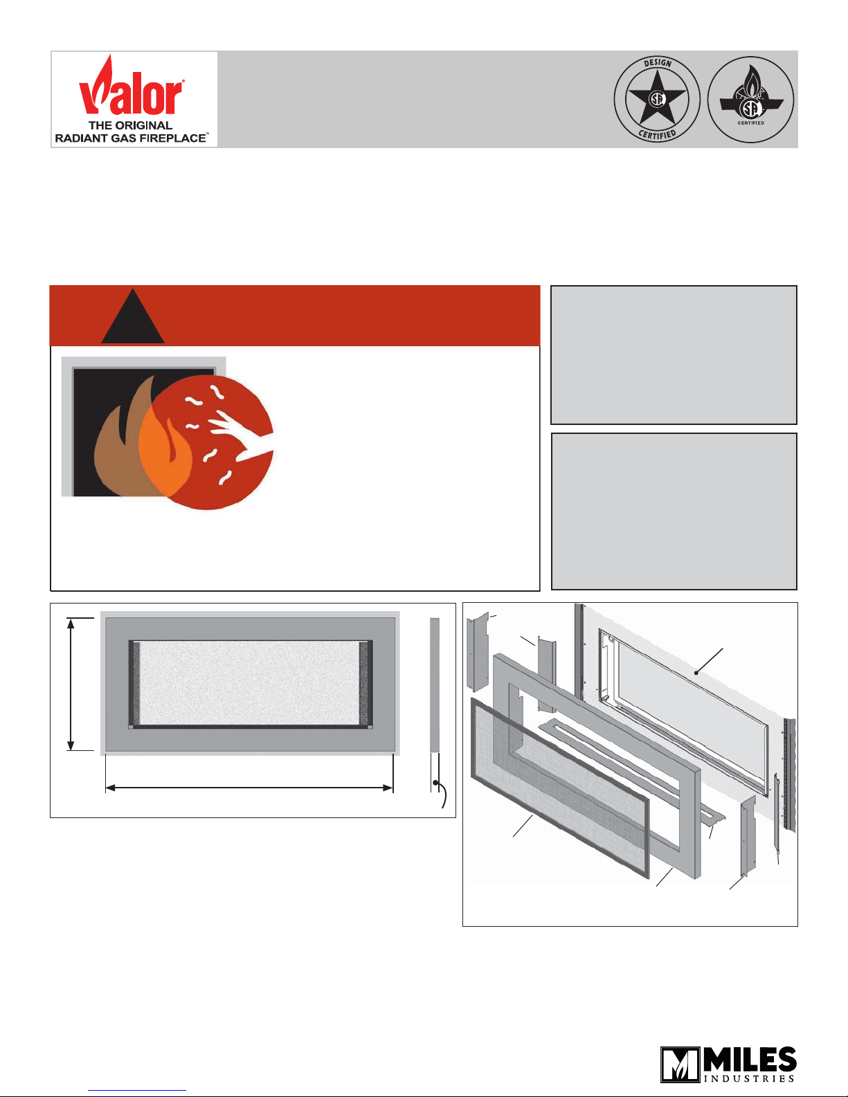
21-1/4” (540 mm)
46-3/16” (1173 mm)
Trim size
The 1550v2 Linear 3-1/2” Surround Kit is designed to be
used on the Linear L1 1500 and Linear L1 2-sided 1600
Valor heaters.
The application of this kit does not affect the venting
capabilities or method of preparation of the heater as
described in the heater installation manual.
This trim fi ts fl at against the cement board with the ability
to tuck additional non-combustible materials up to 1/2
inch thickness behind the trim.
Replacing the side panels on the trim allow noncombustible material thickness to be increased to 1 inch.
Thickness 1-3/8” (35 mm)
LH Trim panel
LH Side door
Barrier screen
Trim
Overview (Fireplace engines sold separately)
Non-combustible
cement board
Plinth
RH Trim panel
RH Side
door
4005356-01
© Copyright Miles Industries Ltd., 2015.
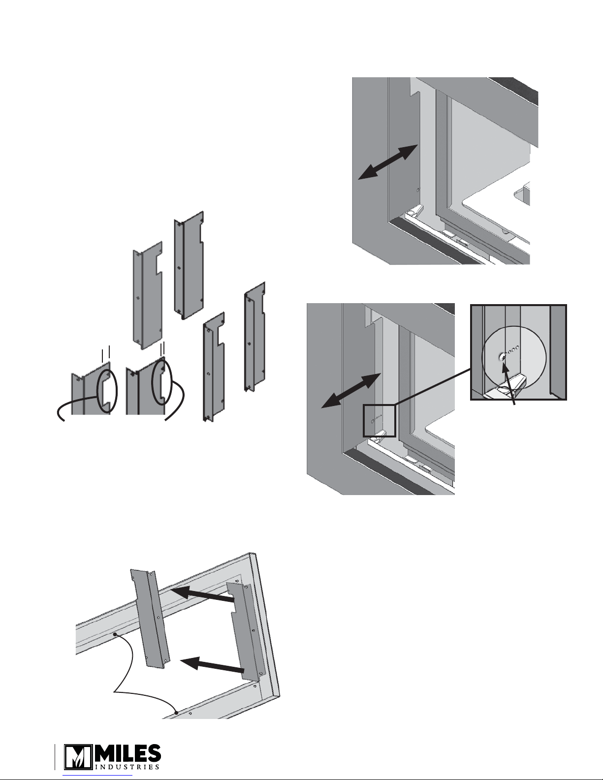
Considerations—fi nish wall thickness
This trim can be adjusted according to the thickness
of the non-combustible wall fi nish. Two options of
installation can be used:
• Wall thickness on top of cement board of 0-1/2”.
For this option, the trim can be installed as it comes
out of the box. Follow installation steps in the next
section Installation.
• Wall thickness on top of cement board of 1/2”-1”.
For this option, the side panels on the trim must be
removed and the extension panels supplied with this
kit must be installed. Proceed to the following steps
before the installation.
LH side
panels
Installation
1. Locate trim inside perimeter of ‘window’ aperture
fl anges, press fi rmly against fi nished face of wall.
2. Select a pre punched hole and secure trim using 4
no 8 screws.
0 - 1/2”,
panels
‘deep’ notch
1/2” - 1”,
panels
‘shallow’ notch
RH side
pannels
Trim Preparation
1. From the rear of the trim, remove the 6 fi xing nuts
(3 per side) retaining the side panels to the trim.
Recycle these panels as they will no longer be
required.
2. Position the extension panels on the rear of the trim
and fi x them with the 6 nuts (3 per side).
Top
Note: The metal
fl ange is wider at
the top of the trim
than at the bottom
Bottom
fi xing
screws
(4)
2
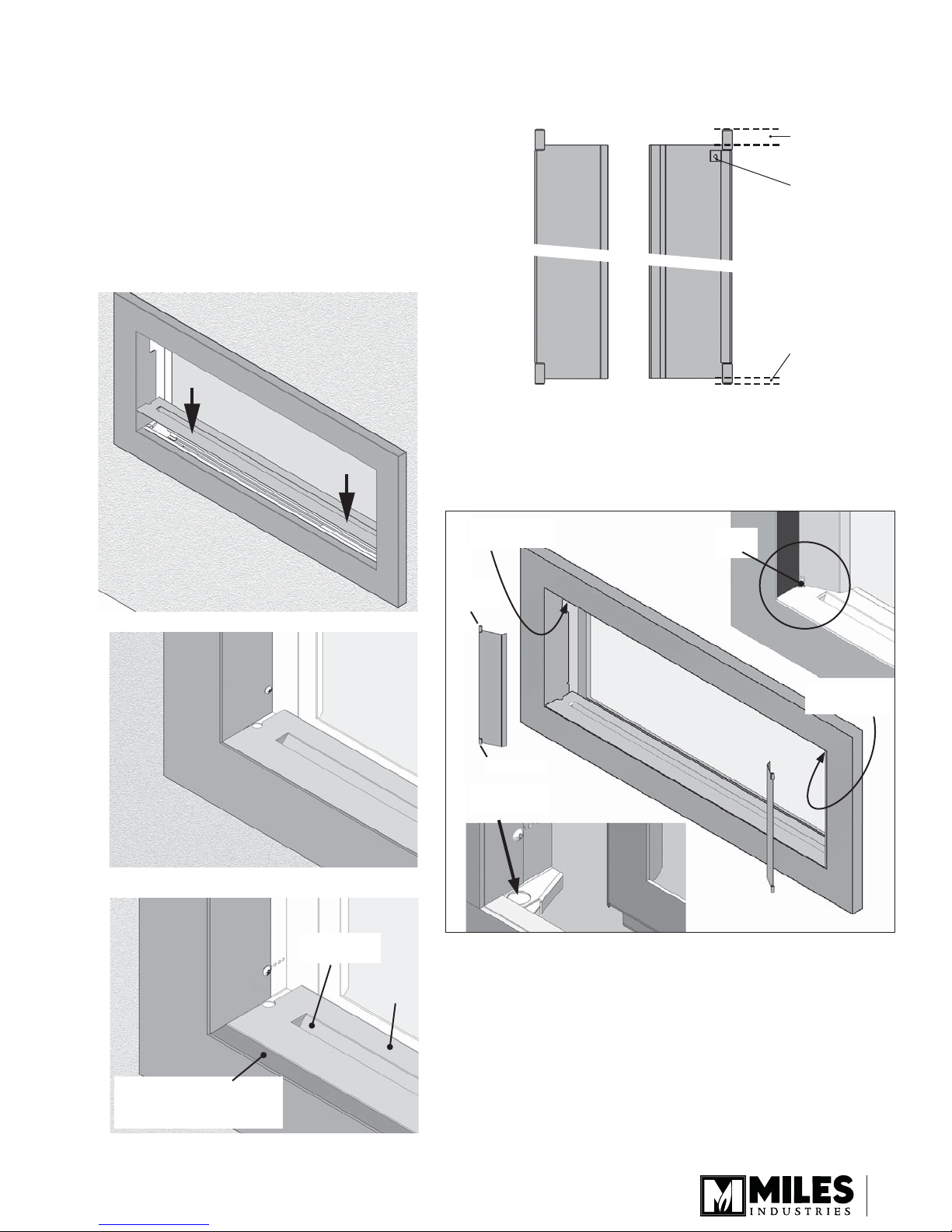
3. Position plinth in space between glass and trim,
TOP of door:
this space is
wider
TOP of door:
tab at the rear
Left door
BOTTOM of door:
this space is
narrower
Rear view
Front view
locate ends onto end support. Ensure plinth is level
with trim.
Notes :
- The opening in the plinth should be oriented as
shown below to allow air to enter while obstructing
any view through the opening.
- Each end of the plinth has a rounded notch
opening to insert the tab of the side doors.
- The bottom edge of the trim is more or less visible
depending of the thickness of the wall fi nish under
the trim.
4. Identify left hand door and its orientation according
to the images below.
5. Locate hinge pin into upper hole.
6. Lower door hinge pin into the notch at the end of
the plinth.
Trim directly on the fi nished cement board
Opening in
the plinth
Insert hinge
pin here
hinge
pin
hinge pin
Insert tab
here
7. Repeat for right hand door.
hinge
pin
Insert hinge
pin here
Flange below plinth is
visible when the trim is on
thicker wall fi nish
Trim on 1” thick wall fi nish
Plinth
3
 Loading...