

Miles Industries H5, 1100LPG, 1100NG, 1150NG, 1150LPG Installation Instructions Manual

H5
Gas Conversion Kit
1100NGK / PGK & 1150NGK / PGK
Use with with Valor Models 1100/1150 Heaters ONLY
Installation Instructions
This appliance is certifi ed for use from 0–4500 feet. For
altitudes above 4500 feet, see local codes.
Kit Contents
1 Pilot injector
1 Main burner elbow injector
1 Set of conversion labels
1 Minimum rate by-pass screw
Tools Required
• Wrenches, to disconnect gas line
• Phillips (+) screwdriver, to remove burner module
• Small (jewelers size) fl at blade screwdriver, to set
pressure
• Small fl at blade screwdriver, to release pressure tap
on valve
• Needle nose pliers, to remove by-pass screw
• Hex (Allen) wrench, 4 mm or 5/32”, to remove pilot
injector
• Manometer, to set pressure when regulator is integral
with valve
WARNING
This conversion kit shall be installed by
a qualifi ed service agency in accordance
with the manufacturer’s instructions and
all applicable codes and requirements of
the authority having jurisdiction. If the
information in these instructions is not
followed exactly, a fi re, explosion or pro-
duction of carbon monoxide may result
causing property damage, personal injury
or loss of life. The qualifi ed service agency
is responsible for the proper installation of
this kit. The installation is not proper and
complete until the operation of the converted appliance is checked as specifi ed in
the manufacturer’s instructions supplied
with the kit.
Use this manual in conjunction with the
installation manual supplied with the
appliance.
Specifi cations
Model
Gas Natural Propane Natural Propane
Altitude (Ft.)* 0-4,500 feet* 0-4,500 feet*
Input Maximum (Btu/h) 28,000 28,000 30,000 30,000
Input Minimum (Btu/h) 13,000 13,000 16,000 16,000
Manifold Pressure (in w.c.) 3.5” 9.0” 4.0” 9.0”
Minimum Supply Pressure (in w.c.) 5.0 11.0 5.0 11.0
Maximum Supply Pressure (in w.c.) 10.0 14.0 10.0 14.0
Main Burner Injector Marking 850 300 850 360
Pilot Injector Marking 51 30 51 30
Min. Rate By-Pass Screw 185 125 195 135
4004585-03
©2014, Miles Industries Ltd.
1100NG 1100LPG 1150NG 1150LPG
General Notes Regarding Conversion
The conversion may be done before or after the
appliance is installed into the cavity. However, the gas
must be connected to set the manifold pressure.
Prepare the appliance
1. If the fi replace is already installed, remove the
access side doors, the front trim, the window, and
fuel bed. Be careful with fuel bed as components
are fragile.
2. Locate shut off valve and isolate.
3. Remove the ceramic liner panels
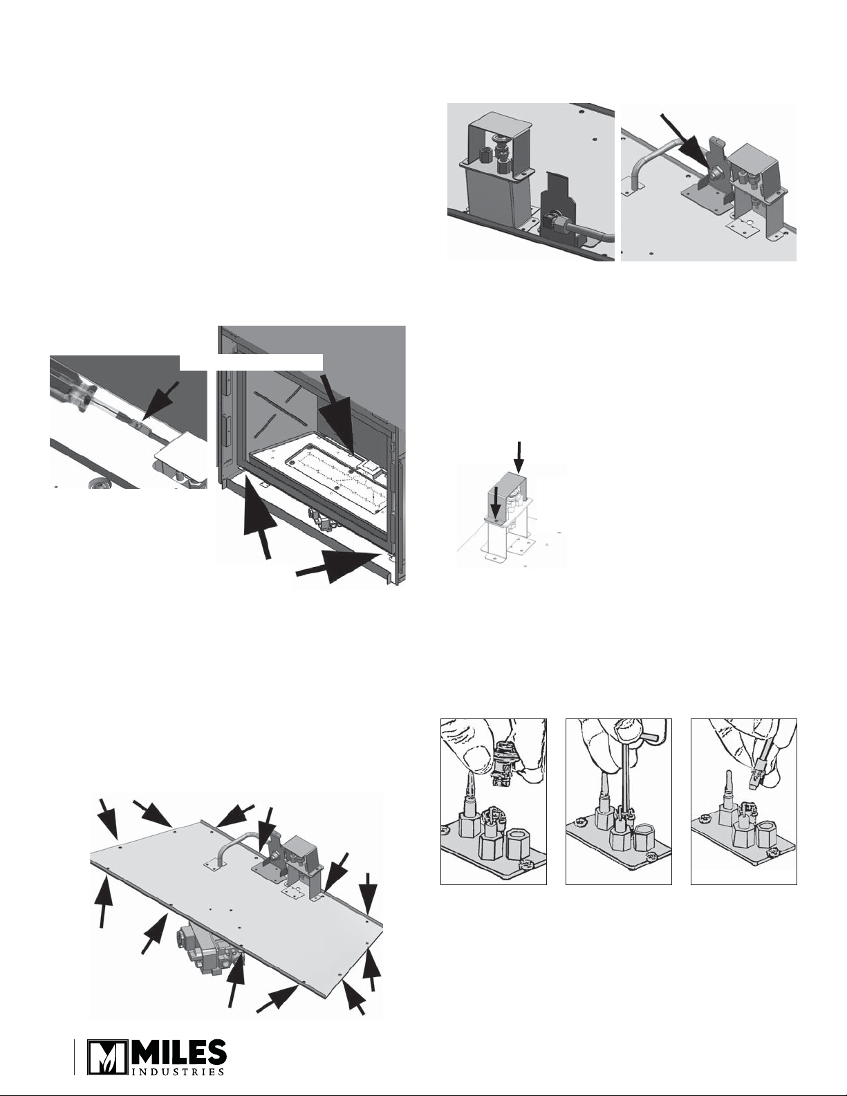
4. Remove the burner platform, unscrew the 2
thumbscrews fi xing the front of the burner to the
fi rebox as indicated, also 1 screw at rear of burner.
Rear fi xing screw
4. Supporting injector elbow, unlock and remove
pipe assembly, remove injector locknut from inside
manifold housing.
Injector elbow pipe
connection
5. Exchange injector elbow from kit, verify the new
injector before you install—see Specifi cations table
on page 1. Reverse the assembly.
6. Reconnect injector elbow to the pipe. tightening pipe
connection.
Convert the pilot injector
1. Remove the pilot hood by pulling on it.
Fixing points underside
of fi rebox
5. Gently pull up the burner rear fi rst and then the
front. Be careful not to hook the pilot hood as
you pull the burner up.
Replace the burner injector
1. Using two wrenches disconnect inlet to valve
control.
2. Remove 12 screws holding module plate to fi rebox
base.
3. Withdraw module from fi rebox.
Remove
pilot cover
(2 screws)
2. Unscrew the pilot injector using an Allen key.
Discard the pilot injector.
3. Replace with the appropriate pilot injector—see
Specifi cations table on page 1. Screw in the new
injector.
4. Refi t the pilot head by pushing down on it. Ensure
that it snaps into position.
2
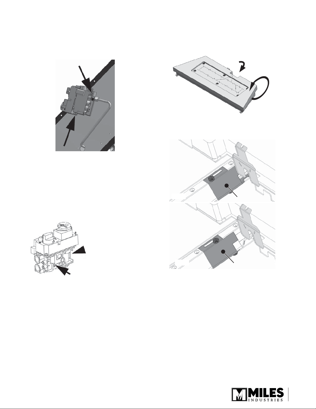
Replace the minimum rate by-pass screw
1. Turn module assembly upside down, unlock and
remove pipe assembly.
2. Remove two screws retaining the valve to
mounting bracket, being careful not to disturb other
connections.
3. Locate and remove the by-pass screw from the
valve and discard. The by-pass screw has a rubber
O-ring and may need to be pulled out using pliers
after unscrewing.
4. Insert the replacement minimum rate by-pass
screw and hand tighten using a screwdriver. Refer
to the Specifi cations table on page 1 for proper
by-pass screw. Note that the number is stamped on
the barrel of the screw.
Adjust the air shutter
The air shutter is located under the ceramic fuel bed at
the back.
1. Carefully turn the fuel bed upside down and locate
the air shutter.
Air shutter
2. Loosen the screws on each side of the shutter and
slide the shutter as indicated below according to the
type of gas used.
NG
Air shutter
Top side of
control valve
Minimum rate
By-pass screw
location
Re-assemble module
1. To reinstall, is a reversal of the procedure.
2. Position and locate module in the fi rebox inserting
the valve fi rst. be careful not to trap cables
between fi rebox fl oor and module
3. Secure module to fi rebox with previously used
screws.
4. Reconnect gas inlet to valve tightening pipe
connection. Open shut off valve and inspect
5. Test for leaks by applying a liquid detergent or soap
solution to inlet connection joint. Bubbles forming
indicate a gas leak.
Never use an open fl ame to check for leaks.
Correct any leak detected immediately.
LPG
3. Re-tighten the screws.
Air shutter
3
 Loading...