

Milesight MS-C3587-PA, MS-C3581-PA, MS-C3586-PA, MS-C3582-PA, MS-C2173-PA User Manual
...
User Manual
F
Network Camera
User Manual
V6.04

Thank you for purchasing our product. If there is any question or request, please do not hesitate
to contact your dealer.
This manual is applicable to the Milesight H.264&H.265 Network Camera, series shown as follows,
except where otherwise indicated.
Milesight H.264 Network Camera
Type
Megapixel
1.3MP
2.0MP
3.0MP
Mini Dome Camera
MS-C2181-PA
MS-C3581-PA
MS-C3586-PA
IR Mini Dome Camera
MS-C2182-PA
MS-C3582-PA
MS-C3587-PA
Vandal-proof Mini Dome
MS-C2173-PA
MS-C3373-PA
MS-C3573-PA
MS-C3377-PA
MS-C3577-PA
Wi-Fi Mini Cube Camera
MS-C2191-PWA
-
MS-C3596-PWA
Mini Bullet Camera
MS-C2163-PNA
MS-C3263-PNA
MS-C3363-PNA
MS-C3367-PNA
MS-C3567-PNA
Remote Focus&Zoom
Mini Bullet Camera
MS-C2163-F(I)PNA
MS-C3263-F(I)PNA
MS-C3363-F(I)PNA
MS-C3367-F(I)PNA
MS-C3567-F(I)PNA
Remote Focus&Zoom
Pro Bullet Camera
MS-C2162-F(I)PNA
MS-C3262-F(I)PNA
MS-C3362-F(I)PNA
MS-C3366-F(I)PNA
MS-C3566-F(I)PNA
Remote Focus&Zoom
Pro Dome Camera
MS-C2172-F(I)PNA
MS-C3272-F(I)PNA
MS-C3372-F(I)PNA
MS-C3376-F(I)PNA
MS-C3576F(I)PNA
Remote Focus&Zoom
Pro Dome(M) Camera
MS-C2172-F(I)PMNA
MS-C3272-F(I)PMNA
MS-C3372-F(I)PMNA
MS-C3376-F(I)PMNA
MS-C3576-F(I)PMNA
Day&Night Pro
Box Camera
MS-C2151-PA
-
MA-C3356-PA
MS-C3556-PA

This Manual explains how to use and manage Milesight network cameras on your network.
Previous experience of networking will be of use when using the products. Please read this manual
carefully before operation and retain it for future reference.
This manual may contain several technically incorrect places or printing errors, and the content is
subject to change without notice. The updates will be added into the new version of this manual.
We will readily improve or update the products or procedures described in the manual.
Copyright Statement
This manual may not be reproduced in any form or by any means to create any derivative such
as translation, transformation, or adaptation without the prior written permission of Milesight
Technology Co., Ltd(Hereinafter referred to as Milesight).
Milesight reserves the right to change this manual and the specifications without prior notice.
The latest specifications and user documentation for all Milesight products are available on our
official website www.milesight.com
Milesight H.265 Network Camera
Type
Megapixel
2.0MP
4.0MP
Vandal-proof Mini Dome
Network Camera
MS-C2973-PB
MS-C4473-PB
Mini Bullet Camera
MS-C2963-PB
MS-C4463-PB
Remote Focus&Zoom
Mini Bullet Camera
MS-C2863-F(I)PB
MS-C2963-F(I)PB
MS-C4463-F(I)PB
Remote Focus&Zoom
Pro Bullet Camera
MS-C2862-F(I)PB
MS-C2962-F(I)PB
MS-C4462-F(I)PB
Remote Focus&Zoom
Pro Dome Camera
MS-C2872-F(I)PB
MS-C2972-F(I)PB
MS-C4472-F(I)PB
Remote Focus&Zoom
Pro Dome(M) Camera
MS-C2872-F(I)PMB
MS-C2972-F(I)PMB
MS-C4472-F(I)PMB

Safety Instruction
These instructions are intended to ensure that user can use the product correctly to avoid danger
or property loss. The precaution measures are divided into “Warnings” and “Cautions”
Warnings: Serious injury or death may be caused if any of these warnings is neglected.
Cautions: Injury or equipment damage may be caused if any of these cautions are neglected.
Warnings: Please follow these safeguards to
prevent injury or death.
Cautions: Please follow these safeguards to
prevent potential injury or material damage.
Warnings
This installation must be conducted by a qualified service person and should strictly
comply with the electrical safety regulations of the local region
To avoid risk of fire and electric shock, do keep the product away from rain and moisture
Do not touch components such as heat sinks, power regulators, and processors, which
may be hot
Source with DC 12V or PoE
Please make sure the plug is firmly inserted into the power socket
When the product is installed on a wall or ceiling, the device should be firmly fixed
If the product does not work properly, please contact your dealer. Never attempt to
disassemble the camera by yourself
Cautions
Make sure that the power supply voltage is correct before using the camera
Do not store or install the device in extremely hot or cold temperatures, dusty or damp
locations, and do not expose it to high electromagnetic radiation
Only use components and parts recommended by manufacturer
Do not drop the camera or subject it to physical shock
To prevent heat accumulation, do not block air circulation around the camera
Laser beams may damage image sensors. The surface of image sensors should not be
exposed to where a laser beam equipment is used
Use a blower to remove dust from the lens cover
Use a soft, dry cloth to clean the surface of the camera. Stubborn stains can be removed
using a soft cloth dampened with a small quantity of detergent solution, then wipe dry
Do not use volatile solvents such as alcohol, benzene or thinners as they may damage the
surface finishes
Save the package to ensure availability of shipping containers for future transportation

Environmental Protection
Please recycle this device in a responsible manner. Refer to local environmental regulations for
proper recycling. Do not dispose of devices in unsorted municipal waste.

Table of Contents
Chapter I Product Description
..............................................................................................................
1
1.1 Product Overview
....................................................................................................................
1
1.2 Key Features
............................................................................................................................
1
1.3 Hardware Overview
.................................................................................................................
2
1.4 Hardware Installation
............................................................................................................
12
1.5 How to Connect to Alarm Interface
.......................................................................................
28
1.6 System Requirements
............................................................................................................
28
Chapter II Network Connection
..........................................................................................................
29
2.1 Setting the Camera over the LAN
..........................................................................................
29
2.1.1 Connect the Camera to the PC Directly
.......................................................................
29
2.1.2 Connect via a Switch or a Router
.................................................................................
29
2.2 Setting the camera over the WAN
.........................................................................................
29
2.2.1 Static IP Connection
.....................................................................................................
30
2.2.2 Dynamic IP Connection
................................................................................................
30
Chapter III Accessing the Network Camera
........................................................................................
32
3.1 Assigning An IP Address
.........................................................................................................
32
3.1.1 Assigning An IP Address Using IPCTools
......................................................................
32
3.1.2 Assign An IP Address via Browser
................................................................................
36
3.2 Accessing from the Web Browser
..........................................................................................
39
3.2.1 Access over IE Browser
................................................................................................
39
3.3 Accessing from Milesight VMS (Video Management Software)
...........................................
41
Chapter IV System Operation Guide
...................................................................................................
43
4.1 Live Video
..............................................................................................................................
43
4.2 Playback
.................................................................................................................................
45
4.3 Basic Settings
.........................................................................................................................
47
4.3.1 Video
............................................................................................................................
47
4.3.2 Image
...........................................................................................................................
49
4.3.3 Audio
............................................................................................................................
52
4.3.4 Wi-Fi
.............................................................................................................................
54
4.3.5 Network
.......................................................................................................................
56
4.3.6 Date &Time
..................................................................................................................
58
4.4 Advanced Settings
.................................................................................................................
60
4.4.1 Image
...........................................................................................................................
60
4.4.2 Network
.......................................................................................................................
62
4.4.3 Alarm
...........................................................................................................................
67
4.4.4 Storage
.........................................................................................................................
73
4.4.5 Security
........................................................................................................................
78
4.4.6 SIP
................................................................................................................................
80
4.4.7 Logs
..............................................................................................................................
83
4.5 System
....................................................................................................................................
84
4.6 Maintenance
..........................................................................................................................
84
Chapter V Services
..............................................................................................................................
86

1
Chapter I Product Description
1.1 Product Overview
Milesight provides a consistent range of cost-effective and reliable network cameras to fully
meet your requirements. Based on embedded Linux operating system, Milesight network
cameras could be easily accessed and managed either locally or remotely with great reliability.
Built-in high-performance DSP video processing modules, the cameras pride on low power
consumption and high stability. They support state-of-the-art H.265/H.264/MJPEG video
compression algorithm and industry-leading HD dual-stream technology to achieve the highest
level of video image quality under the limited network resources. It is fully functional, supporting
for flexible and comprehensive alarm linkage mechanism, day and night auto switch, smart PTZ
control and privacy masking, etc.
In practical applications, Milesight network cameras could either work independently in the LAN,
or be networked to form a powerful safety monitoring system. It is widely used in fields such as
finance, education, industrial production, civil defense, health care for security’s sake.
1.2 Key Features
Based on Linux OS with high reliability
H.265/H.264/MJPEG video compression capability
Support ONVIF Profile S
Support three streams
Support PoE
ICR filter with auto switch, true day/ night
Built-in WEB server, support IE/ Firefox/ Chrome/ Safari browser
UPnP protocol for the easy management of IPC
Motion Detection, Privacy Masking, Network Fault Detection and ROI
FTP upload, SMTP upload, SD card record and SIP phone
G.711/AAC audio compression capability
Alarm I/O(built-in for bullet and box cameras, optional for dome cameras)
Built-in Microphone(built-in for (IR) Mini Dome and Vandal-proof Mini Dome, optional for
Pro Dome)
Real-time video electronic amplification
Three-privilege levels of users for flexible management
Micro SD/SDHC/SDXC card local storage support, expand the edge storage
Local PAL/NTSC signal output
2
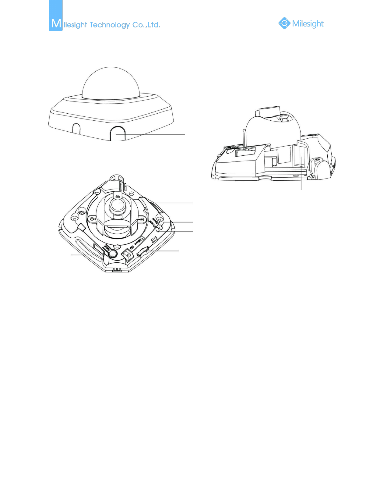
1.3 Hardware Overview
1. Mini Dome Network Camera
Press Button
Ethernet Port (PoE)
Lens
Error LED Indicator
Power LED Indicator
Micro SD/SDHC/SDXC Card Slot
Reset
Figure 1-3-1 Mini Dome
Note:
1) Error LED Indicator: Error LED Indicator is on when the device starts up or runs error.
2) Reset Button: Press “Reset” button for 5 seconds, the device will be restored to factory
default.
3) Only PoE is available for power supply.
3
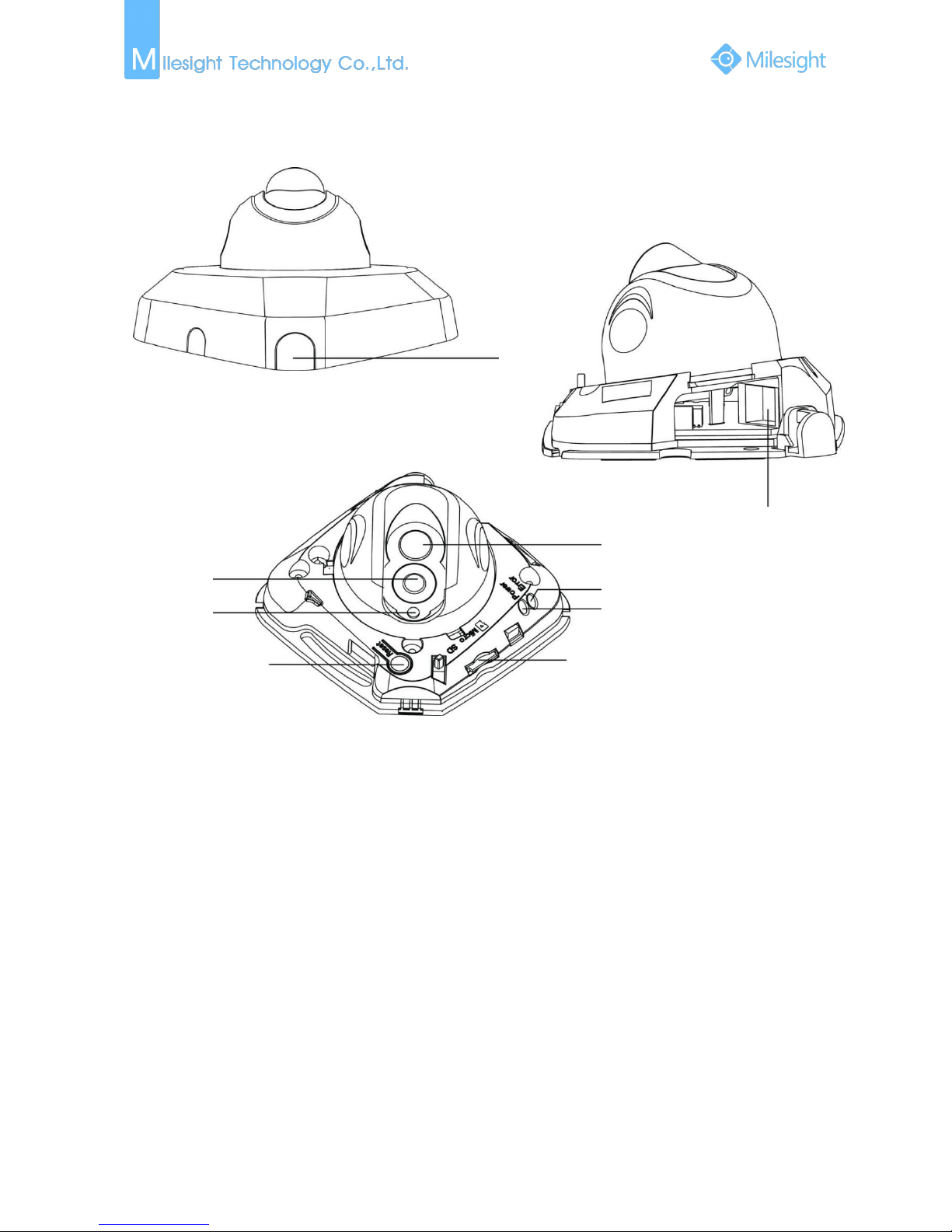
2. IR Mini Dome Network Camera
Ethernet Port (PoE)
Lens
Press Button
Error LED Indicator
Power LED Indicator
Micro SD/SDHC/SDXC Card Slot
Reset
IR LEDs
Light Sensor
Figure 1-3-2 IR Mini Dome
Note:
1) Error LED Indicator: Error LED Indicator is on when the device starts up or runs error.
2) Reset Button: Press “Reset” button for 5 seconds, the device will be restored to factory
default.
3) Only PoE is available for power supply.
4
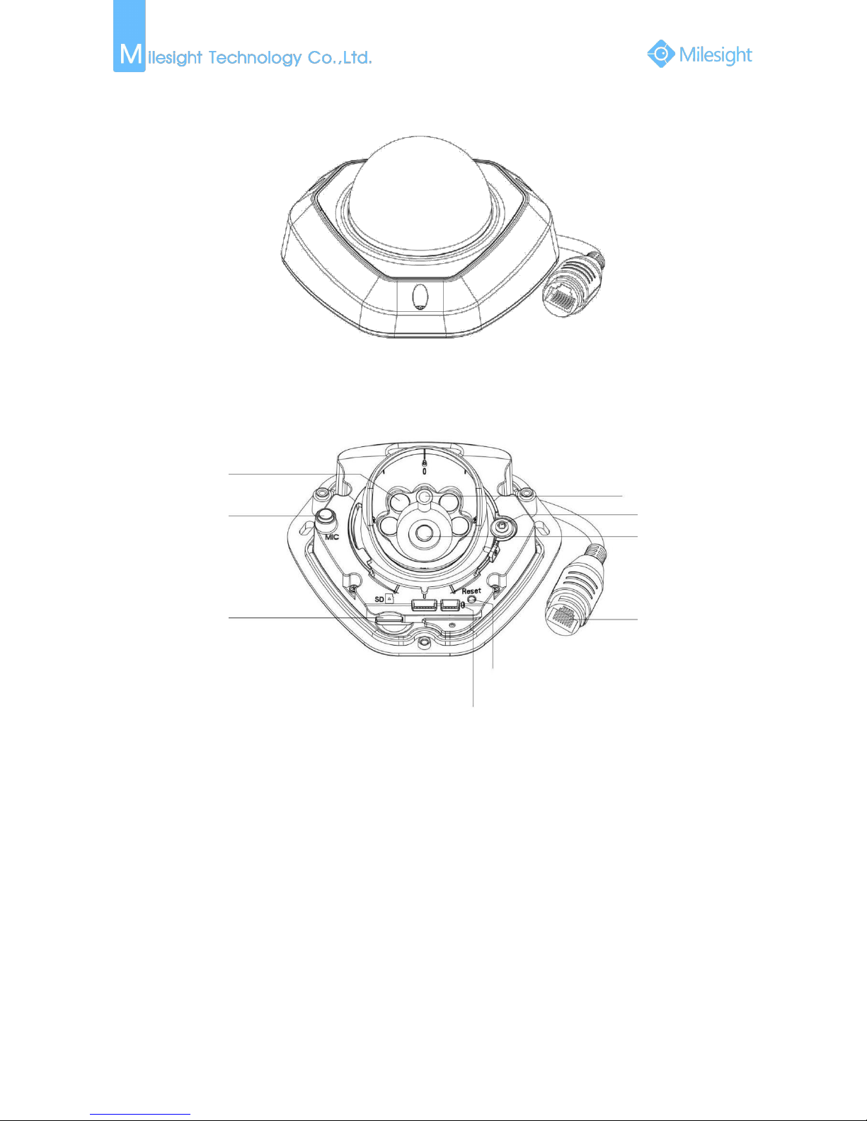
3. Vandal-proof Mini Dome
Figure 1-3-3
Figure 1-3-4 Vandal-proof Mini Dome
Note:
1) Error LED Indicator: Error LED Indicator is on when the device starts up or runs error.
2) Reset Button: Press “Reset” button for 5 seconds, the device will be restored to factory
default.
3) Only PoE is available for power supply.
IR LEDs
Microphone
Micro SD/SDHC/SDXC
Card Slot
Power and System LED Indicator
Reset
Ethernet Port
(PoE)
Lens
Screw
Light Sensor
5
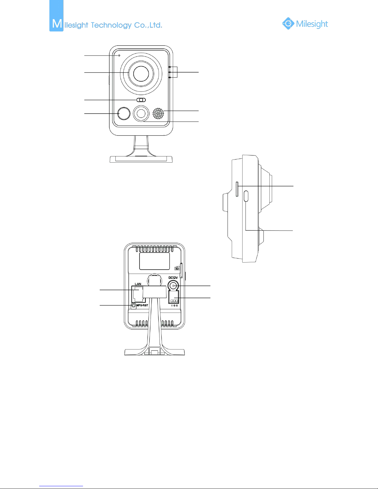
4. Mini Cube Network Camera
Figure 1-3-5 Wi-Fi Mini Cube Camera
Note:
1) SIP Button: Trigger alarm via SIP calling. After this button is pressed, the camera will call the SIP
Phone.
2) WPS Button: Press this button, and then press the WPS button on your router to set up
wireless connection automatically.
3) DC 12V and PoE are available for power supply;
Microphone
Lens
Light Sensor
IR LEDs
LED Indicators
Speaker
PIR Sensor or SIP Button
Micro SD/SDHC/SDXC
Card Slot
SIP Button
Ethernet Port(PoE)
WPS/Reset Button
Power Connector
Alarm Input/Output
6
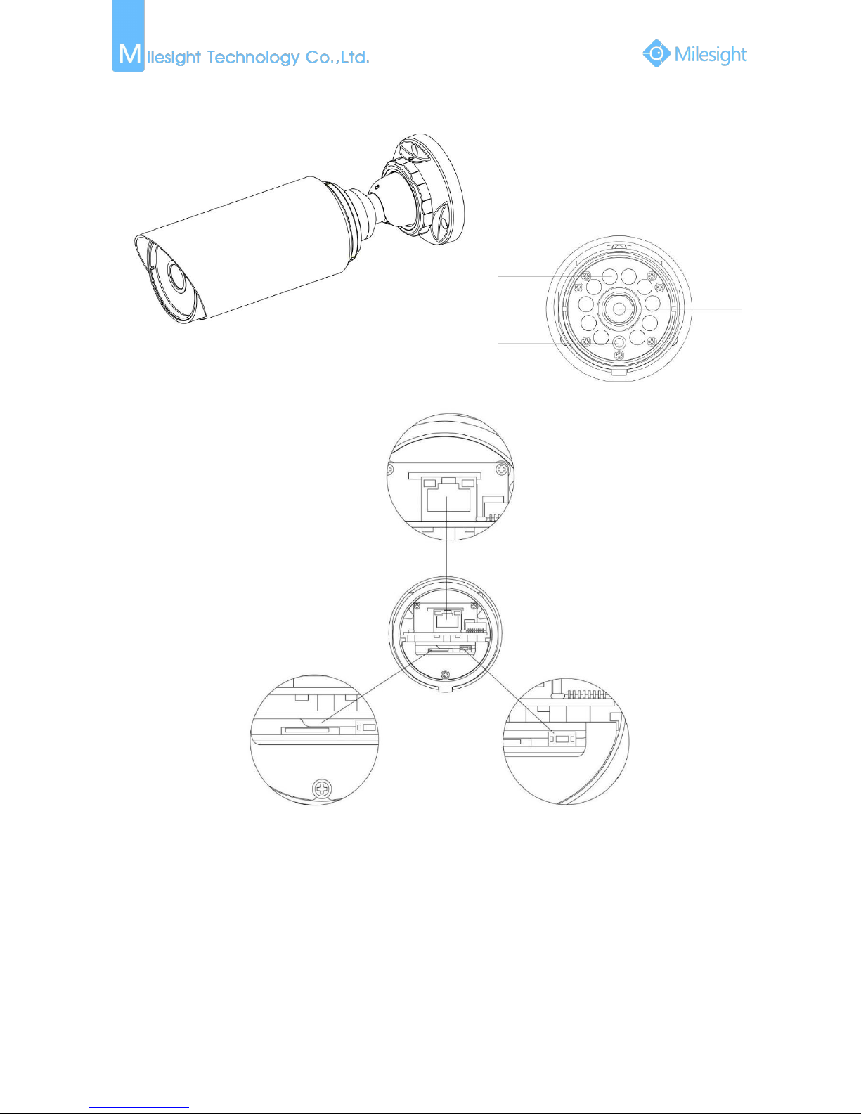
5. Mini Bullet Network Camera
Figure 1-3-6 Mini Bullet Camera
Note:
1) Only PoE is available for power supply.
IR LEDs
Light Sensor
Lens
Ethernet Port(PoE)
Micro SD/SDHC/SDXC Card Slot
Reset Button
7
6. Remote Focus&Zoom Mini Bullet Camera
Figure 1-3-7 Remote Focus&Zoom Mini Bullet Camera
Note:
1) DC 12V and PoE are available for power supply.
IR LEDs
Light Sensor
Lens
DC 12V
Ethernet Port(PoE)
Micro SD/SDHC/SDXC Card Slot
Reset Button
8
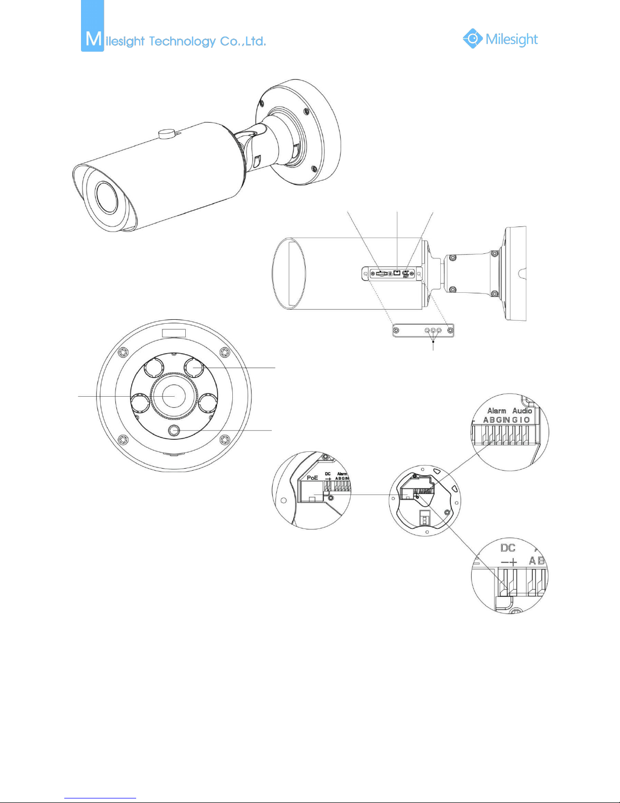
7.
Pro Bullet Camera
Figure 1-3-8 Pro Bullet Camera
Note:
1) DC 12V and PoE are available for power supply.
Ethernet Port (PoE)
Alarm /Audio
Power Connector
Lens
Light Sensor
IR LEDs
Micro SD/SDHC/SDXC
Card Slot
BNC
Reset
Breather
9
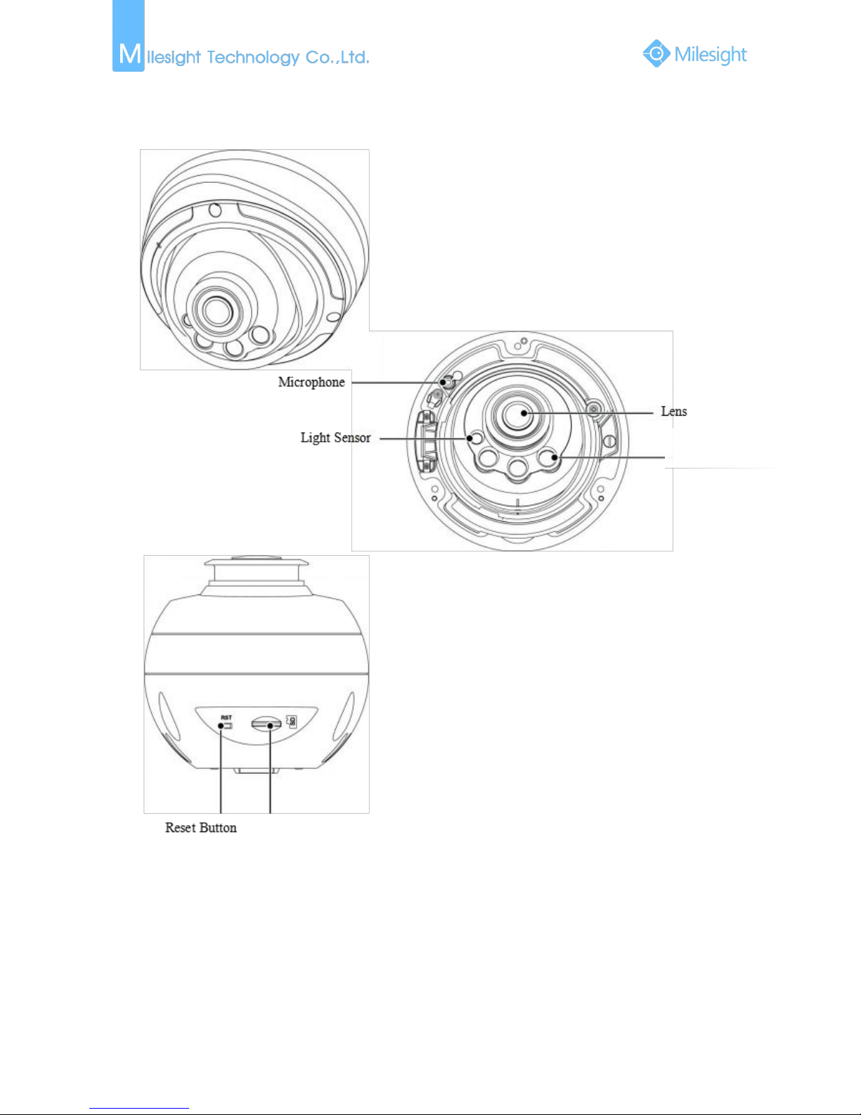
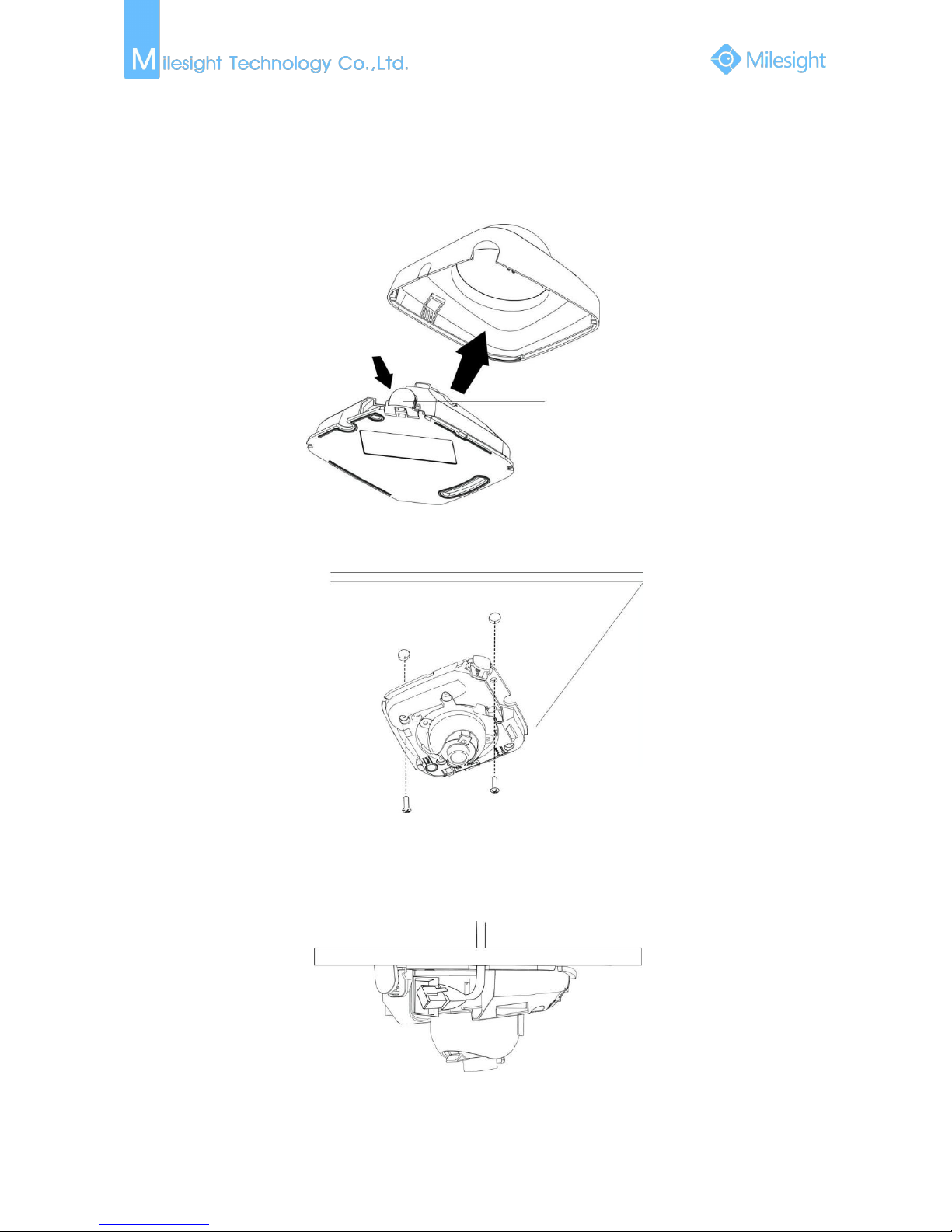
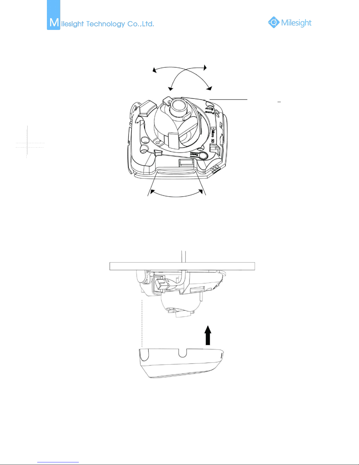
8. Pro Dome Network Camera
Note:
1) There are two versions for Pro Dome: Standard and Multiple Interface, the interface’s pictures
are as following;
2) Multiple Interface adopts the external interface “Audio In” instead of the Microphone built-in;
IR Lens
Micro SD/SDHC/SDXC Card Slot
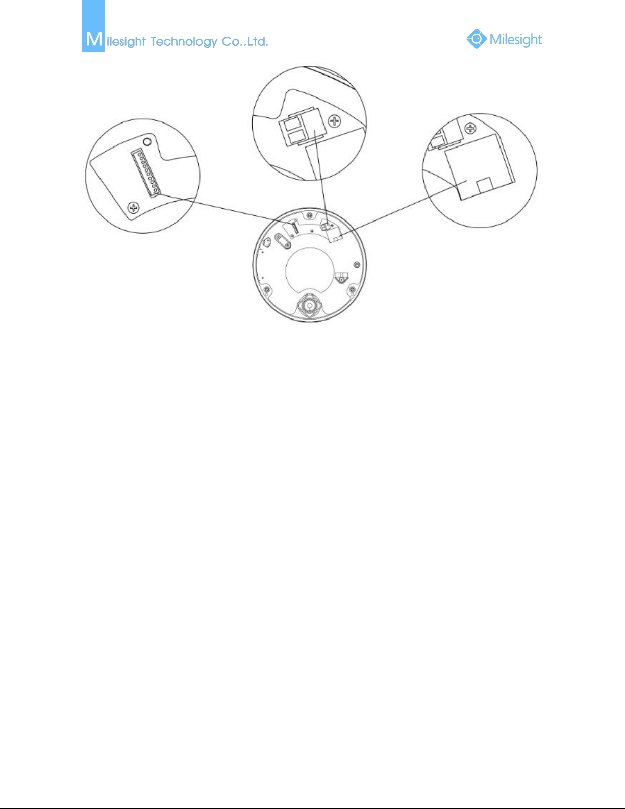
10
Figure 1-3-9 Pro Dome Camera(Standard Interface)
DC 12V
Ethernet Port(PoE)
WAFER Contact
11
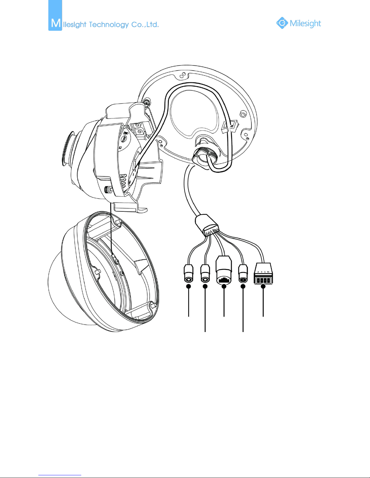
Figure 1-3-10 Pro Dome Camera(Multiple Interface)
Audio In
Audio Out
Ethernet Port
(PoE)
DC 12V
External Interface
12
1.4 Hardware Installation
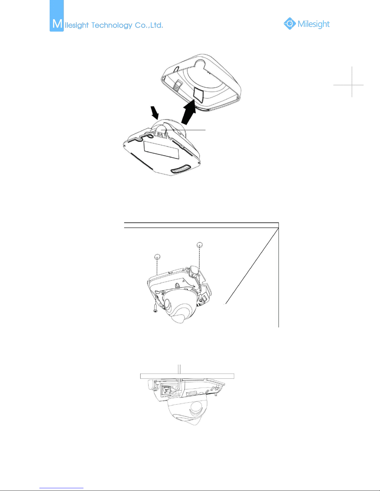
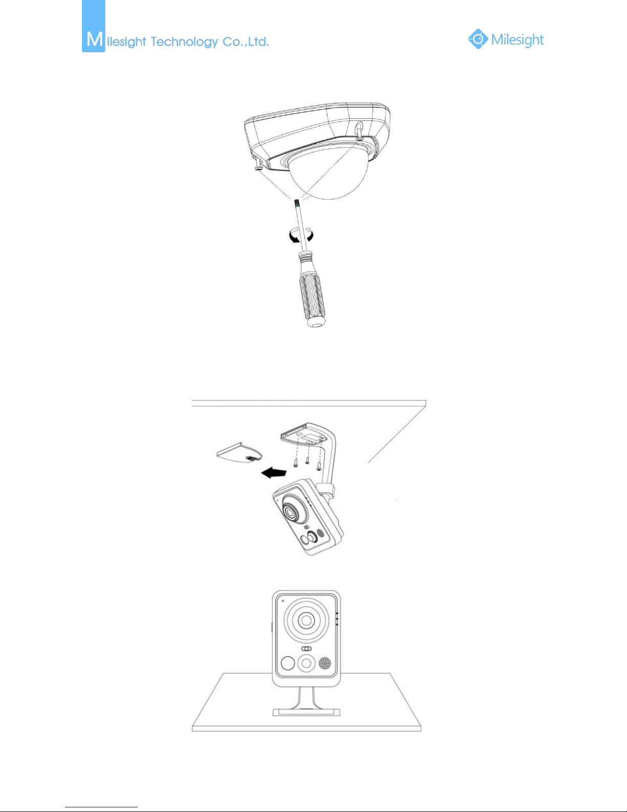
1. Mini Dome Network Camera
Step1: Remove the dome cover;
Press Button
Step2: Secure the screws;
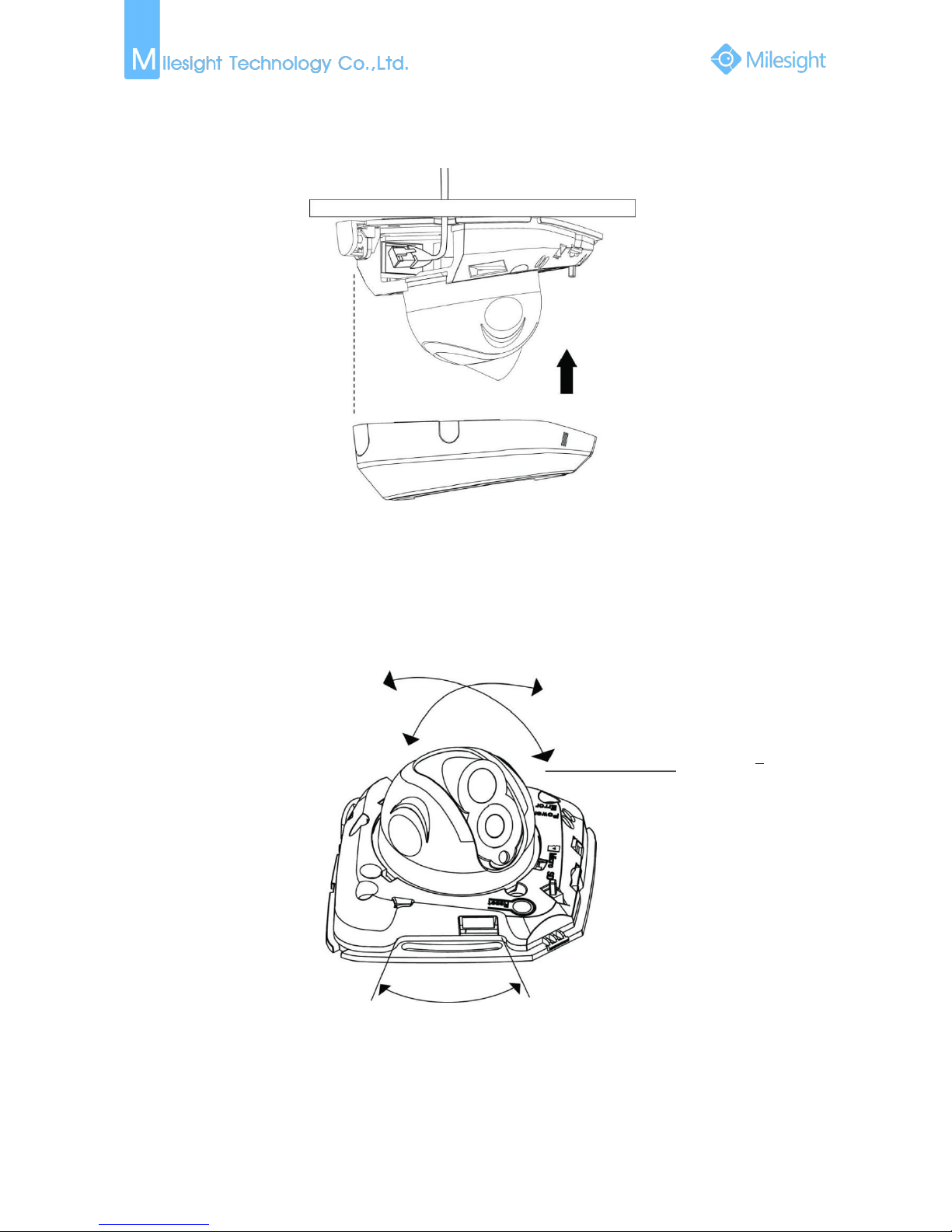
Step3: Connect and route an Ethernet cable through the ceiling or wall;
13
Step4: Adjust the lens angle and focus;
Pan Range:+15°
Tilt Range:0-90°
20°
Step5: Attach the dome cover;
2. IR Mini Dome Network Camera
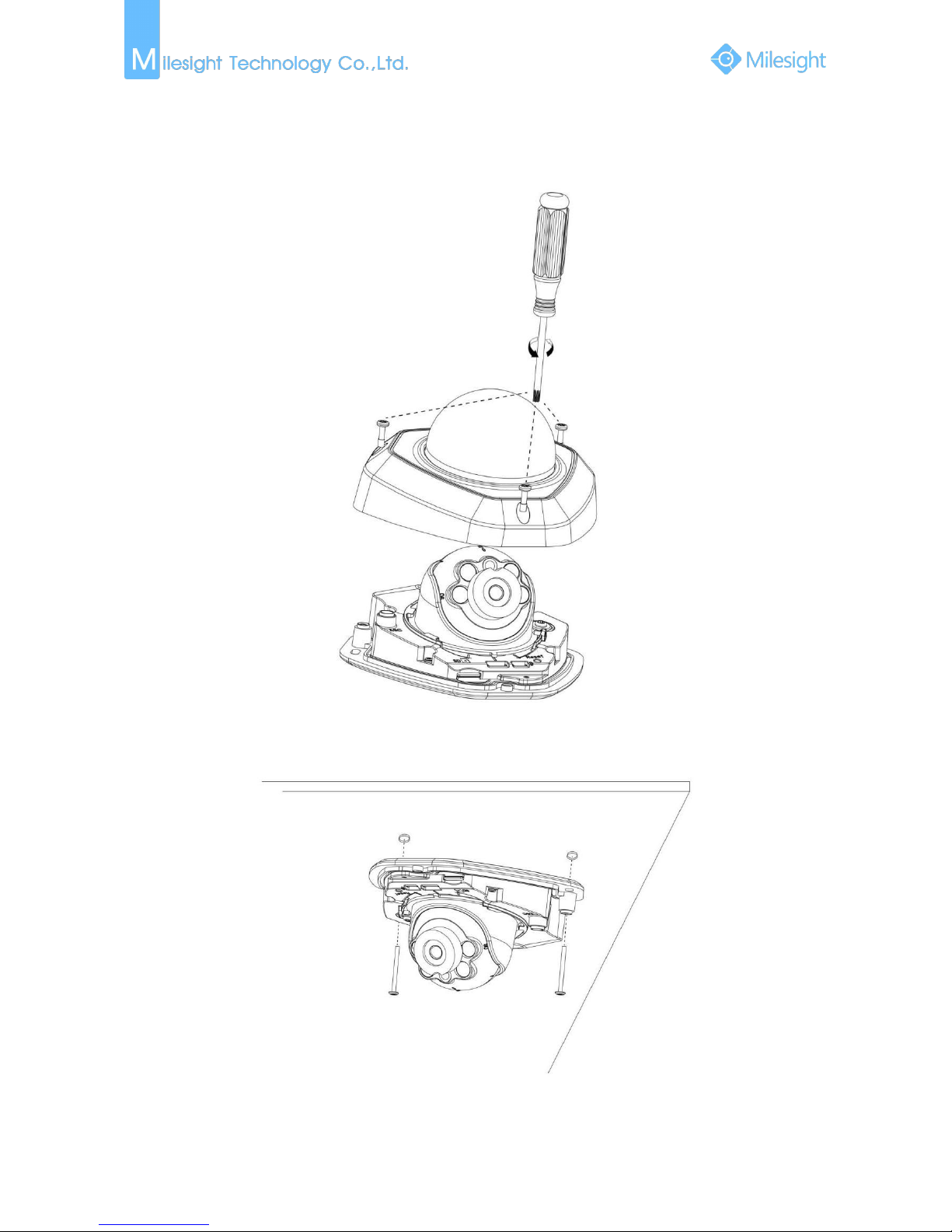
Step1: Remove the dome cover;
14
Press Button
Step2: Secure the screws;
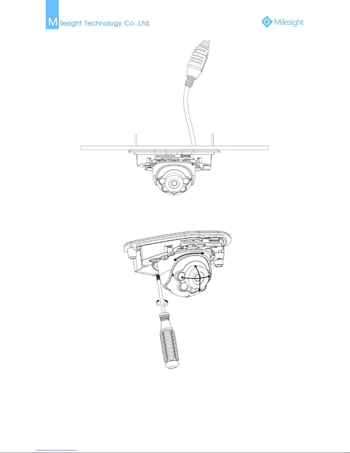
Step3: Connect and route an Ethernet cable through the ceiling or wall;
15
Step4: Attach the dome cover;
Step5: Adjust the lens angle and focus;
Pan Range:+17.5°
Tilt Range:20-60°
20°
16
3. Vandal-proof Mini Dome
Step1: Remove the dome cover;
Step2: Secure the screws;
17
Step3: Connect and route an Ethernet cable through the ceiling or wall;
Step4: Loosen the screw and adjust the lens angle and focus;
18
Step5: Attach the dome cover;
4. Mini Cube Network Camera
Step1: Mount the cube camera to the ceiling or wall, or place the cube camera horizontally;
19
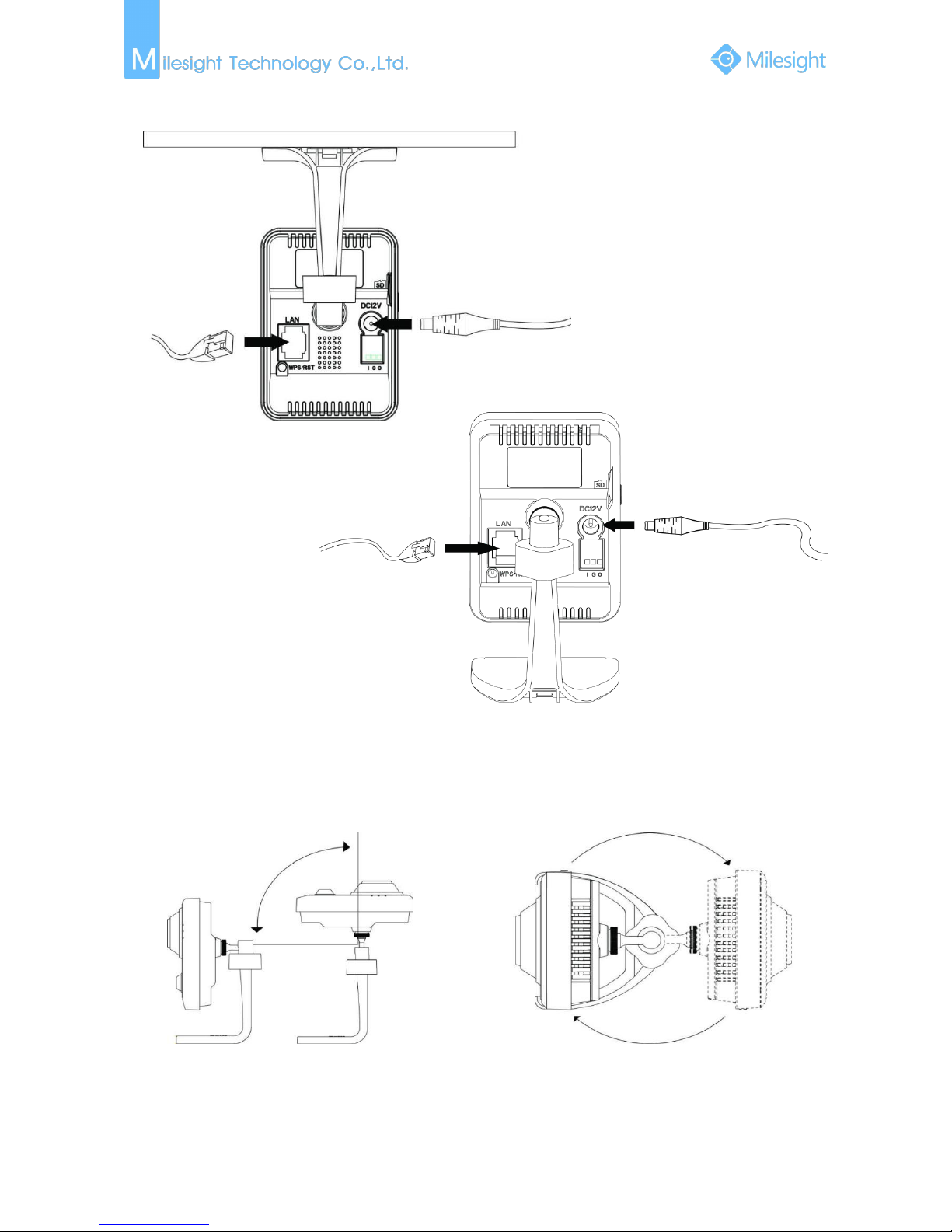
Step2: Connect the power adapter and Ethernet cable;
Power Cable
Ethernet Cable
Step3: Adjust the shooting direction;
90°
360°
20
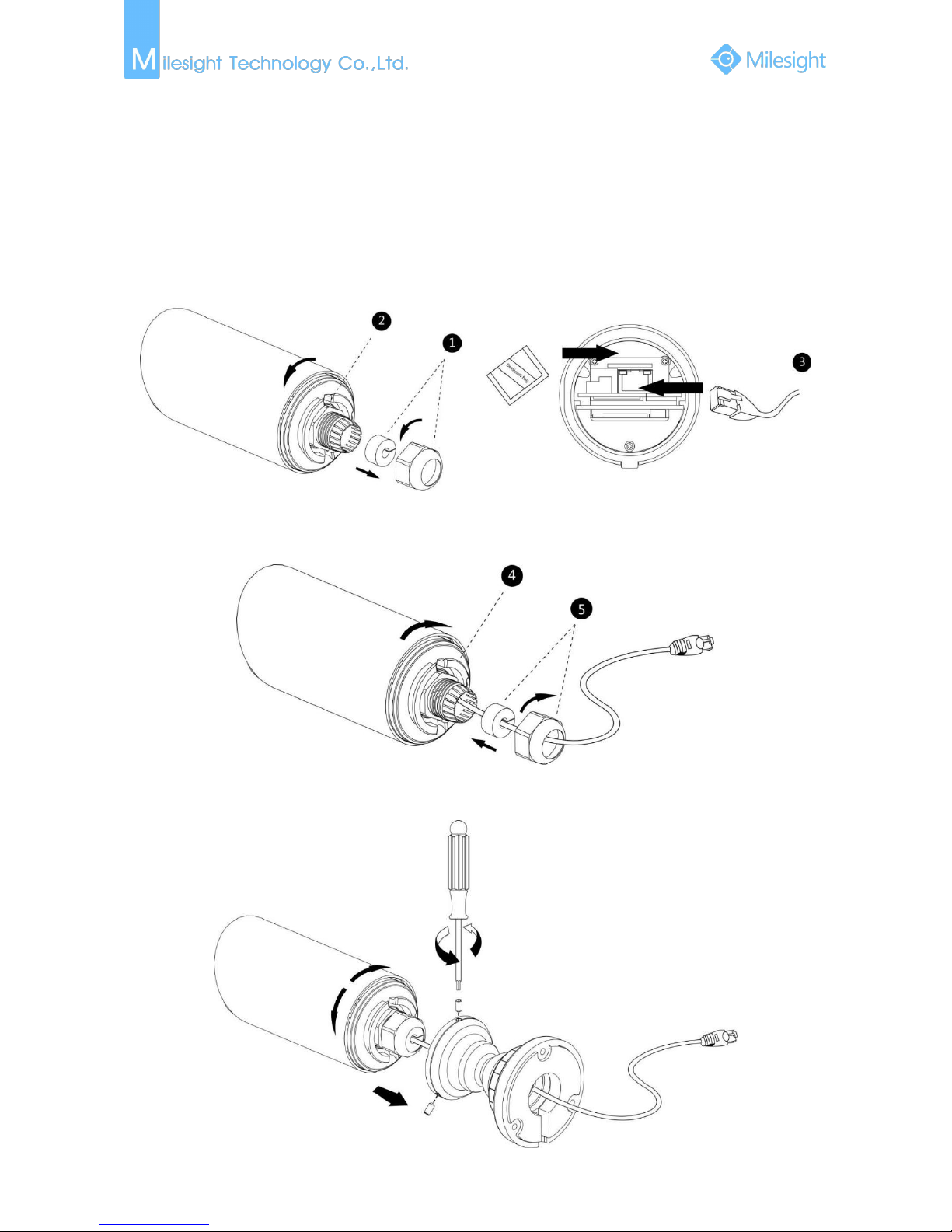
5. Mini Bullet Network Camera
Step1: Loosen the waterproof connector, and then remove the rubber seal, and the waterproof
connector;
Step2: Loosen and open the rear cover;
Step3: Install a Micro SD/SDHC card, connect an Ethernet cable and pass it through the rubber seal,
attach the supplied desiccant bag to the inner side of the network camera (Please replace
the desiccant bag with a new one once you open the rear cover);
Step4: Install and tighten the rear cover;
Step5: Tighten the rubber seal, seal clamp, and cap nut of the waterproof connector;
Step6: Pass the Ethernet cable through the center of the mount bracket, put the bracket and
camera together, rotate the bracket and fasten the bracket using screws;
21
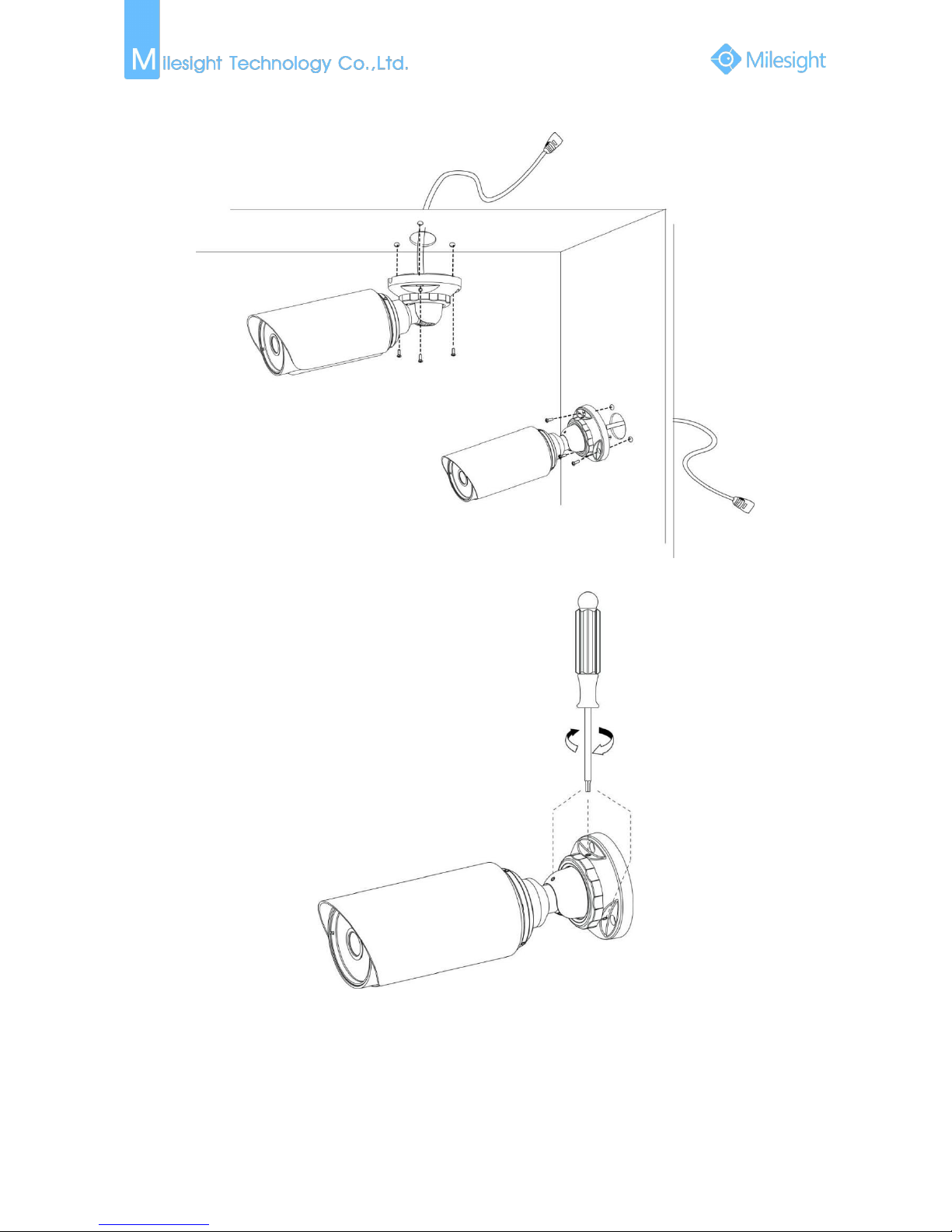
Step7: Mount the camera to the ceiling or wall;
Step8: Adjust the shooting direction;
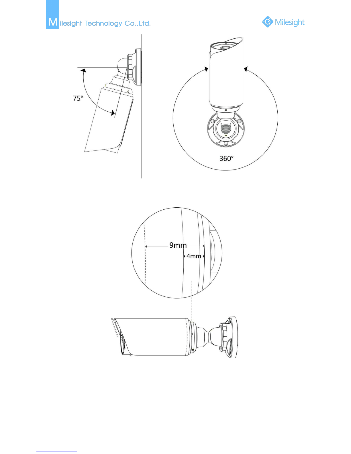
22
Note:
The upper cover of the mini bullet camera could only be moved forward for 5mm at most to
ensure better field of view.
 Loading...