

Milesight MS-C2975-PB, MS-C5381-PB, MS-C5375-PB, MS-C5383-PB, MS-C2975-EPB User Manual
...
Network Camera
User Manual
V7.14

Thank you for purchasing our product. If there is any questions or requests, please do not hesitate
Milesight H.265 Network Camera
Type
Megapixel
2MP
2MP
5MP
4K
Mini Dome Network Camera
—
MS-C2981-PB
MS-C5381-PB
—
IR Mini Dome Network Camera
—
MS-C2983-PB
MS-C5383-PB
—
Vandal-proof Mini Dome Network Camera
—
MS-C2973-PB
MS-C5373-PB
—
Weather-proof Mini Dome NetworkCamera
—
MS-C2975-PB
MS-C5375-PB
—
AF Motorized Mini Dome Network Camera
—
MS-C2975-EPB
MS-C5375-EPB
—
Mini Bullet Network Camera
—
MS-C2963-(R)PB
MS-C5363-PB
MS-C8163-PB
Vandal-proof Mini Bullet NetworkCamera
—
MS-C2964-PB
MS-C5364-PB
—
Motorized Mini Bullet Network Camera
—
MS-C2963-(R)F(I)PB
MS-C5363-F(I)PB
—
Vandal-proof MotorizedMini Bullet Network
Camera
MS-C2864-(R)F(I)PB
MS-C2964-(Q)(T)(R)F(I)PB/
MS-C2964-(Q)(R)F(I)LPB
MS-C5364-(H)F(I)PB
MS-C8164-(H)F(I)PB
180°Panoramic Mini Bullet Network Camera
——MS-C5365-PB
MS-C8165-PB
Motorized Pro Bullet Network Camera
MS-C2862-(R)F(I)PB
MS-C2962-(Q)(T)(R)F(I)PB/
MS-C2962-RF(I)APB/
MS-C2962-(Q)(R)F(I)LPB
MS-C5362-(H)F(I)PB
MS-C8162-(H)F(I)PB/
MS-C8262-F(I)PB
Motorized Pro Dome Network Camera
MS-C2872-(R)F(I)PB
MS-C2972-(Q)(T)(R)F(I)PB/
MS-C2972-RF(I)APB
MS-C5372-(H)F(I)PB
MS-C8172-(H)F(I)PB
12x AF Motorized
Pro Bullet Network Camera
—
MS-C2962-(Q)(T)(R)EPB/
MS-C2962-REAPB/
MS-C2962-(Q)(R)ELPB
MS-C5362-(H)EPB
—
(ABF) Pro Box Network Camera
MS-C2851-(R(E))PB
MS-C2951-(Q)(T)(R)(E)PB/
MS-C2951-R(E)APB/
MS-C2951-(Q)(R)(E)LPB
MS-C5351-(H)PB
MS-C8151-(H)PB
to contact your dealer.
This manual is applicable to the Milesight H.265 Network Camera, series shown as follows, except
where otherwise indicated.
This Manual explains how to use and manage Milesight network cameras on your network.
Warnings: Please follow these safeguards to
prevent injury or death.
Cautions: Please follow these safeguards to
prevent potential injury or material damage.
Previous experience of networking will be of use when using the products. Please read this manual
carefully before operation and retain it for future reference.
This manual may contain several technically incorrect places or printing errors, and the content is
subject to change without notice. The updates will be added into the new version of this manual.
We will readily improve or update the products or procedures described in the manual.
Copyright Statement
This manual may not be reproduced in any form or by any means to create any derivative such as
translation, transformation, or adaptation without the prior written permission of Milesight
Technology Co., Ltd(Hereinafter referred to as Milesight).
Milesight reserves the right to change this manual and the specifications without prior notice. The
latest specifications and user documentation for all Milesight products are available on our official
website www.milesight.com
Industry Canada ICES-003 Compliance:
This Class B digital apparatus complies with Canadian ICES-003.
Cet appareil numerique de la classe B est conforme a la norme NMB-003 du Canada.
Safety Instruction
These instructions are intended to ensure that user can use the product correctly to avoid danger
or property loss. The precaution measures are divided into “Warnings” and “Cautions”
Warnings: Serious injury or death may be caused if any of these warnings is neglected.
Cautions: Injury or equipment damage may be caused if any of these cautions are neglected.
Warnings
This installation must be conducted by a qualified service person and should strictly
comply with the electrical safety regulations of the local region
To avoid risk of fire and electric shock, do keep the product away from rain and moisture
before installed.
Do not touch components such as heat sinks, power regulators, and processors, which
may be hot
2012/19/EU (WEEE directive): Products marked with this symbol cannot be disposed
of as unsorted municipal waste in the European Union. For proper recycling, return
this product to your local supplier upon the purchase of equivalent new equipment,
or dispose of it at designated collection points. For more information
see:www.recyclethis.info.
2006/66/EC (battery directive): This product contains a battery that cannot be
disposed of as unsorted municipal waste in the European Union. See the product
documentation for specific battery information. The battery is marked with this
symbol, which may include lettering to indicate cadmium (Cd), lead (Pb), or
Source with DC 12V or PoE
Please make sure the plug is firmly inserted into the power socket
When the product is installed on a wall or ceiling, the device should be firmly fixed
If the product does not work properly, please contact your dealer. Never attempt to
disassemble the camera by yourself
Cautions
Make sure that the power supply voltage is correct before using the camera
Do not store or install the device in extremely hot or cold temperatures, dusty or damp
locations, and do not expose it to high electromagnetic radiation
Only use components and parts recommended by manufacturer
Do not drop the camera or subject it to physical shock
To prevent heat accumulation, do not block air circulation around the camera
Laser beams may damage image sensors. The surface of image sensors should not be
exposed to where a laser beam equipment is used
Use a blower to remove dust from the lens cover
Use a soft, dry cloth to clean the surface of the camera. Stubborn stains can be removed
using a soft cloth dampened with a small quantity of detergent solution, then wipe dry
Do not use volatile solvents such as alcohol, benzene or thinners as they may damage the
surface finishes
Save the package to ensure availability of shipping containers for future transportation
EU Conformity Statement
mercury(Hg). For proper recycling, return the battery to your supplier or to a designated
collection point. For more information see:www.recyclethis.info.

Table of Contents
Chapter I Product Description.............................................................................................................. 1
1.1 Product Overview.................................................................................................................... 1
1.2 Key Features.............................................................................................................................1
1.3 Hardware Overview................................................................................................................. 2
1.4 How to Connect to Alarm Interface.......................................................................................16
1.5 How to Connect the Water-proof Connector........................................................................16
1.6 System Requirements............................................................................................................ 17
Chapter II Network Connection..........................................................................................................18
2.1 Setting the Camera over the LAN.......................................................................................... 18
2.1.1 Connect the Camera to the PC Directly.......................................................................18
2.1.2 Connect via a Switch or a Router.................................................................................18
2.2 Dynamic IP Connection..........................................................................................................18
Chapter III Accessing the Network Camera........................................................................................ 20
3.1 Assigning An IP Address.........................................................................................................20
3.1.1 Assigning An IP Address Using Smart Tools.................................................................20
3.1.2 Assign An IP Address via Browser................................................................................23
3.2 Accessing from the Web Browser
3.2.1 Access with Plugin
3.2.2 Access without Plugin
3.3 Accessing from Milesight VMS (Video Management Software)........................................... 33
Chapter IV System Operation Guide...................................................................................................35
4.1 Live Video...............................................................................................................................35
4.2 Playback................................................................................................................................. 37
4.3 Local Settings........................................................................................................................ 39
4.4 Basic Settings......................................................................................................................... 39
4.4.1 Video............................................................................................................................39
4.4.2 Image........................................................................................................................... 42
4.4.3 Audio............................................................................................................................50
4.4.4 Network....................................................................................................................... 52
4.4.5 Date&Time...................................................................................................................61
4.5 Advanced Settings................................................................................................................. 62
4.5.1 Alarm........................................................................................................................... 62
4.5.2 Storage
4.5.3 Security
4.5.4 SIP
4.5.5 Smart Event
4.5.6 LPR(Optional)
4.5.7 Face Detection(Optional)
4.5.8 Logs
4.6 System
4.7 Maintenance
4.7.1 System Maintenance
4.7.2 Auto Reboot
Chapter V Services
..................................................................................................................................
.........................................................................................................................
........................................................................................................................
................................................................................................................................
.................................................................................................................
............................................................................................................................
........................................................................................................................
............................................................................................................................
.......................................................................................................
...............................................................................................................
...............................................................................................................
..........................................................................................
..................................................................................................
.............................................................................................
.................................................................................................
26
26
28
70
74
77
79
87
97
100
100
101
101
103
104

1
Chapter I Product Description
1.1 Product Overview
Milesight provides a consistent range of cost-effective and reliable network cameras to fully
meet your requirements. Based on embedded Linux operating system, Milesight network
cameras could be easily accessed and managed either locally or remotely with great reliability.
With built-in high-performance DSP video processing modules, the cameras pride on low power
consumption and high stability. They support state-of-the-art H.265/ H.264/ MJPEG video
compression algorithm and industry-leading HD dual-stream technology to achieve the highest
level of video image quality under the limited network resources. It is fully functional, supporting
for flexible and comprehensive alarm linkage mechanism, day and night auto switch and privacy
masking, etc.
In practical applications, Milesight network cameras could either work independently in the LAN,
or be networked to form a powerful safety monitoring system. It is widely used in fields such as
finance, education, industrial production, civil defense, health care for security’s sake.
1.2 Key Features
Based on Linux OS with high reliability
H.265/ H.264/ MJPEG video compression capability
Support Plugin-Free mode
Support Smart Stream
Support ONVIF Profile S & G & T
Support activation and set-up of the security questions for cameras(for V4x.7.0.69 or above)
Support Primary Stream/ Secondary Stream/ Tertiary Stream
Support PoE for power supply
Support Video Content Analysis
ICR filter with auto switch, true day/night
Built-in WEB server, support IE/ Firefox/ Chrome/ Safari browser
UPnP protocol for the easy management of IPC
Support Milesight DDNS
Motion Detection, Privacy Masking, Network Fault Detection and ROI
FTP upload, SMTP upload, SD card record and SIP phone
G.711/AAC audio compression capability
Alarm I/O(built-in for pro bullet and box cameras, optional for dome cameras)
Built-in Microphone(built-in for (IR) Mini Dome, Vandal-proof Mini Dome, Weather-proof
Mini Dome and AF Motorized Mini Dome, optional for Pro Dome)
Real-time video electronic amplification
Three-privilege levels of users for flexible management
Micro SD/SDHC/SDXC card local storage support, expand the edge storage
Local PAL/NTSC signal output(for Pro Bullet)
2
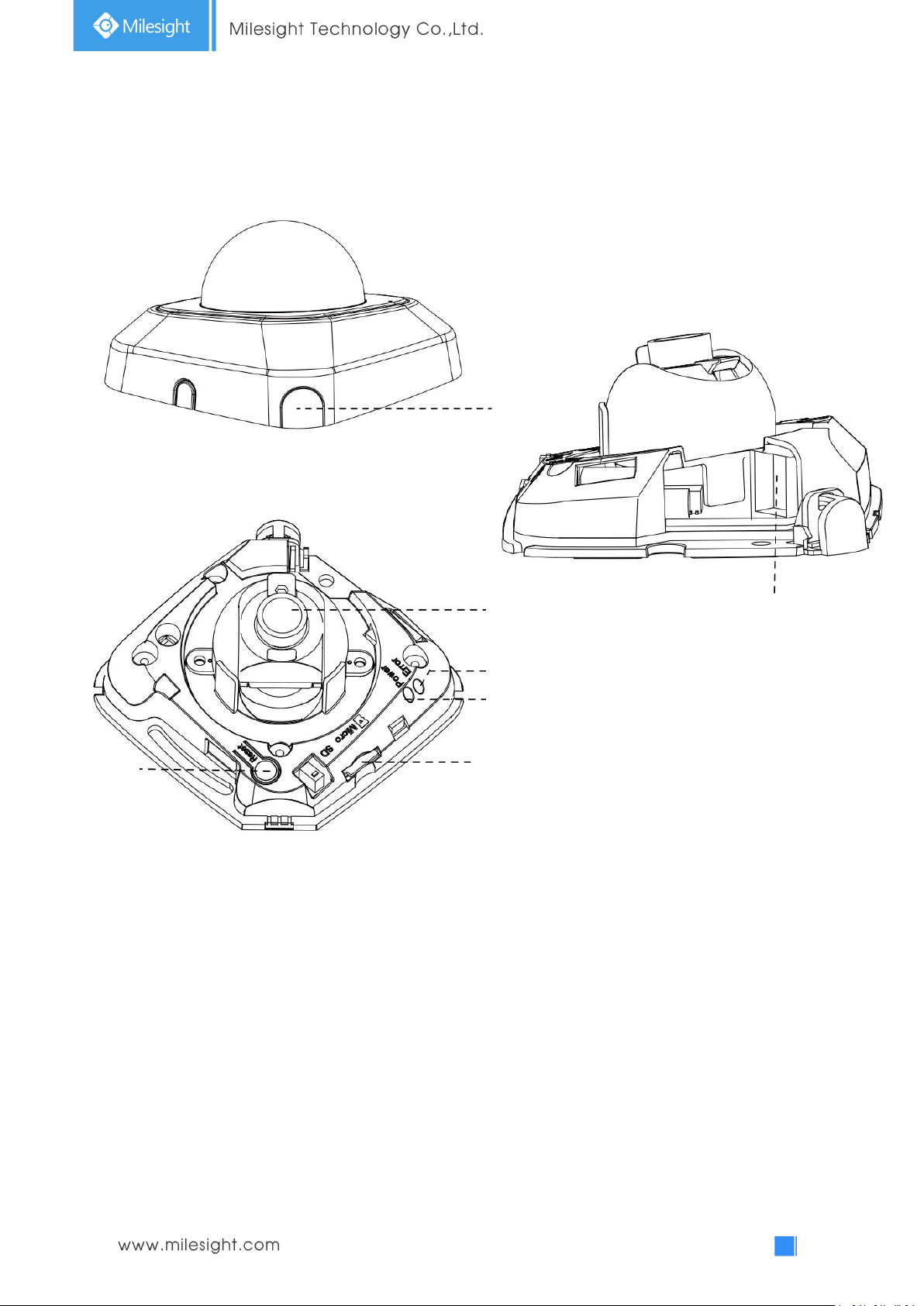
1.3 Hardware Overview
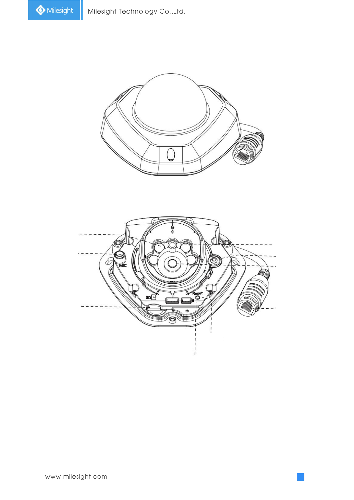
Press Button
Ethernet Port (PoE)
Lens
Error LED Indicator
Power LED Indicator
microSD/SDHC/SDXC Card Slot
Reset
1. Mini Dome Network Camera
Note:
1) Error LED Indicator: Error LED Indicator is on when the device starts up or runs error.
2) Reset Button: Press “Reset” button for 5 seconds, then the device will be restored to factory
default.
3) Only PoE is available for power supply.
Figure 1-3-1 Mini Dome Network Camera
3
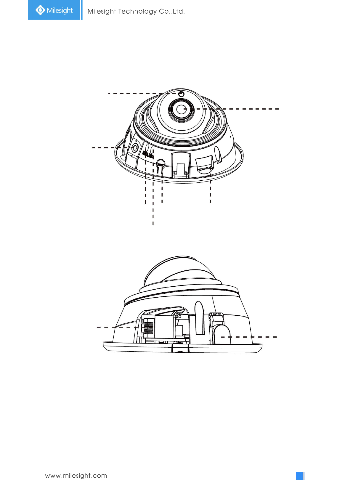
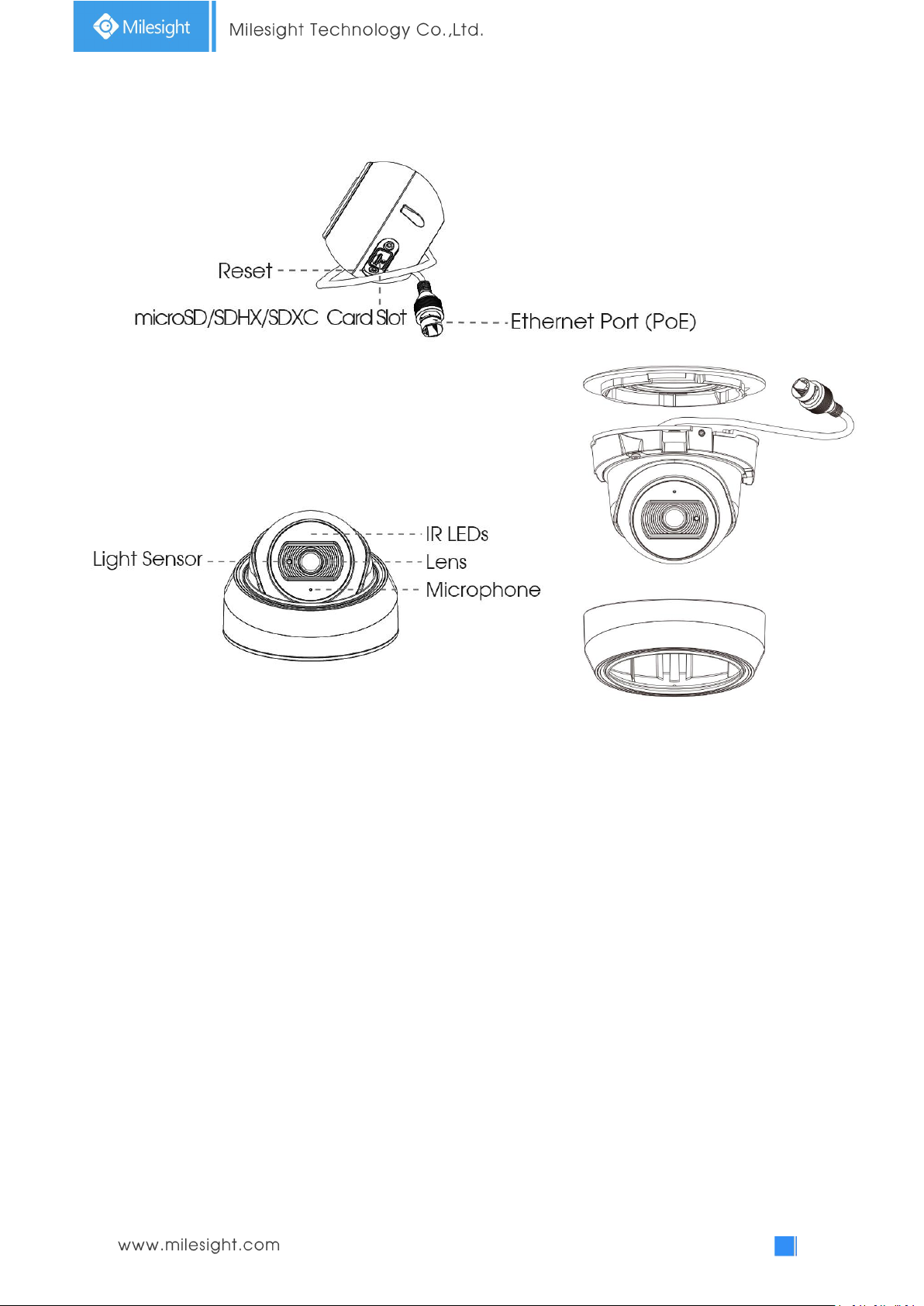
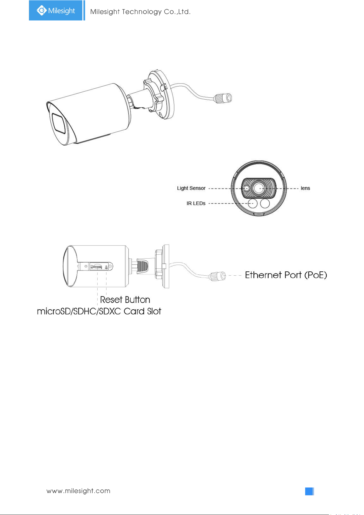
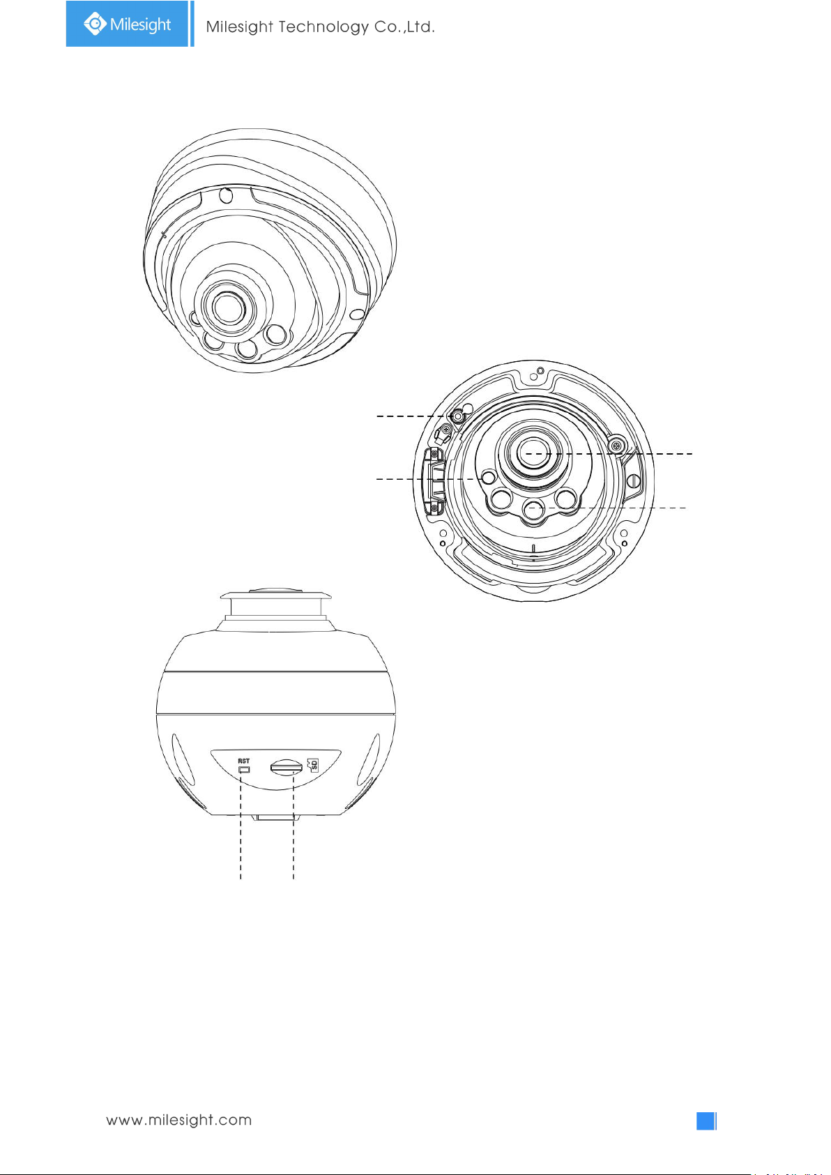
2. IR Mini Dome Network Camera
Ethernet Port (PoE)
Press Button
Light Sensor
Lens
Power LED Indicator
Error LED Indicator
Reset
microSD/SDHC/SDXC Card Slot
Microphone
Note:
1) Error LED Indicator: Error LED Indicator is on when the device starts up or runs error.
2) Reset Button: Press “Reset” button for 5 seconds, then the device will be restored to factory
default.
3) Only PoE is available for power supply.
Figure 1-3-2 IR Mini Dome Network Camera
4
3. Vandal-proof Mini Dome Network Camera
IR LEDs
Light Sensor
Lens
Ethernet Port (PoE)
microSD/SDHC/SDXC
Card Slot
Microphone
Screw
Power and System LED Indicator
Reset
Note:
1) Error LED Indicator: Error LED Indicator is on when the device starts up or runs error.
2) Reset Button: Press “Reset” button for 5 seconds, then the device will be restored to factory
default.
3) Only PoE is available for power supply.
Figure 1-3-3 Vandal-proof Mini Dome Network Camera
5
4. Weather-proof Mini Dome Network Camera
Figure 1-3-4 Weather-proof Mini Dome Network Camera
Note:
1) Reset Button: Press “Reset” button for 5 seconds, then the device will be restored to factory
default.
2) Only PoE is available for power supply.
6
5. AF Motorized Mini Dome Network Camera
Figure 1-3-5 AF Motorized Mini Dome Network Camera
Note:
1) Reset Button: Press “Reset” button for 5 seconds, then the device will be restored to factory
default.
2) DC 12V and PoE are available for power supply.
7
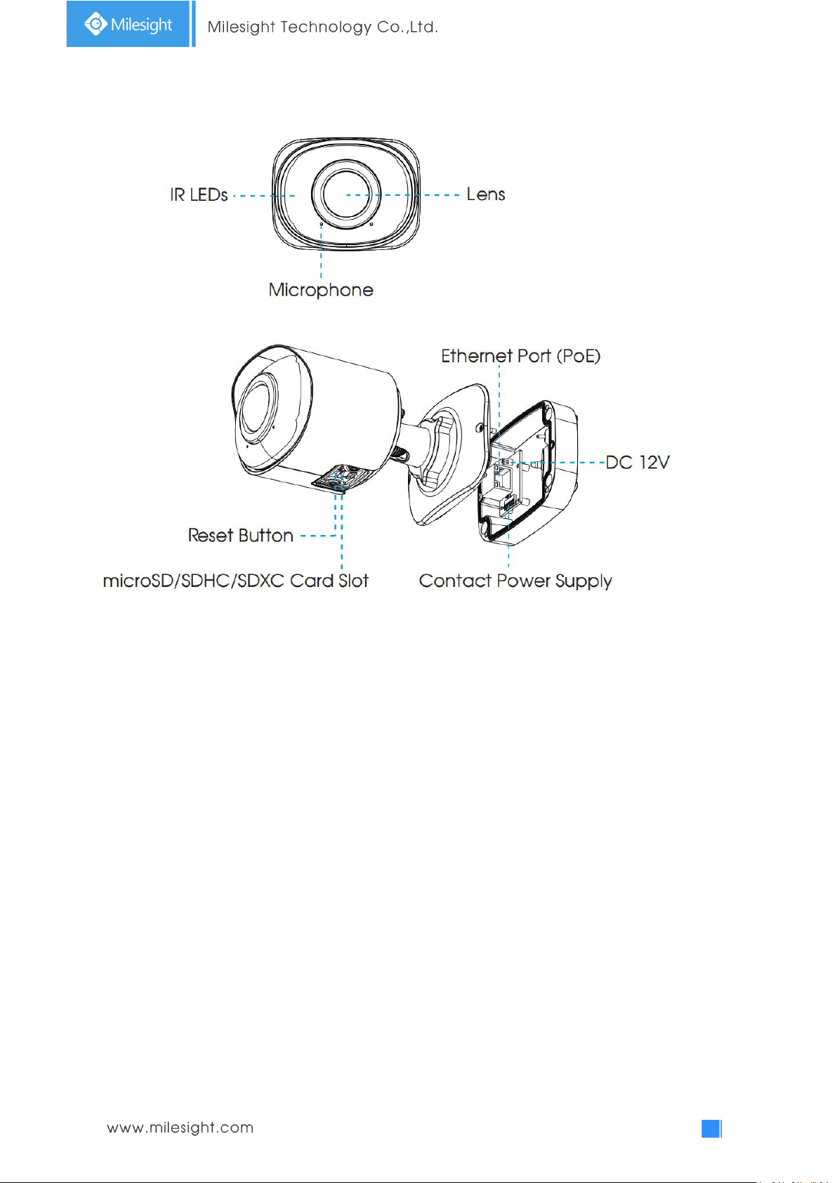
6. Mini Bullet Network Camera
Lens
IR LEDs
Light Sensor
Ethernet Port (PoE)
microSD/SDHC/SDXC Card Slot
Reset Button
Note:
1) Only PoE is available for power supply.
2) Reset Button: Press “Reset” button for 5 seconds, then the device will be restored to factory
default.
Figure 1-3-6 Mini Bullet Network Camera
8
7. Vandal-proof Mini Bullet Network Camera
Figure 1-3-7 Vandal-proof Mini Bullet Network Camera
Note:
1) Only PoE is available for power supply.
2) Reset Button: Press “Reset” button for 5 seconds, then the device will be restored to factory
default.
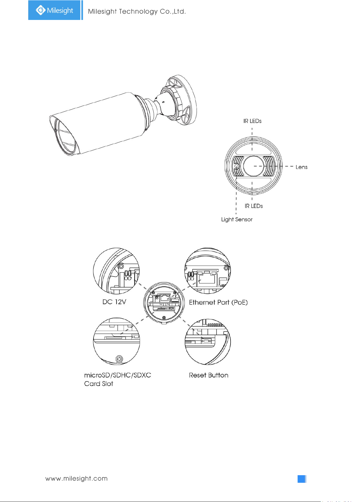
9
8. (Vandal-proof) Motorized Mini Bullet Network Camera
Ethernet Port (PoE)
Note:
1) DC 12V and PoE are available for power supply.
2) Reset Button: Press “Reset” button for 5 seconds, then the device will be restored to factory
Figure 1-3-8 (Vandal-proof) Motorized Mini Bullet Network Camera
default.
10
9. 180°Panoramic Mini Bullet Network Camera
Note:
1) PoE is available for power supply.
2) Reset Button: Press “Reset” button for 5 seconds, then the device will be restored to factory
default.
11
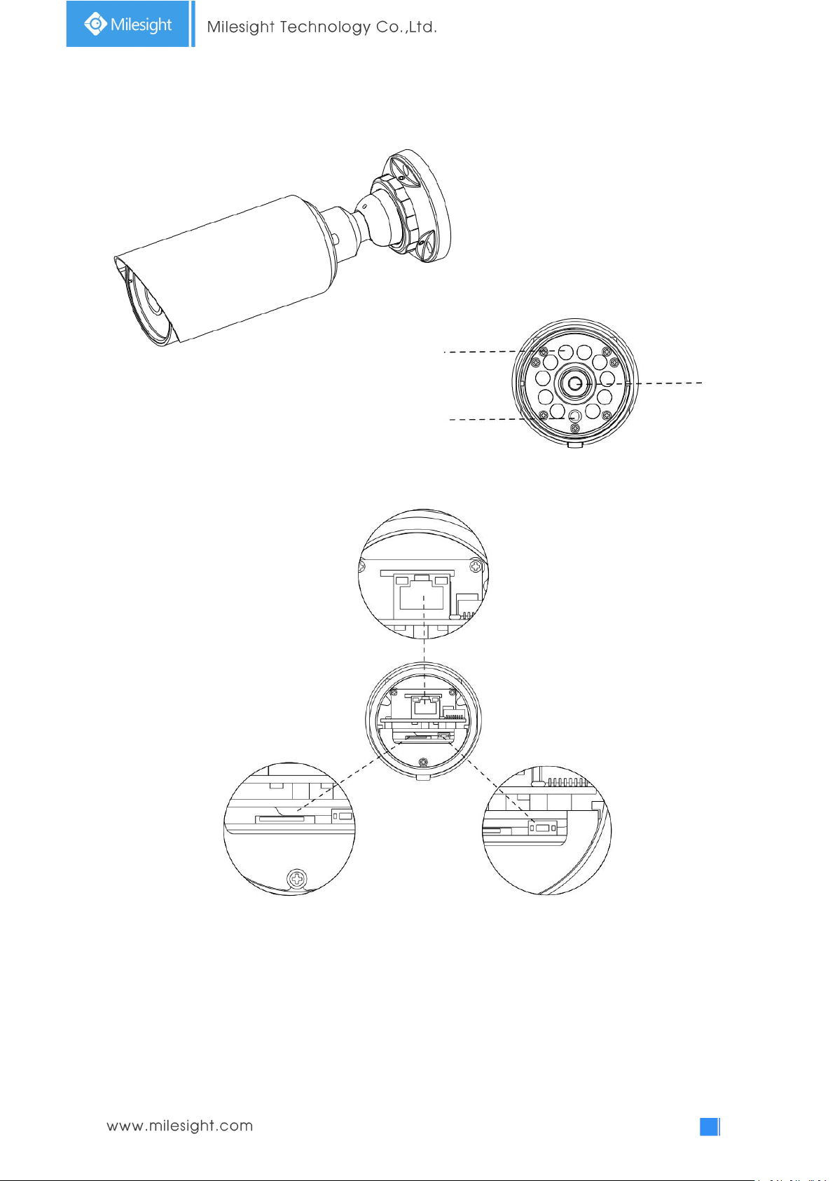
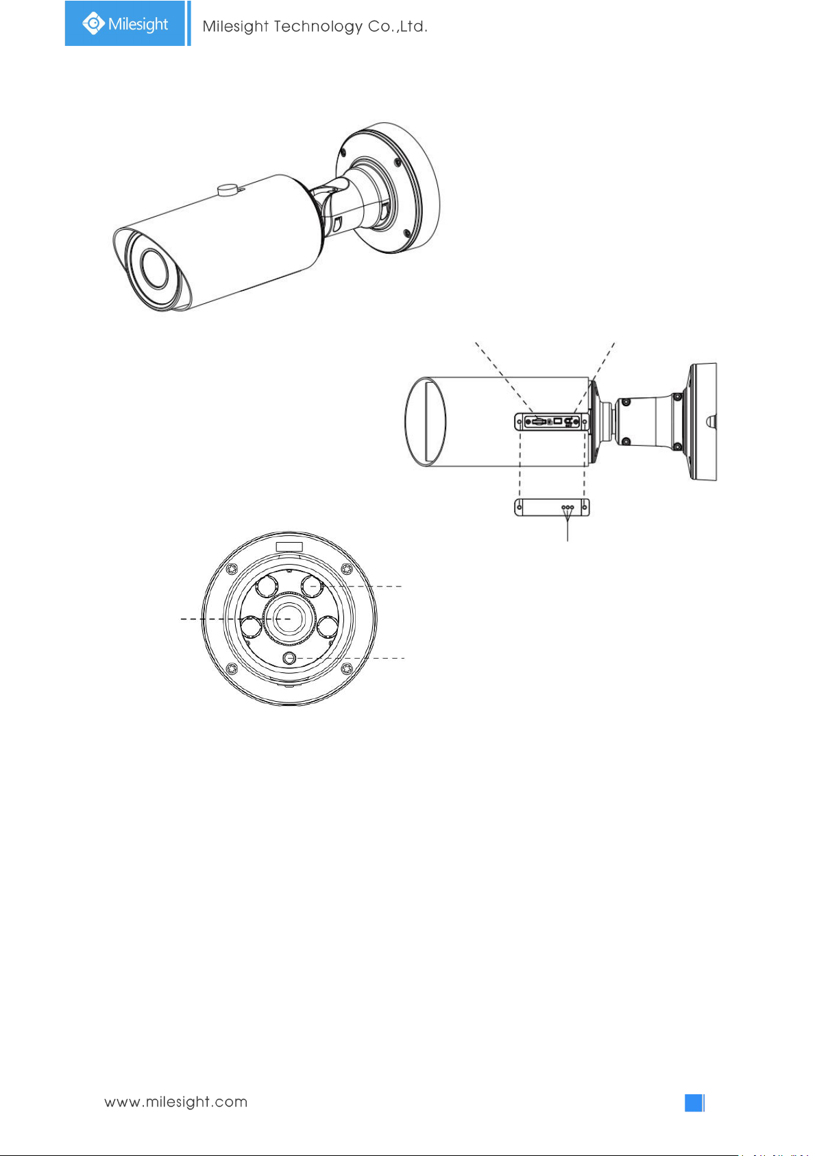
10. (12x AF) Motorized Pro Bullet Network Camera
microSD/SDHC/SDXC Card Slot
Reset
PTFE Membrane
IR LEDs
Lens
Light Sensor
Note:
3) DC 12V and PoE are available for power supply.
4) Reset Button: Press “Reset” button for 5 seconds, then the device will be restored to factory
default.
5) There are two versions for Pro Bullet: the interface’s pictures are as below.
Figure 1-3-9 (12x AF) Motorized Pro Bullet Network Camera
12
Figure 1-3-10 Motorized Pro Bullet Network Camera(Version A)
Ethernet Port (PoE)
DC 12V
DC 12V
Alarm/Audio
Ethernet Port
(PoE)
Alarm In/Out
Audio In/Out
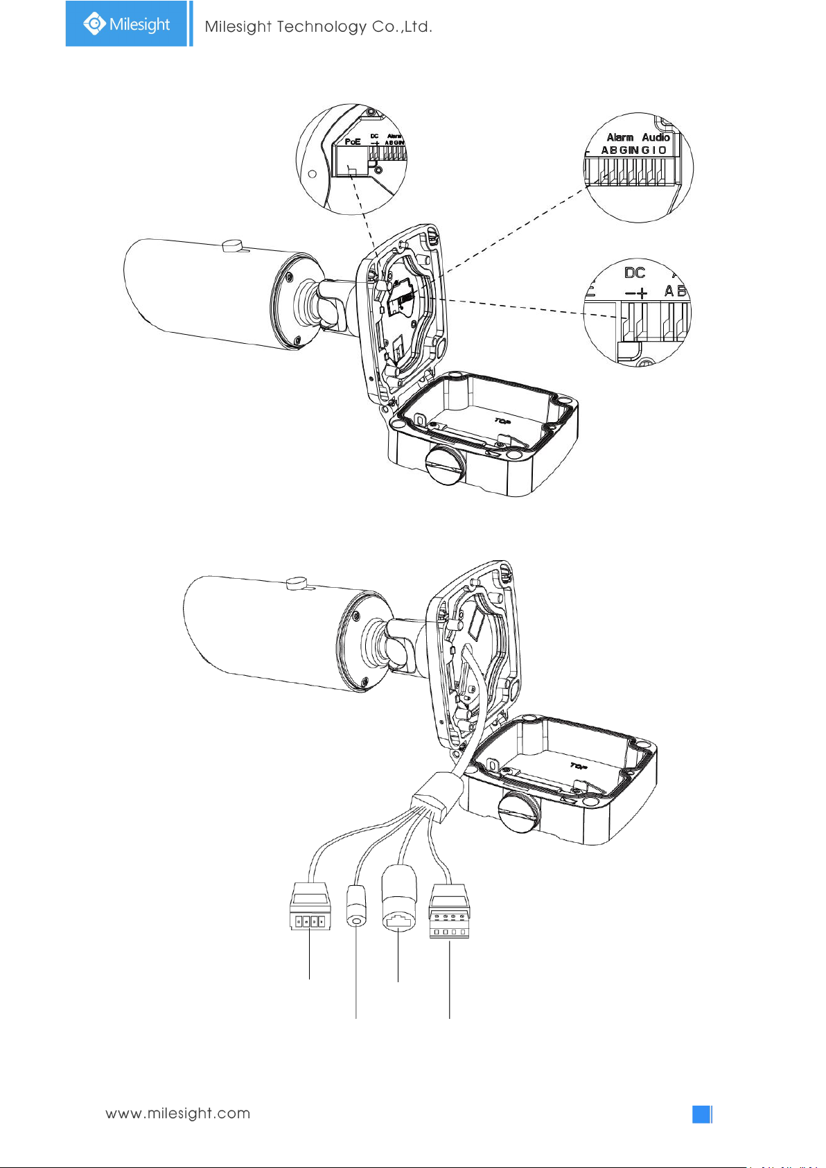
Figure 1-3-11 Motorized Pro Bullet Network Camera(Version B)
13
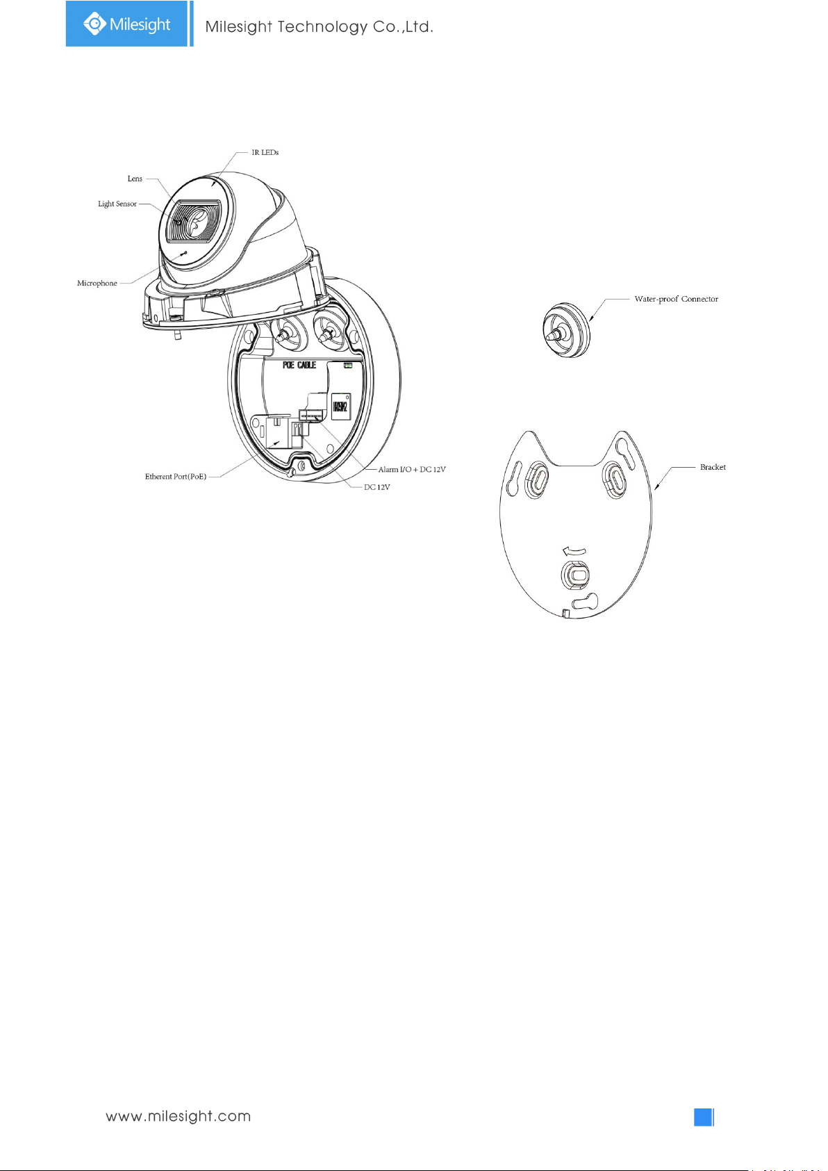
Microphone
Lens
IR LEDs
Light Sensor
Reset
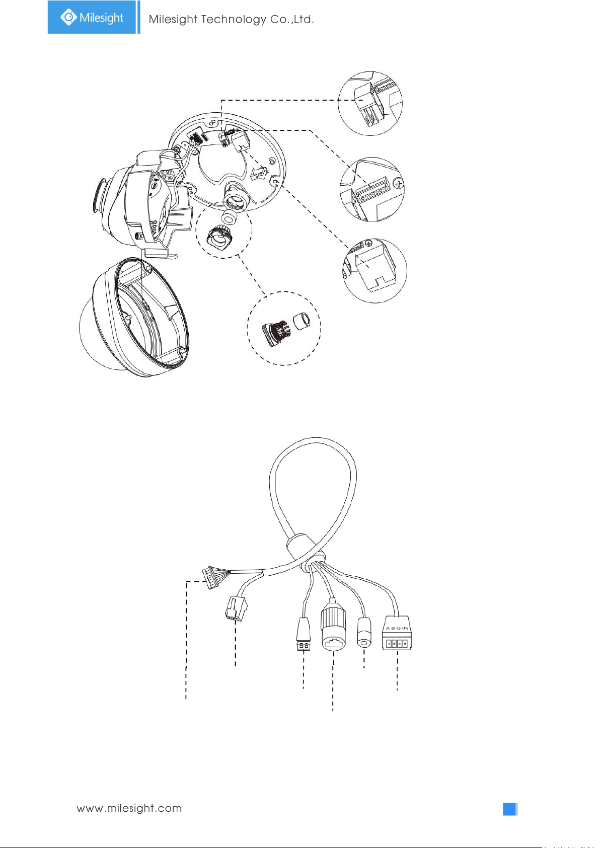
11. Motorized Pro Dome Network Camera
microSD/SDHC/SDXC Card Slot
Note:
1) Reset Button: Press “Reset” button for 5 seconds, then the device will be restored to factory
default.
Figure 1-3-12 Motorized Pro Dome Network Camera
14
DC 12V
Alarm In/Out & Audio Out/DC 12V
Ethernet Port
(PoE)
Ethernet Port
(PoE)
Figure 1-3-13 Motorized Pro Dome Network Camera multiple interface
Ethernet Port (PoE)
Water-proof Connector
Alarm In/Out &
Audio Out/DC 12V
Audio Out
DC 12V
Alarm In/Out
Here is one equipped cable for multiple interface usage:
Figure 1-3-14 Motorized Pro Dome Network Camera multiple interface cable
15
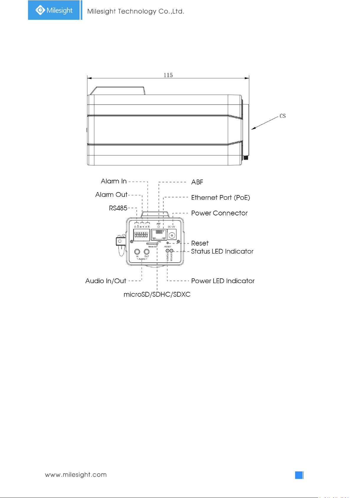
12. (LPR) (ABF) Pro Box Network Camera
Figure 1-3-15 (ABF) Pro Box Network Camera
Note:
1) Reset Button: Press “Reset” button for 5 seconds, then the device will be restored to factory
default.
2) DC 12V and PoE are available for power supply.
16
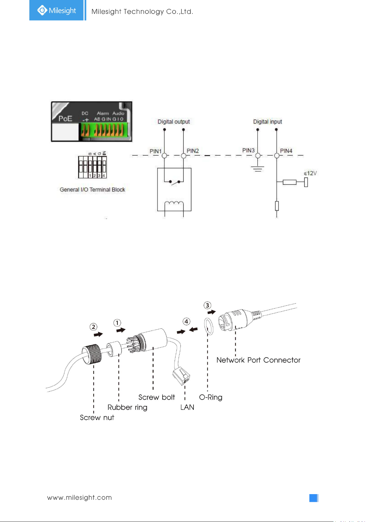
1.4 How to Connect to Alarm Interface
External interface of camera is as the following, you can refer to the picture to install the external
alarm device:
PIN1: Alarm Output NC/NO 24V DC 1A
PIN2: Alarm Output NC/NO 24V DC 1A
PIN3: Alarm Input NC/NO ≤12V
PIN4: Alarm Input NC/NO ≤12V
1.5 How to Connect the Water-proof Connector
Step1: Get the network cable through the screw nut, rubber ring and the screw bolt.
Step2: Insert the rubber ring into the screw bolt.
Step3: Connect the screw nut to the screw bolt.
Step4: Place the O-Ring on the network port connector.
Step5: Connect the RJ45 to the network port connector, and tighten the screw bolt and the
connector.

17
1.6 System Requirements
Operating System: Windows XP/Vista/7/8/10/Server 2000/Server 2008
CPU: 1.66GHz or higher
RAM: 1G or higher
Graphic memory: 128MB or more
Internet protocol: TCP/IP (IPv4/IPv6)
Web Browsers: Internet Explorer 8.0 and above version, Mozilla Firefox, Google Chrome and Safari.
18
Chapter II Network Connection
2.1 Setting the Camera over the LAN
Connecting the camera to a switch or a router is the most common connection method. The
camera must be assigned an IP address that is compatible with its LAN.
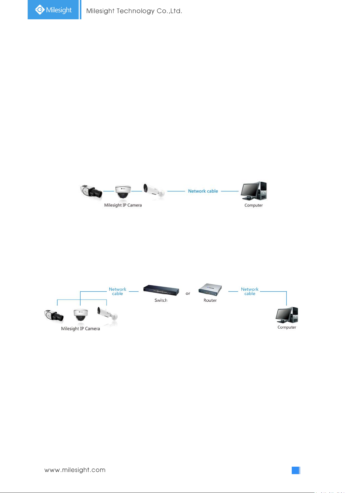
2.1.1 Connect the Camera to the PC Directly
In this method, only the computer connected to the camera will be able to view the camera. The
camera must be assigned a compatible IP address to the computer. Details are shown as the
following figure.
Figure 2-1-1 Connect the camera to the PC directly
2.1.2 Connect via a Switch or a Router
Refer to the following figure to set network camera over the LAN via the switch or router.
Figure 2-1-2 Connect via a switch or a Router
2.2 Dynamic IP Connection
Connecting the network camera via a router
Step1: Connect the network camera to a router;
Step2: On the camera, assign a LAN IP address, the Subnet mask and the Gateway;
Step3: On the router, set port forwarding. E.g. 80, 8000 and 554 ports. The steps for port
forwarding vary depending on different routers. Please look up the router's user manual for
assistance with port forwarding;
Step4: Apply a domain name from a domain name provider;

19
Step5: Configure the DDNS settings in the setting interface of the router;
Step6: Visit the camera via the domain name.
Figure 2-2 Connect the network camera via a router using dynamic IP
20
Chapter III Accessing the Network Camera
The camera must be assigned an IP address to be accessible.
3.1 Assigning An IP Address
The Network Camera must be assigned an IP address to be accessible. The default IP address of
Milesight Network Camera is 192.168.5.190.
You can either change the IP address of the camera via Smart Tools or browser. Please connect the
camera in the same LAN of your computer.
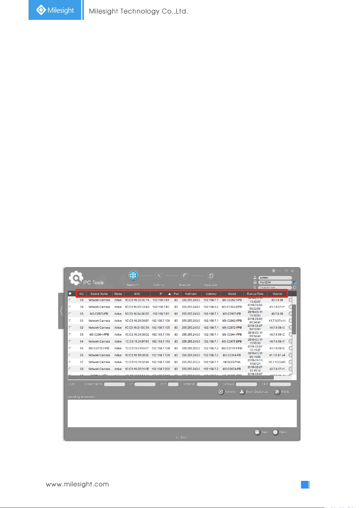
3.1.1 Assigning An IP Address Using Smart Tools
Smart Tools is a software tool which can automatically detect multiple online Milesight network
cameras in the LAN, set IP addresses, and manage firmware upgrades. It’s recommended to use
when assigning IP addresses for multiple cameras.
Step1: Install Smart Tools (The software could be downloaded from our website);
Step2: Start Smart Tools, click the IPC Tools page, then enter the device information, such as IP
address, MAC address, Status, Port number, Netmask, and Gateway, then all related
Milesight network cameras in the same network that will be displayed. Details are shown as
shown below;
21
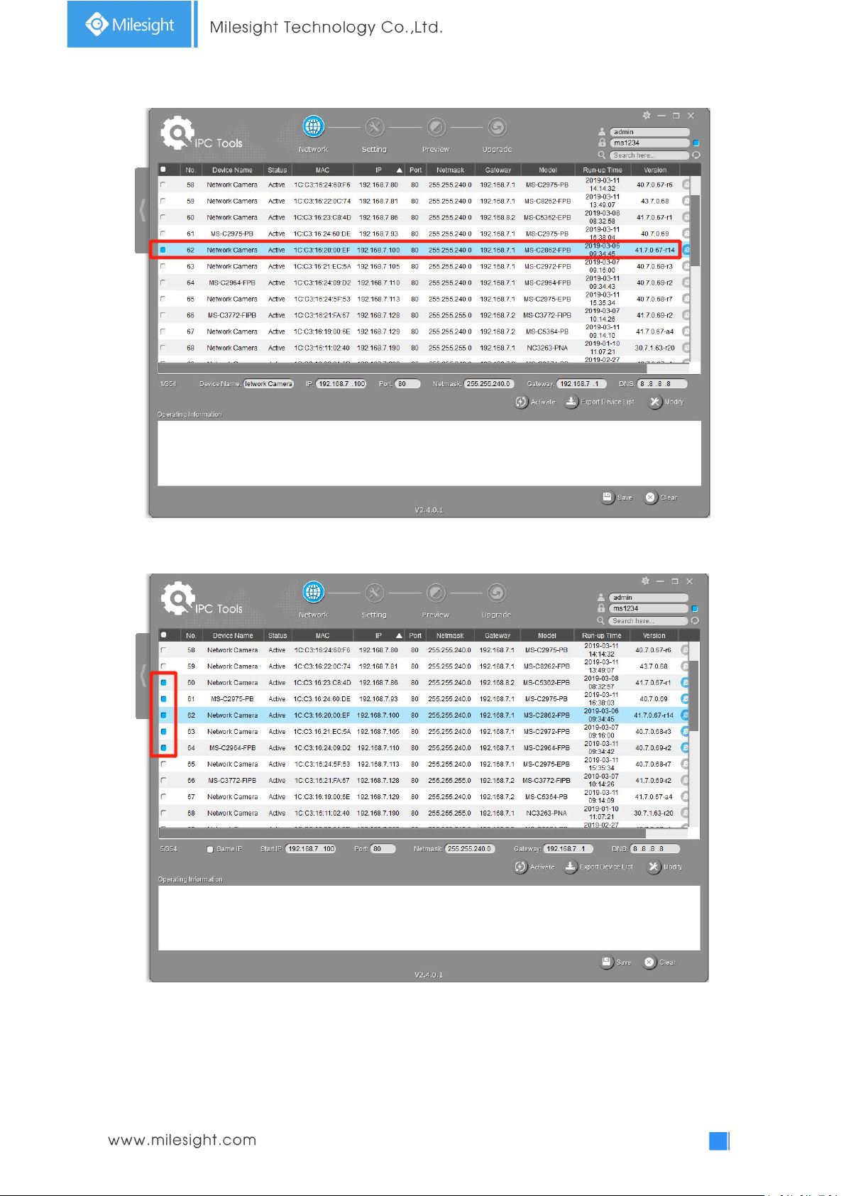
Step3: Select a camera or multiple cameras according to the MAC addresses;
Select single camera
Select multiple cameras
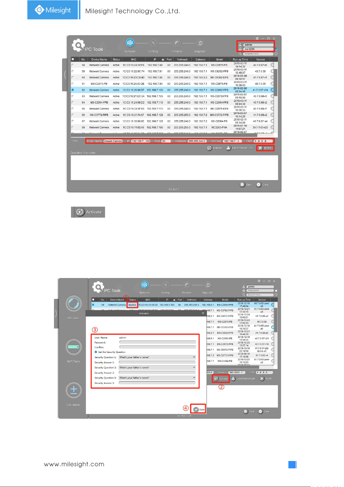
Step4: If the selected camera shows "Active" in the status bar, you can directly type the User Name
and Password (Camera with version lower than 4x.7.0.69 is using admin/ms1234 by default),
change the IP address or other network values, and then click “Modify” button;
22
If the selected camera shows "Inactive" in the status bar(Camera with version V4x.7.0.69 or
above), click to set the password when using it for the first time. You can also set the
security questions when activating the camera in case that you forget the password(You can reset
the password by answering three security questions correctly). Click ‘Save’ and it will show that the
activation was successful.
Note:
(1) Password must be 8 to 32 characters long, contain at least one number and one letter.
(2) You need to upgrade Smart Tools version to V2.4.0.1 or above to activate the camera.
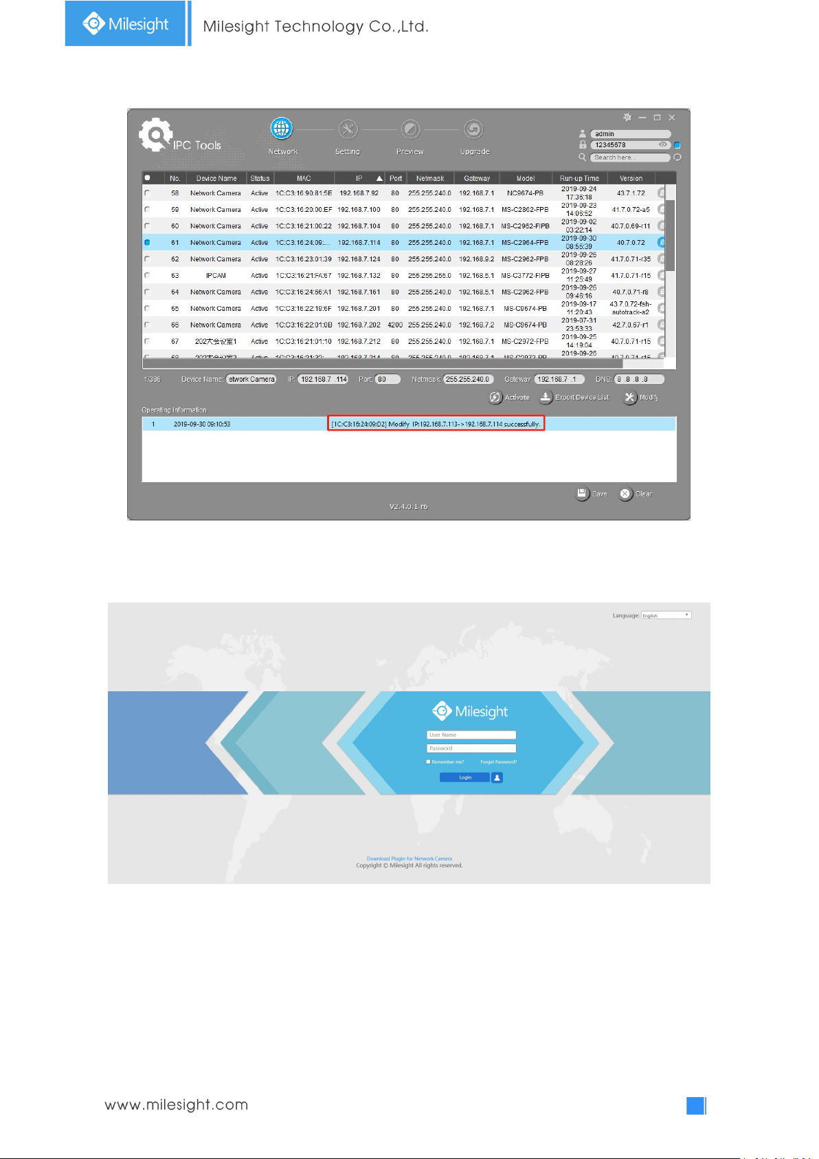
After activation, you can change the IP address or other network values, and then click “Modify”
button.
23
Step5: Change the IP address successfully;
Step6: By double clicking the selected camera or the browser of interested camera, you can access
the camera via web browser directly. The Internet Explorer window will pop up.
More usage of Smart Tools, please refer to the Smart Tools User Manual.
3.1.2 Assign An IP Address via Browser
If the network segment of the computer and that of the camera are different, please follow the
24
steps to change the IP address:
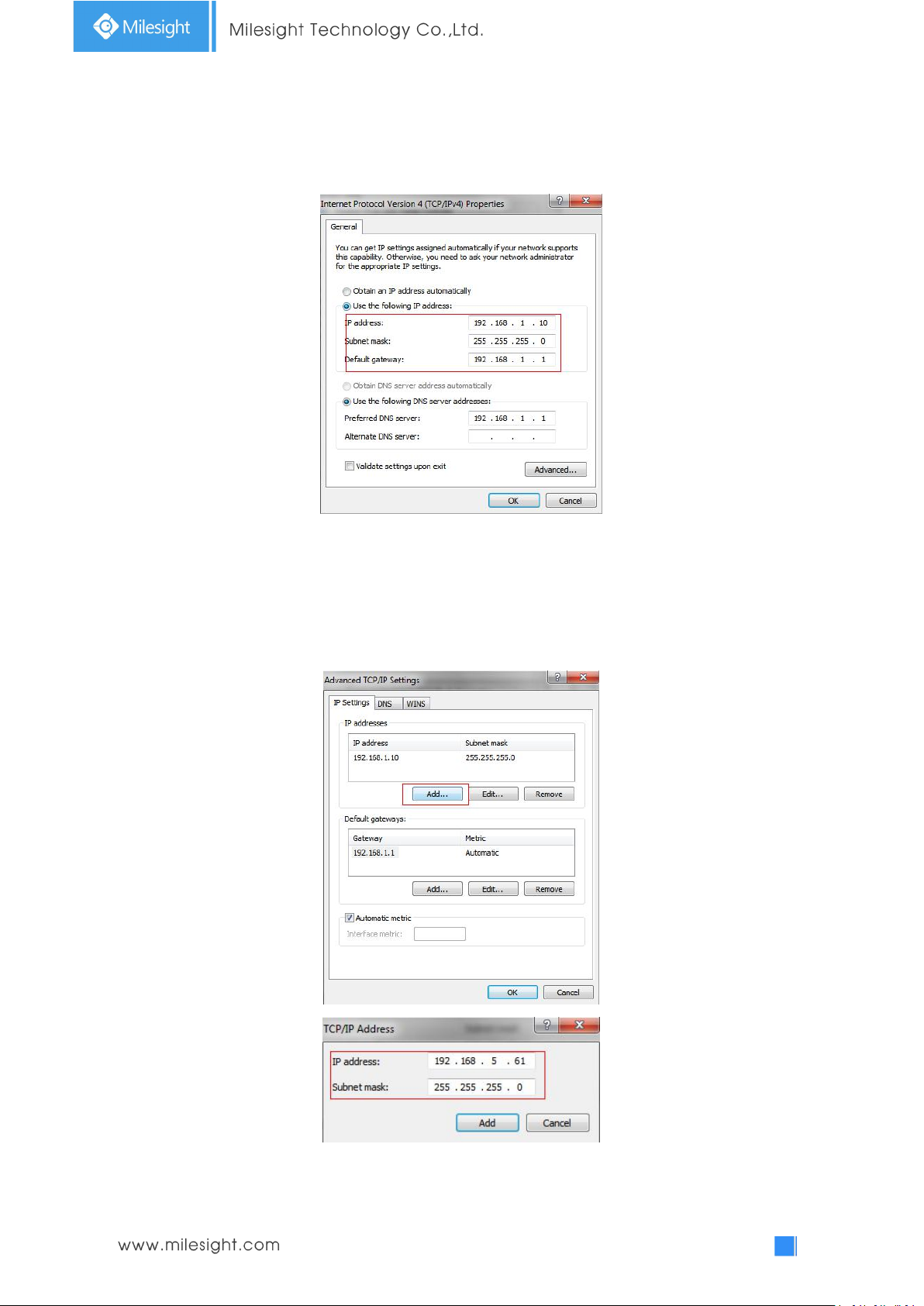
Step1: Change the IP address of computer to 192.168.5.0 segment, here are two ways as below:
a. StartControl PanelNetwork and Internet ConnectionNetwork Connection
Local Area Connection, and double click it. (Refer to Figure 3-1-8);
Figure 3-1-8 Setting Network Segment IP Address of Computer
b. Click “Advanced”, and then click “IP settings”“IP address”“Add” (See Figure
3-1-9). In the pop-up window, enter an IP address that in the same segment with
Milesight network camera ( e.g. 192.168.5.61, but please note that this IP address
shall not conflict with the IP address on the existing network);
Step2: Start the browser. In the address bar, enter the default IP address of the camera:
http://192.168.5.190;
25
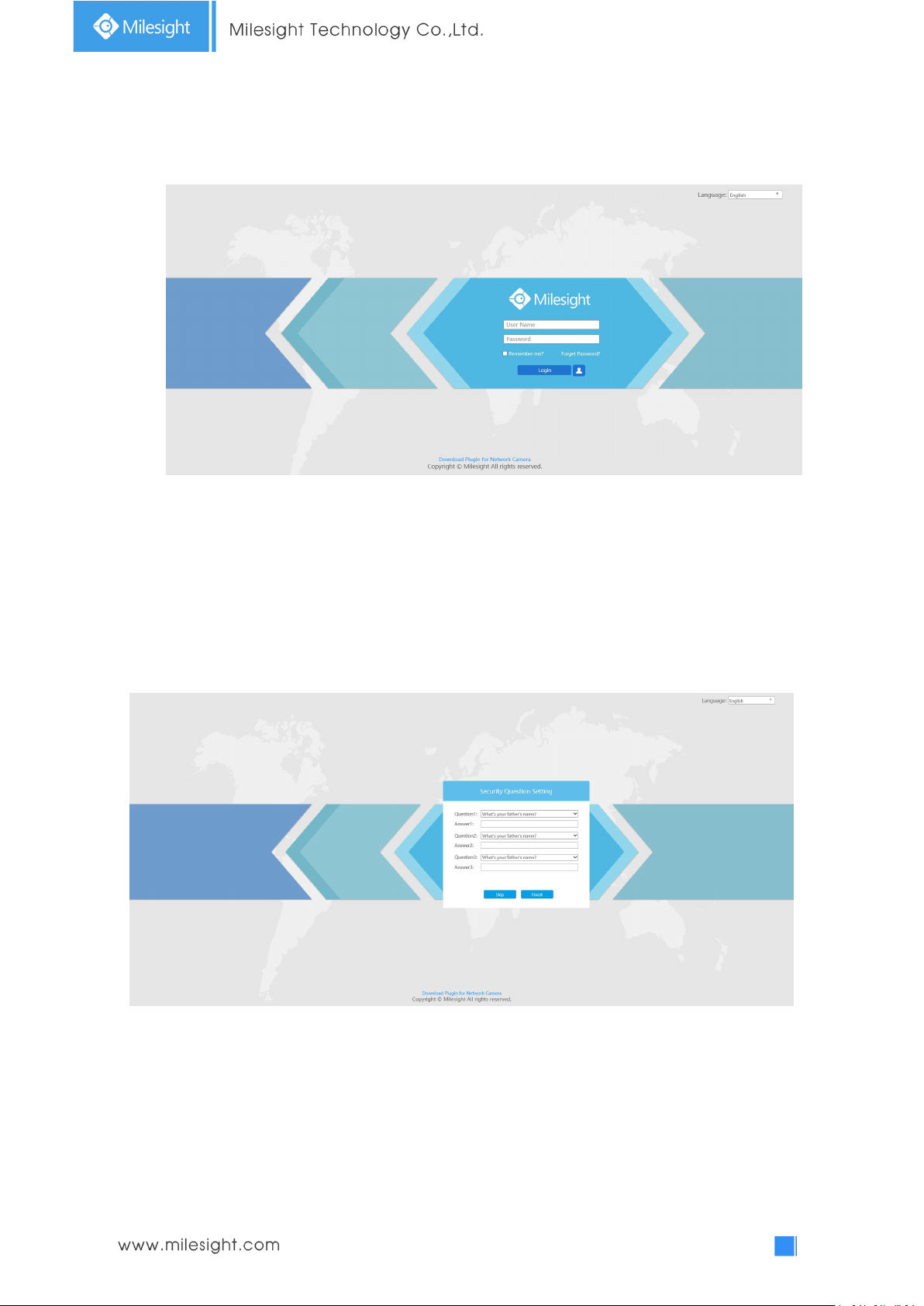
Step3: If the camera’s firmware version is lower than V4x.7.0.69, it will directly display the login
page, enter the user name and password when the LOGIN page appears;
Default user name: admin
Default password: ms1234
If the camera’s firmware version is V4x.7.0.69 or above, you need to set the password first
when using it for the first time. And you can also set three security questions for your device
after activation. Then, you can log in the device with You can log in to the camera with the
username(admin) and a custom password.
Note:
(1) Password must be 8 to 32 characters long, contain at least one number and one letter.
(2) You can click the “forget password” in login page to reset the password by answering three security
questions when you forget the password, if you set the security questions in advance.
Step4: After login, please select “Configuration”“Basic Settings”“Network”“TCP/IP”. The
Network Settings page appears (Shown as below Figure);
 Loading...