

Milesight MS-C3586, MS-C2181, MS-C2681, MS-C3581, MS-C3688 User Manual
...
Version: V4.03

User Manual
1
About this Document
This Manual explains how to use and manage Milesight network cameras on your network.
Previous experience of networking will be of use when using the products. This manual applies to
the following camera models, except where otherwise indicated.
Please read this manual carefully before operation and retain it for future reference.
Copyright Statement
This manual may not be reproduced in any form or by any means to create any derivative such
as translation, transformation, or adaptation without the prior written permission of Milesight
Technology Co., Ltd(Hereinafter referred to as Milesight).
Milesight reserves the right to change this manual and the specifications without prior notice.
The latest specifications and user documentation for all Milesight products are available on our
official website www.milesight.com
Warnings Serious injury or death may be caused if any of these warnings are neglected.
Cautions Injury or equipment damage may be caused if any of these cautions are neglected.
Warnings Please follow these safeguards to
prevent injury or death.
Megapixel
Type
1.3MP
2MP
3MP
5MP
Mini Dome Camera
MS-C2181
MS-C2681
MS-C3581
MS-C3586
MS-C3688
IR Mini Dome Camera
MS-C2182
MS-C2682
MS-C3582
MS-C3587
MS-C3689
Box Camera
MS-C2151
-
MS-C3356
MS-C3658
Mini Bullet Camera
MS-C2163
MS-C3263
MS-C3363
MS-C3567
MS-C3367
-
IR Dome Camera
MS-C2172
MS-C3272
MS-C3372
MS-C3376
MS-C3576
-
Varifocal IR Dome Camera
MS-C2172-V
MS-C3272-V
MS-C3372-V
MS-C3576-V
MS-C3376-V
--
Varifocal Bullet Camera
MS-C2162-V
MS-C3262-V
MS-C3362-V
MS-C3566-V
MS-C3366-V
-
Remote Focus Zoom Bullet Camera
MS-C2162-F
MS-C3262-F
MS-C3362-F
MS-C3566-F
MS-C3366-F
Cube Camera
MS-C2191
MS-C3291
MS-C3596
-
User Manual
2
Cautions Please follow these precautions to
prevent potential injury or material damage.
Warning
This installation must be conducted by a qualified service person and should strictly
comply with the electrical safety regulations of the local region
To avoid risk of fire and electric shock, do keep the product away from rain and moisture
Do not touch components such as heat sinks, power regulators, and processors, which
may be hot
Source with DC 12V or PoE
Please make sure the plug is firmly inserted into the power socket
When the product is installed on a wall or ceiling, the device should be firmly fixed
If the product does not work properly, please contact your dealer. Never attempt to
disassemble the camera yourself
Cautions
Make sure that the power supply voltage is correct before using the camera
Do not store or install the device in extremely hot or cold temperatures, dusty or damp
locations, and do not expose it to high electromagnetic radiation
Only use components and parts recommended by manufacturer
Do not drop the camera or subject it to physical shock
To prevent heat accumulation, do not block air circulation around the camera
Laser beams may damage image sensors. The surface of image sensors should not be
exposed to laser beam where a laser beam equipment is used
Use a blower to remove dust from the lens cover
Use a soft, dry cloth to clean the surface of the camera. Stubborn stains can be removed
using a soft cloth dampened with a small quantity of detergent solution, then wipe dry
Do not use volatile solvents such as alcohol, benzene or thinners as they may damage the
surface finishes
Save the package to ensure availability of shipping containers for future transportation
Environmental Protection
Please recycle this device in a responsible manner. Refer to local environmental regulations for
proper recycling. Do not dispose of devices in unsorted municipal waste.

User Manual
3
Table of Contents
Chapter I Product Description ......................................................................................................... 5
1.1 Product Overview ............................................................................................................... 5
1.2Key Features ........................................................................................................................ 5
1.3 Hardware Overview ............................................................................................................ 6
1.4 Hardware Installation ......................................................................................................... 9
1.5 System Requirements ....................................................................................................... 13
Chapter II Network Connection ..................................................................................................... 14
2.1 Setting the camera over the LAN ...................................................................................... 14
2.1.1 Connect the camera to the PC directly .................................................................... 14
2.1.2 Connect via a Switch or a Router ............................................................................. 14
2.2 Setting the camera over the WAN ..................................................................................... 15
2.2.1 Static IP Connection ................................................................................................ 15
2.2.2 Dynamic IP Connection ........................................................................................... 15
Chapter III Accessing the Network Camera .................................................................................... 17
3.1 Assigning An IP Address .................................................................................................... 17
3.1.1 Assigning An IP Address Using IPCTools ................................................................... 17
3.1.2 Assign An IP Address Manually ................................................................................ 20
3.2 Accessing from the Web Browser ..................................................................................... 23
3.2.1 Access over IE Browser ............................................................................................ 23
3.3 Accessing from Milesight VMS (Video Management Software) ......................................... 26
Chapter IV System Operation Guide .............................................................................................. 28
4.1 Live Video ......................................................................................................................... 28
4.2Basic Settings..................................................................................................................... 30
4.2.1 Video ...................................................................................................................... 30
4.2.2 Image ...................................................................................................................... 31
4.2.3 Audio ...................................................................................................................... 33
4.2.4Network ................................................................................................................... 34
4.2.5 Wi-Fi* ..................................................................................................................... 35
4.2.6Date &Time.............................................................................................................. 36
4.3Advanced Settings ............................................................................................................. 36
4.3.1SIP ........................................................................................................................... 36
4.3.2UPNP ....................................................................................................................... 38
4.3.3 DDNS ...................................................................................................................... 39
4.3.4SMTP ....................................................................................................................... 39
4.3.5FTP........................................................................................................................... 40
4.3.6Alarm ....................................................................................................................... 41
4.3.7Privacy Masking ....................................................................................................... 42
4.3.8 SD Card ................................................................................................................... 43
4.3.9 PTZ .......................................................................................................................... 44
4.3.10 User ...................................................................................................................... 44
4.3.11 Access List ............................................................................................................. 45

User Manual
4
4.3.12 Logs ...................................................................................................................... 46
4.4System ............................................................................................................................... 46
4.5Maintenance ..................................................................................................................... 47
Chapter V Services ........................................................................................................................ 48

User Manual
5
Chapter I Product Description
1.1 Product Overview
Milesight provides a consistent range of cost-effective and reliable network cameras to fully
meet your requirements. Based on embedded LINUX operating system, Milesight network
cameras could be easily accessed and managed either locally or remotely with great reliability.
With the TI DaVinci processor and built-in high-performance DSP video processing modules, the
cameras pride on low power consumption and high stability. They support state-of-the-art H.264
video compression algorithm and industry-leading HD dual-stream technology to achieve the
highest level of video image quality under the limited network resources. It is fully functional,
supporting for flexible and comprehensive alarm linkage mechanism, day and night auto switch,
smart PTZ control and privacy masking, etc.
In practical applications, Milesight network camera could either work independently in the local,
or be networked to form a powerful safety monitoring system. It is widely used in fields such as
finance, education, industrial, civil defense, health care for security’s sake.
1.2 Key Features
Based on LINUX OS with high reliability
H.264/MPEG-4/MJPEG video compression capability
G.711/AAC audio compression capability
Support ONVIF, PSIA protocol
Dual-stream
Power over Ethernet
Audio input/output, alarm input/output(built-in for box cameras, optional for bullet and
dome cameras)
IR cut filter with auto switch, true day/night
Built-in WEB server, support IE/Firefox/Chrome/Safari browser
Real-time video electronic amplification
Three-privilege levels of users for flexible management
SD/SDHC card local storage support, expand the edge storage(applicable for box and
Dome cameras)
Local PAL/NTSC signal output
Standard RS-485 interface, multiple PTZ control protocol
Motion detection, privacy masking, network fault detection and image snapping
UPNP protocol for the easy management of IPC
True Wide Dynamic Range (Optional feature according to the model selected)
User Manual
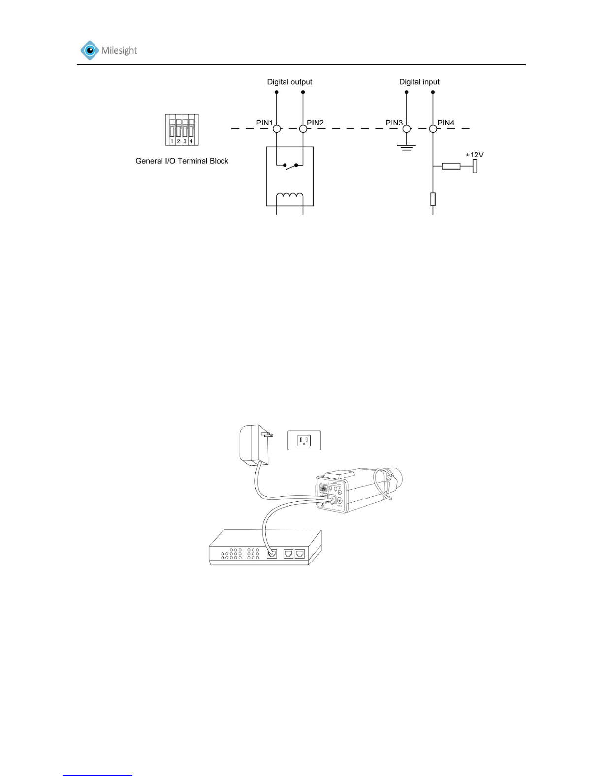
1.3 Hardware Overview
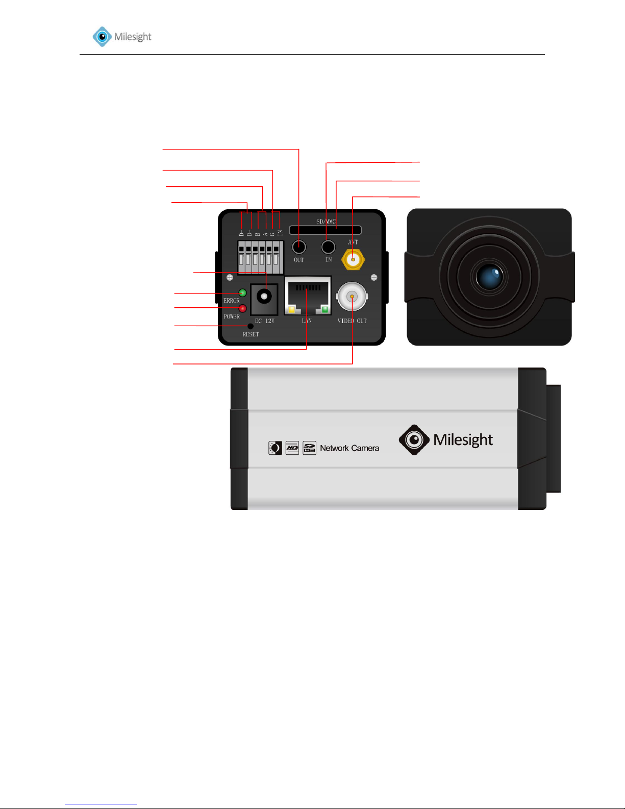
1. Box Camera
Figure1-1
*Note:
1) Error LED: Error LED is on when the device starts up or runs error.
2) Reset Button: Press ‘Reset’ button for 5 seconds, the device will be restored to factory default.
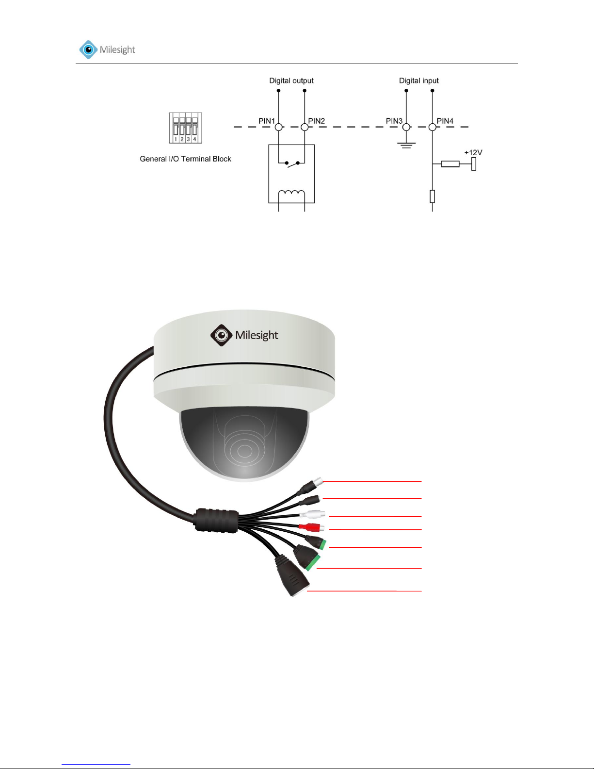
3) The network camera provides a general I/O terminal block which is used to connect external
input/output devices. Please refer to the following instruction for the connection method.
*Error LED
Power LED
*Reset Button
Ethernet Port
BNC Video Out
Power Connector (DC12V)
Alarm Output
RS-485 PTZ control
Alarm Input
Antenna for WIFI (Optional)
Audio Input
SD/SDHC Card Slot
Audio Output
User Manual
7
Figure1-2
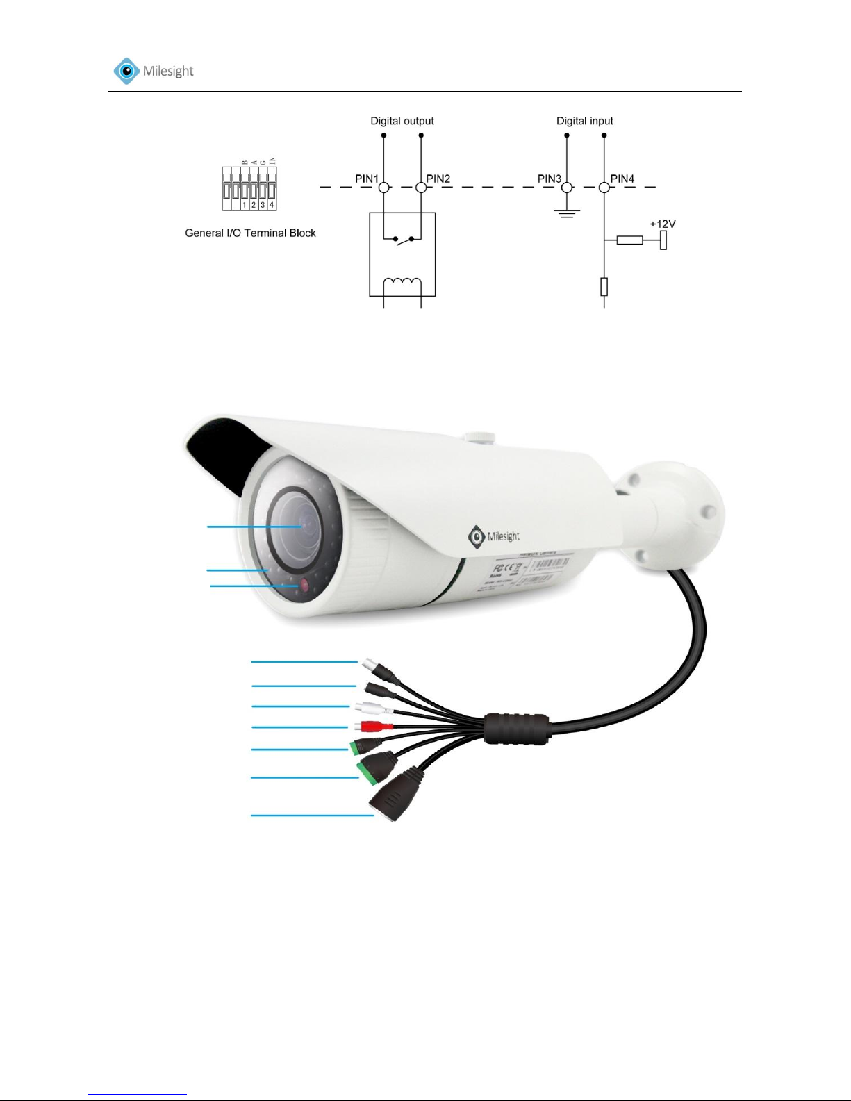
2. Bullet Camera
Figure 1-3
*Note:
1) The network camera provides a general I/O terminal block which is used to connect external
input/output devices. Please refer to the following instruction for the connection method.
Power Connector (DC 12V)
Alarm Input/ Output
RS-485 PTZ control
Ethernet Port
Lens
Video Output
Light Sensor
IR LED
Audio Output
Lens
Audio Input
User Manual
8
Figure 1-4
3. Dome Camera
Figure 1-5
*Note:
1) The network camera provides a general I/O terminal block which is used to connect external
input/output devices. Please refer to the following instruction for the connection method.
Video Output
Power Connector (DC 12V)
Audio Output
Audio Input
RS-485 PTZ control
Alarm Input/ Output
Ethernet Port
User Manual
9
Figure 1-6
1.4 Hardware Installation
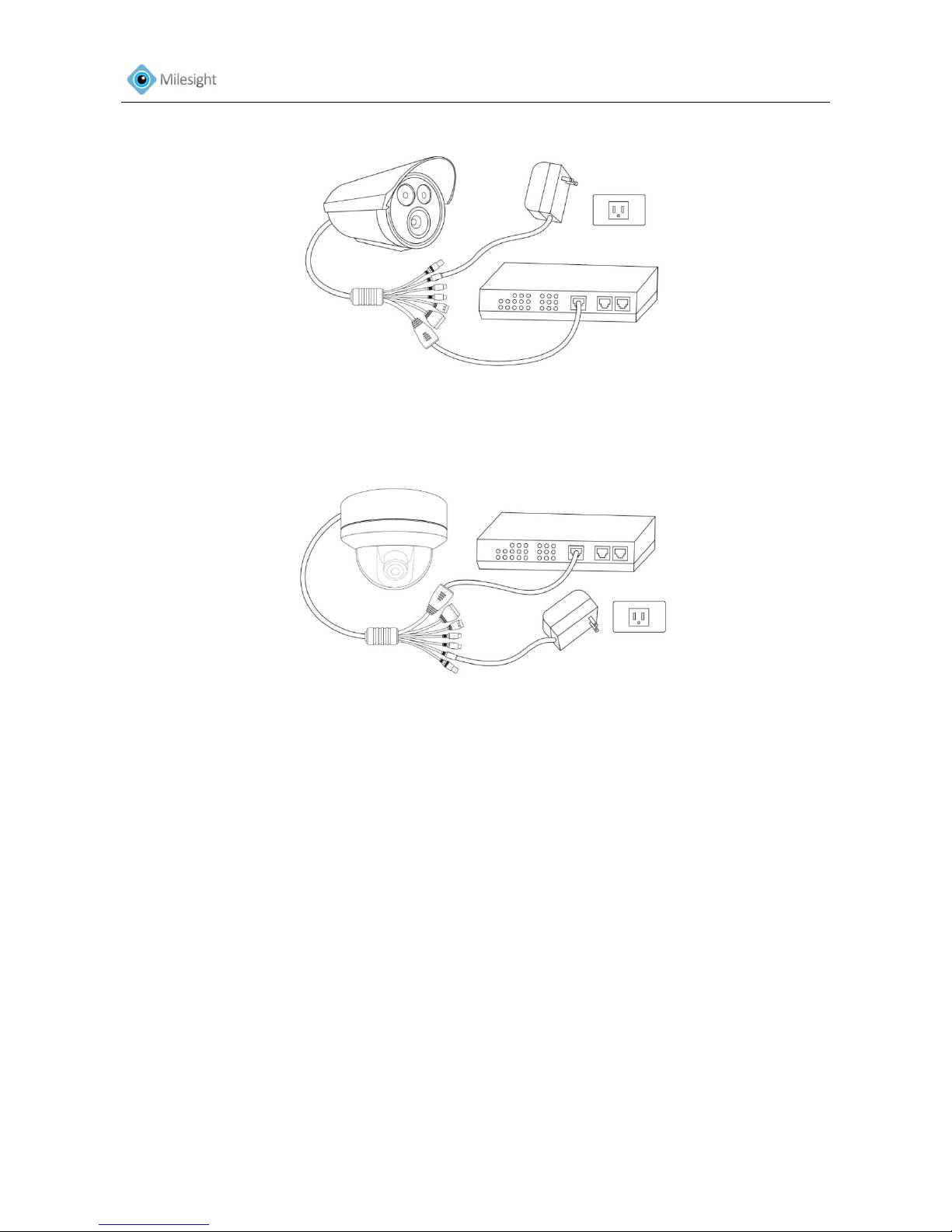
1. Connect the camera to the network and power using one of the methods listed below:
1) Basic connection (without PoE):
Step 1: connect the DC 12V end of the power adapter to the power port of the camera and
connect the other end to a wall outlet;
Step 2: connect the camera to a switch using an Ethernet cable.
Figure 1-7 Box Camera
User Manual
10
Figure 1-8 Bullet Camera
Figure1-9 Dome Camera
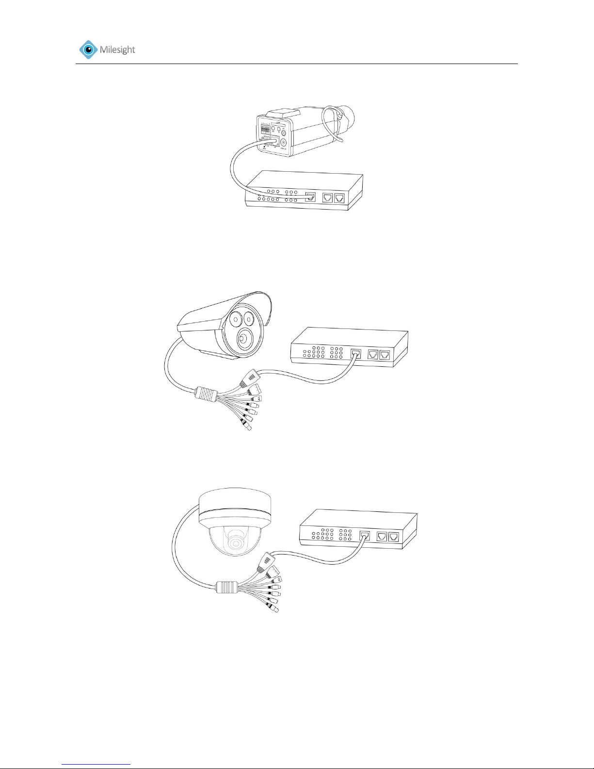
2) Power over Ethernet (PoE) connection. PoE will be automatically detected when the Ethernet
cable is connected. The camera can either be connected to a PoE-enabled switch or a non-PoE
switch.
A. Connect the camera to a PoE switch using a single Ethernet cable.
User Manual
11
Figure 1-10Box Camera
Figure 1-11 Bullet Camera
Figure 1-12 Dome Camera
B. Connect the camera to a non-PoE switch using the PoE injector
Step 1: Connect the camera to a PoE injector using an Ethernet cable.
Step 2: Connect the PoE injector to the non-PoE switch using an Ethernet cable.
Step 3: Connect the PoE injector to a power outlet.

User Manual
12
Figure 1-13Box Camera
Figure 1-14 Bullet Camera
Figure 1-15Dome Camera
The power LED will light steady red when the camera is connected to a power source
2. Optionally connect external input/output devices, such as alarm devices.
3. Optionally connect an active speaker or external microphone.
4. Optionally connect the camera to a monitor using a BNC cable.

User Manual
13
1.5 System Requirements
OS: Windows XP/7/Vista/Server 2000/Server 2008(Please use IE browser/Chrome/Firefox to
operate)
CPU: 1.66GHz or higher
Memory: 1G MB or higher
Graphic memory: 128MB or more
Internet protocol: TCP/IP (IPv4)
User Manual
14
Chapter II Network Connection
There are several methods to connect the camera to the network.
2.1 Setting the camera over the LAN
Connecting the camera to a switch or a router is the most common connection method. The
camera must be assigned an IP address that is compatible with its LAN.
2.1.1 Connect the camera to the PC directly
In this method, only the computer connected to the camera will be able to view the camera. The
camera must be assigned a compatible IP address to the computer. Details are shown as below
figure.
Figure 2-1 Connect the camera to the PC directly
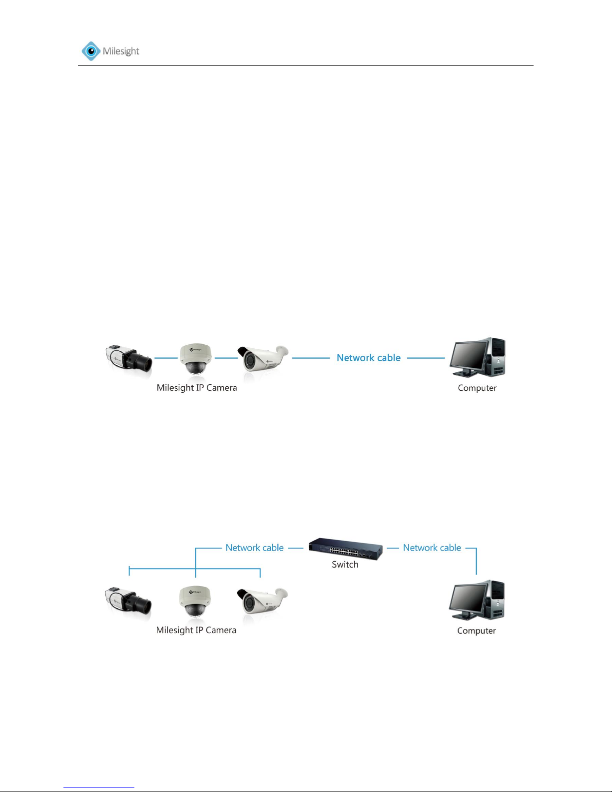
2.1.2 Connect via a Switch or a Router
Refer to the following figure to set network camera over the LAN via the switch or router.
Figure 2-2 Connect via a Switch or a Router
 Loading...