

Page 1

TABLET COMPUTER
DS13
USER’S GUIDE
(Preliminary Version)
BC
○
Page 2

Notice
Copyright© 2018, MilDef Crete Inc. All rights reserved.
No part of this publication may be reproduced and modified without the written permission
of MilDef Crete Inc.
MilDef Crete Inc. reserves the right to make changes in the products or the product
specifications without any prior notice. Customers are advised to contact MilDef Crete Inc.
for updated product information.
MilDef Crete Inc. makes no representations or warranties, either expressed or implied, with
respect to the contents hereof and specifically disclaims any warranties for the correctness
of this book, nor any license grant of MilDef Crete Inc.'s patents or intellectual properties.
MilDef Crete Inc. assumes no liability for customer's loss or damage caused by using this
document.
Trademarks
Trademark Acknowledgments
Intel® is a registered trademark of Intel Corp.
All product and company names are trademarks or registered trademarks of their
respective holders.
I
Page 3

Radiation Exposure Statement
This equipment complies with FCC radiation exposure limits set forth for an uncontrolled
environment. This equipment should be installed and operated with minimum distance
20cm between the radiator & your body.
RF exposure warming
This equipment must be installed and operated in accordance with provided instructions
and antenna(s) used for this transmitter must be installed to provide a separation distance
of at least 20 cm from persons and must not be co-located or operating in conjunction with
any other antenna or transmitter. End-users and installers must be provided with antenna
installation instructions and transmitter operating conditions for satisfying RF exposure
compliance.
Regulatory Information/Disclaimers
Installation and use of this computer must be in strict accordance with the instructions
included in the user documentation provided with the product. Any changes or
modifications (including the antennas) made to this device that are not expressly approved
by the manufacturer may void the user’s authority to operate the equipment.
The manufacturer is not responsible for any radio or television interference caused by
unauthorized modification of this device, or the substitution of the connecting cables and
equipment other than manufacturer specified. It is the responsibility of the user to correct
any interference caused by such unauthorized modification, substitution or attachment.
Manufacturer and its authorized resellers or distributors will assume no liability for any
damage or violation of government regulations arising from failing to comply with these
guidelines.
II
Page 4

Federal Communications Commission regulatory compliance
This device complies with part 15 of the FCC Rules. Operation is subject to the following two
conditions: (1) This device may not cause harmful interference, and (2) this device must accept
any interference received, including interference that may cause undesired operation.
Note:
This equipment has been tested and found to comply with the limits for a class B digital device,
pursuant to part 15 of the FCC Rules. These limits are designed to provide reasonable
protection against harmful interference in a residential installation. This equipment generates,
uses and can radiate radio frequency energy and if not installed and used in accordance with
the instructions, may cause harmful interference to radio communications. However, there is no
guarantee that interference will not occur in a particular installation. If this equipment does
cause harmful interference to radio or television reception, which can be determined by turning
the equipment off and on, the user is encouraged to try to correct the interference by one or
more of the following measures:
Reorient or relocate the receiving antenna.
Increase the separation between the equipment and receiver.
Connect the equipment into an outlet on a circuit different from that to which the receiver is
connected.
Consult the dealer or an experienced radio/TV technician for help.
Important:
Changes or modifications to this product not authorized by MilDef could void the
electromagnetic compatibility (EMC) and wireless compliance and negate your authority to
operate the product.
In order to maintain compliance with FCC regulations, compliant peripheral devices and
shielded cables must be used with this equipment.
III
Page 5

CE Declaration of Conformity
The device is hereby confirmed to comply with the requirements set out in the Council
Directive on the Approximation of the Laws of the Member States relating to
Electromagnetic Compatibility Directive (2014/30/EC) and Complies with the essential
requirements of Article 3 of the R&TTE 2014/53/EC Directive, if used for its intended use
and that the following standards have been applied:
1. Health (Article 3.1(a) of the R&TTE Directive)
Applied Standard(s):
EN 50566
EN 62479:2010
IEC 62209-2:2010
2. Safety (Article 3.1(a) of the R&TTE Directive)
Applied Standard(s):
EN 60950-1:2006 /A11:2009 /A1:2010 /A12:2011 /A2:2013
3. Electromagnetic compatibility (Article 3.1 (b) of the R&TTE Directive)
Applied Standard(s):
EN 301 489-1 V2.1.1/ -17 V3.1.1
4. Radio frequency spectrum usage (Article 3.2 of the R&TTE Directive)
Applied Standard(s):
EN 300 328 V2.1.1
5. Electromagnetic Compatibility Directive (2004/108/EC)
EN 55032: 2012
EN 55022:2010
EN 55024:2010+A1:2015
EN 61000-3-2:2014
EN 61000-3-3:2013
Power Conservation
This computer consumes less power compared to conventional consumer computers. The
power consumption may be further reduced by properly configuring the Power
Management Setup.
It is recommended that the power saving features be enabled even when not running on
battery power. Power Management features can conserve power without degrading system
performance.
IV
Page 6
Power Safety
There are specific power requirements for your computer:
Only use an approved AC adapter designed for this computer.
There is a 3-prong grounded plug for the AC adapter. The 3rd prong is an important
mechanism for ensuring product safety. Please do not neglect the importance of this
mechanism. If you are unable to access a compatible outlet, please hire a qualified
electrician to install a compatible outlet for you.
When unplugging the AC power cord, please make sure to disconnect the cord by
pulling from the plug head instead of pulling from the wire to prevent wire damage.
Make sure the power outlet and any other extension cord(s) you use can support the
total current load of all the connected devices.
Before cleaning the computer, please make sure it is disconnected from any external
power source.
Warning
Before any upgrade procedures, make sure the power is turned off, and all the
cables are disconnected. Also, it is advisable to remove your battery to prevent
your computer from accidentally turning on.
V
Page 7
Battery Precautions
Only use batteries designed for this computer. Using incompatible battery types may
cause explosion, leakage or damage to the computer.
Do not remove the battery from the computer while the computer is powered on.
Do not continuously use a battery that has been dropped, or that appears damaged
(e.g. bent or twisted) in any way. Even if the computer is able to continuously work with
a damaged battery, the circuit damage may occur and possibly cause fire.
Always use the charger designed for this computer to recharge the battery. Incorrect
recharging may cause the battery to explode.
Do not try to repair a battery by yourself. For battery service or replacement, please
contact with your service representatives.
Please dispose damaged battery promptly and carefully. Explosion or leakage may
occur, if the battery is improperly handled or discarded.
Notice:
For safety, charging will stop if the internal temperature of the battery is out of range(<0°C;
>50°C). Please note that charging could have stopped before the ambient temperature
reaching these boundaries because the internal temperature of the battery does not equal
to the ambient temperature.
Battery Disposal & Caution:
The product that you have purchased contains a rechargeable battery. The battery
is recyclable. At the end of its service life, under various state and local laws, it
may be illegal to dispose of this battery into the municipal waste stream. Check
with your local solid waste officials for details in your area for recycling options or
proper disposal. Danger of explosion may possibly occur, if the battery is
incorrectly replaced. Replace only with the same or the equivalent battery
recommended by the manufacturer. Discard the used battery according to the
manufacturer’s instructions.
VI
Page 8

Environmental Information, Material Safety & Recycling
All materials used in the manufacturing of this equipment are recyclable or environmentally
friendly. Please recycle the packing materials in accordance with local regulations at the
end of the product's service life.
Notice:
The equipment may contain insignificant amount of hazardous substances for health
and environment below control level.
To avoid spreading such substances into the eco system and to minimize the pressure
on the natural environment, you are encouraged to reuse or recycle most of the
materials in a safe way after the product’s service life.
For more information on collection, reuse and recycle of materials, please consult local
or regional waste administrations for more information. You can also contact your
dealer for more information on the environmental details of the equipment.
The symbol of the crossed out wheeled bin indicates that the product
(electrical and electronic equipment) should not be placed in municipal
waste. Please check local regulations for disposal of electronic products.
VII
Page 9

TABLE OF CONTENTS
CHAPTER 1 - GETTING STARTED ............................................................... 1
UNPACKING .................................................................................................................. 1
APPEARANCE OVERVIEW ............................................................................................... 2
READY FOR USE ............................................................................................................ 6
CHAPTER2 - OPERATING INFORMATION .................................................. 8
START USING YOUR TABLET COMPUTER ......................................................................... 8
STOP USING YOUR TABLET COMPUTER .......................................................................... 9
WORKING WITH POWER BUTTON (HEATER KIT) ............................................................. 1 0
INSTALLING OPERATING SYSTEM .................................................................................. 11
USING INDICATORS AND KEYPAD .................................................................................. 11
ALIBRATION OF TOUCH SCREEN ................................................................................. 15
C
U
SING MSATA SSD .................................................................................................... 17
USING MICRO SD CARDS ............................................................................................. 18
®
INTEL
OPERATING WIRELESS DEVICES ................................................................................... 19
USING LIGHT SENSOR ................................................................................................. 24
RAPID START TECHNOLOGY ............................................... 錯誤! 尚未定義書籤。
CHAPTER3- MANAGING POWER .............................................................. 25
AC ADAPTER .............................................................................................................. 25
BATTERY .................................................................................................................... 26
BATTERY RECALIBRATION ............................................................................................ 29
ACPI SUPPORT .......................................................................................................... 30
USB FAST CHARGING ................................................................................................. 31
CHAPTER 4 - BIOS SETUP ......................................................................... 32
MAIN MENU ................................................................................................................ 32
A
DVANCED MENU ........................................................................................................ 33
TrustedComputingSub‐Menu...........................................................................................35
SATAConfigurationSub‐Menu...........................................................................................36
Intel(R)RapidStartTechnology Sub‐Menu.......................................................................37
USBConfigurationSub‐Menu............................................................................................38
RFDeviceControlConfigurationSub‐Menu......................................................................39
ECThermalControlSub‐Menu..........................................................................................40
ACINBOOTControlSub‐Menu..........................................................................................40
USBCHARGEControlSub‐Menu........................................................................................42
HIPSET MENU ........................................................................................................... 43
C
PCH‐IOConfigurationSub‐Menu.......................................................................................43
B
OOT MENU ............................................................................................................... 45
SECURITY MENU ......................................................................................................... 46
AVE & EXIT MENU ..................................................................................................... 47
S
CHAPTER 5 – DRIVERS AND APPLICATIONS ......................................... 48
Page 10

CHIPSET ...................................................................................... 錯誤! 尚未定義書籤。
VGA ........................................................................................... 錯誤! 尚未定義書籤。
AUDIO ......................................................................................... 錯誤! 尚未定義書籤。
INTEL ME .................................................................................... 錯誤! 尚未定義書籤。
INTEL RAPID STORAGE TECHNOLOGY ............................................ 錯誤! 尚未定義書籤。
WIRELESS POWER MANAGER ........................................................ 錯誤! 尚未定義書籤。
TURBO BOOST MONITOR .............................................................. 錯誤! 尚未定義書籤。
GIGABIT LAN (OPTION) ................................................................ 錯誤! 尚未定義書籤。
WIFI (OPTION) ............................................................................. 錯誤! 尚未定義書籤。
BLUETOOTH (OPTION) .................................................................. 錯誤! 尚未定義書籤。
GPS (OPTIONAL) ......................................................................... 錯誤! 尚未定義書籤。
TPM (OPTIONAL) ......................................................................... 錯誤! 尚未定義書籤。
USB3.0 (FOR WINDOWS 7) .......................................................... 錯誤! 尚未定義書籤。
LAN (FOR DOCKLITE) ................................................................... 錯誤! 尚未定義書籤。
USB TO COM (FOR DOCKLITE) .................................................... 錯誤! 尚未定義書籤。
CHAPTER 6 – SPECIFICATIONS ................................................................ 49
PLATFORM .................................................................................................................. 49
CPU .......................................................................................................................... 4 9
PCH ........................................................................................... 錯誤! 尚未定義書籤。
MEMORY .................................................................................................................... 49
TOUCH SCREEN .......................................................................................................... 49
STORAGE ................................................................................................................... 49
BUTTONS/FUNCTION KEYS ........................................................................................... 50
AUDIO ........................................................................................................................ 50
I/O PORTS .................................................................................................................. 50
CASE ......................................................................................................................... 51
IMENSIONS AND WEIGHT ............................................................................................ 51
D
POWER ....................................................................................................................... 51
ENVIRONMENTAL, SAFETY & EMC ................................................................................ 52
O
PERATING & STORAGE TEMPERATURE ........................................................................ 52
MATERIALS AND RECYCLING ........................................................................................ 52
CHAPTER 7 – OPTIONAL DEVICES .......................................................... 53
C
OMMUNICATION ......................................................................................................... 53
MEMORY CARD ............................................................................ 錯誤! 尚未定義書籤。
SECURITY ................................................................................................................... 53
AMG SENSOR MODULE ............................................................................................... 53
MIL. FISCHER CONNECTOR .......................................................................................... 53
EXTERNAL VEHICLE ADAPTER ...................................................................................... 53
EXTERNAL USB KEYBOARD ......................................................................................... 54
INI KEYBOARD KBD .................................................................................................. 55
M
Page 11

CHAPTER 8 – MAINTENANCE AND SERVICE .......................................... 56
CLEANING ................................................................................................................... 56
TROUBLESHOOTING ..................................................................................................... 56
RMA SERVICE ............................................................................................................ 57
Page 12
GettingStarted
Chapter 1 - Getting Started
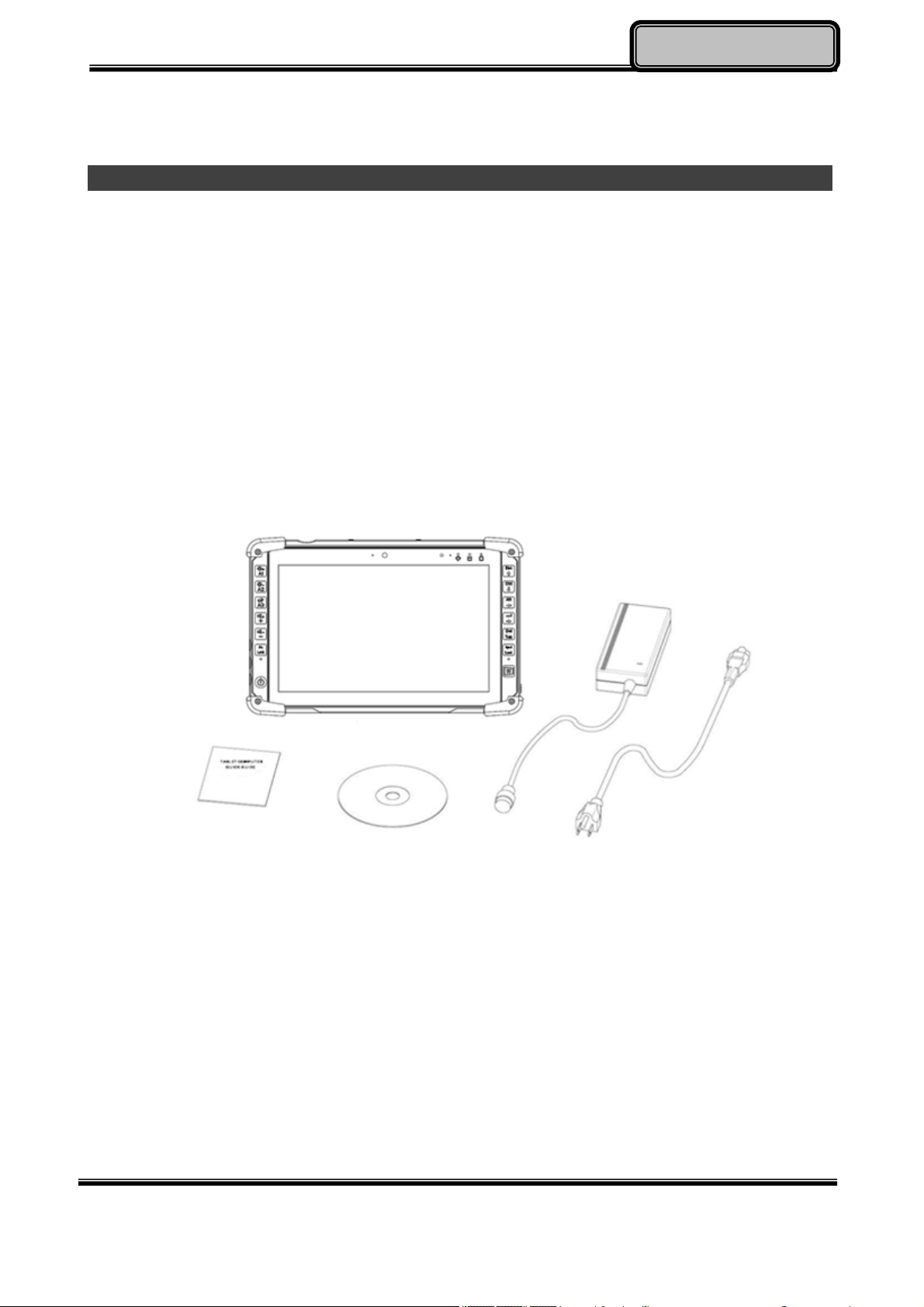
Unpacking
The following components come with your computer. If anything is missing or damaged,
please notify the dealer immediately.
Computer unit
AC Adapter
AC Power Cord
Utility DVD
Quick Guide
Chapter One - 1
Page 13
GettingStarted
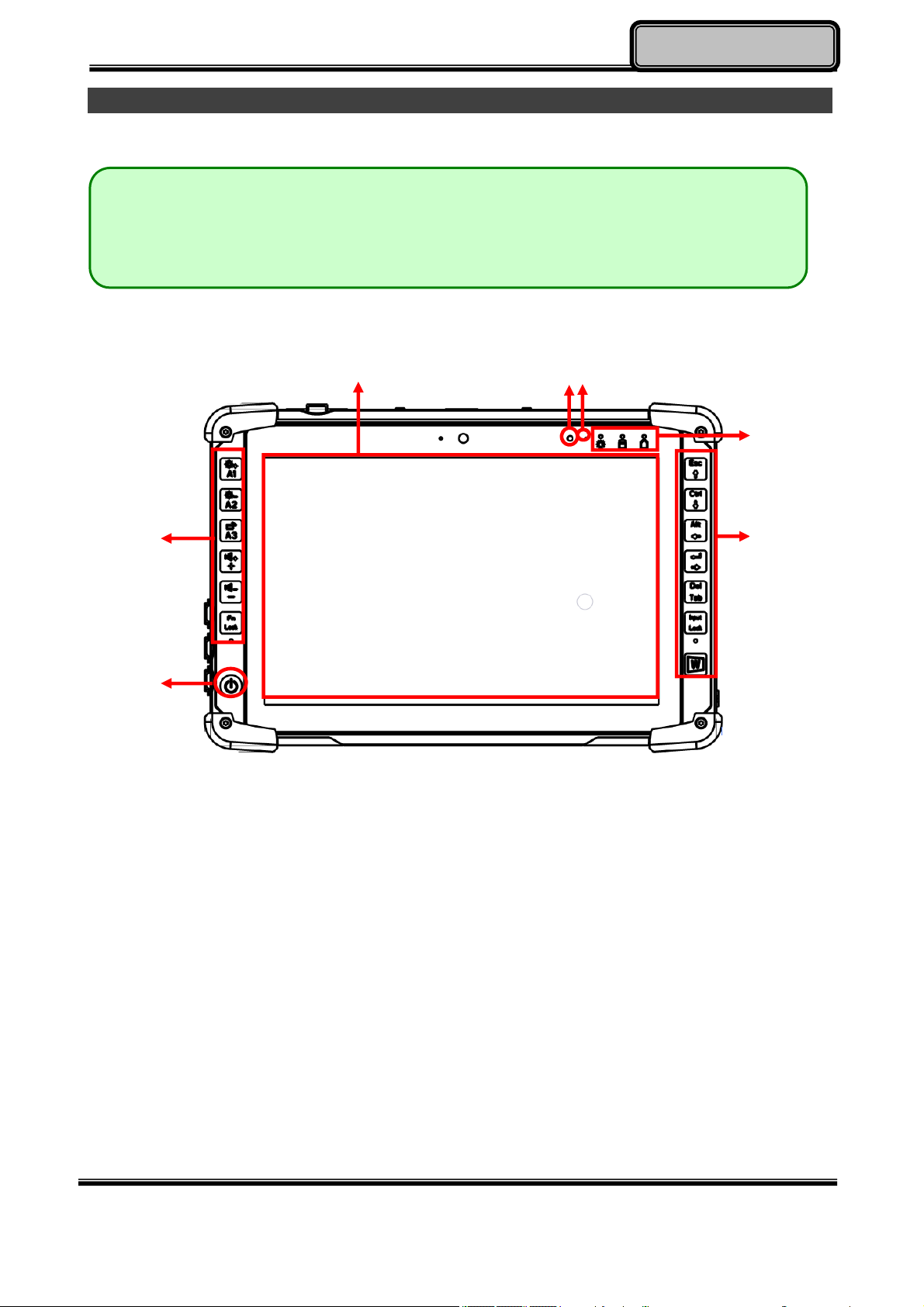
Appearance Overview
Note:
The following illustrations show the tablet mounted on optional devices, which
may not appear on your devices.
Front
6
5
3
2
1
1. Power Button
2. Function keys & Input Lock Key
3. LED Indicators
4. Touch Screen
5. Light sensor
6. Embedded digital Mic
2
Chapter One - 2
Page 14
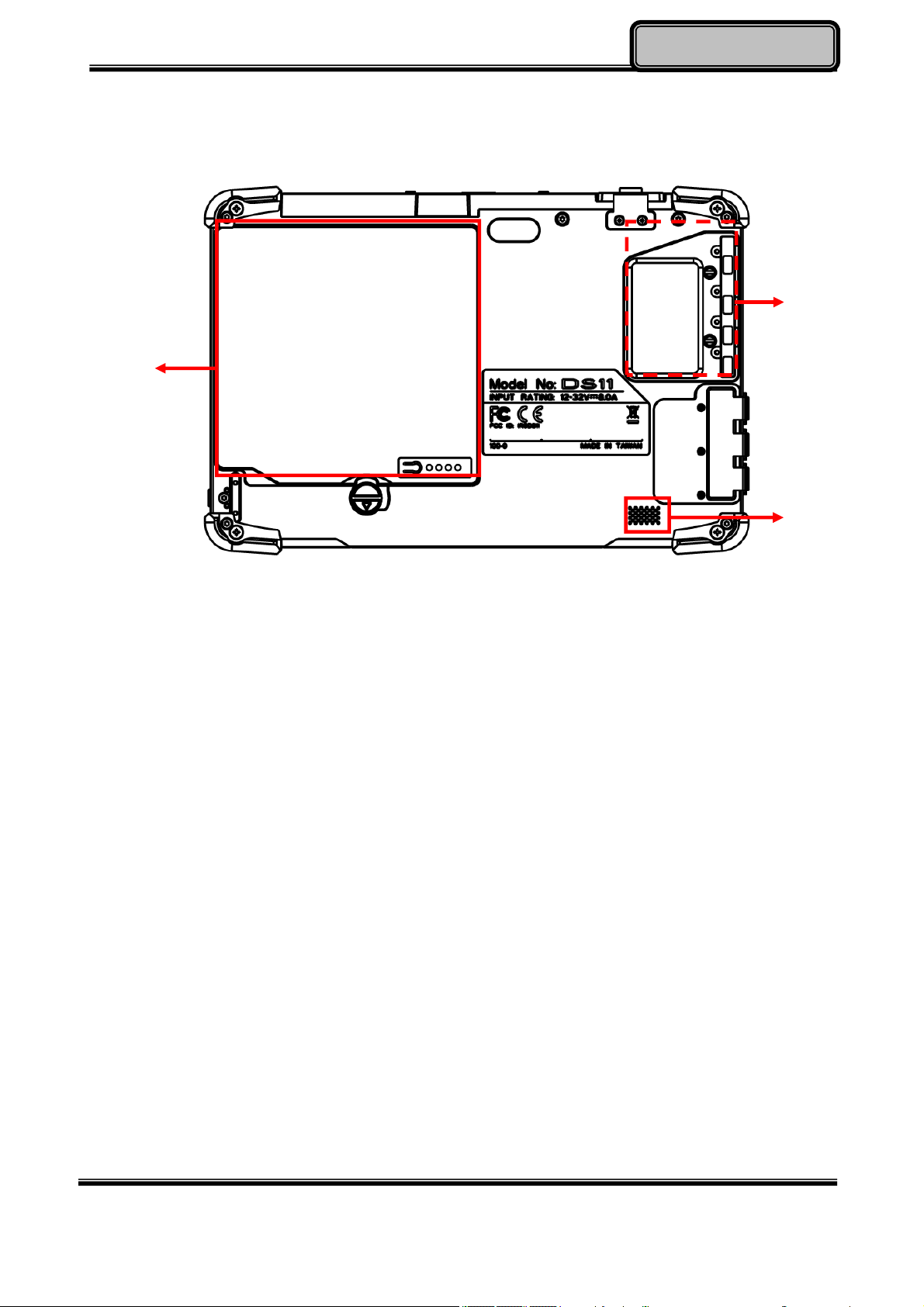
Rear
GettingStarted
2
1
1. Removable battery pack
2. Removable mSATA SSD
3.
HD Audio & mono Speaker
3
Chapter One - 3
Page 15
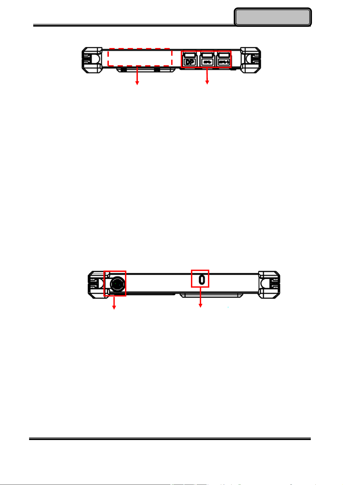
Left
GettingStarted
1
1. Optional Fischer I/O (From left to right X4, X3, X2, X1)
Choose 1~4 out of 6 as below:
- USB 2.0 x1
- COM x 2 (RS232 x 2 or RS232 x1/RS422 x 1)
- 2nd GLAN x1
- Audio x1
- Sealed Headset (Headphone out/Mic-in Combo) x1
2. Standard: Mini DisplayPort x 1/USB3.1 x 2
Optional: Mini DisplayPort x 1/USB3.1 x 1/ GLAN x 1
Right
2
1
1. DC-In 12~32V
- Default: Fischer 3-pin connector
2. Kensington cable lock slot
2
Chapter One - 4
Page 16
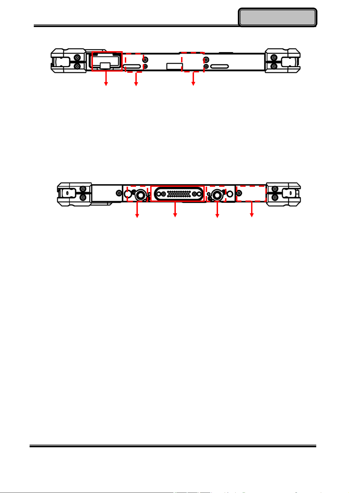
GettingStarted
Top
1
1. Micro SD Card Slot
2. Optional Built-in Wi-Fi Antenna
3. Optional Built-in GPS Antenna
Bottom
2
3
3
1
1. Docklite connector
2. Optional Built-in Wi-Fi/BT Antenna
3. Ext. Antenna signal
3
2
Chapter One - 5
Page 17
GettingStarted
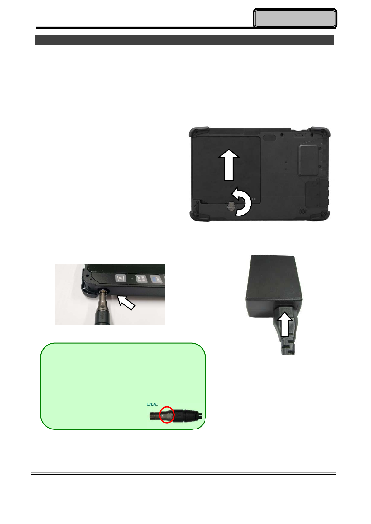
Ready for Use
After taking a quick look at your tablet computer, the following illustrations will get you ready
for using it.
1. Mounting the Battery
A. Mount the battery into the battery bay.
B. Turn the battery lock counter-clockwise
and lock firmly with a flat-head
screwdriver or a coin.
2. Connecting the AC Adapter
A
B
A. Insert the DC Jack firmly.
Note:
When unplugging the Fischer conn. from
the DC Jack, please always hold on the
outer sleeve of the plug, as the image
shows, to unlock and pull out:
Chapter One - 6
B. Plug the AC cord into the AC
adapter.
C. Plug the AC power plug into
an electrical outlet.
Page 18
GettingStarted
3. Turning ON the Power
A. Make sure the battery is securely mounted. Connect all power cords properly.
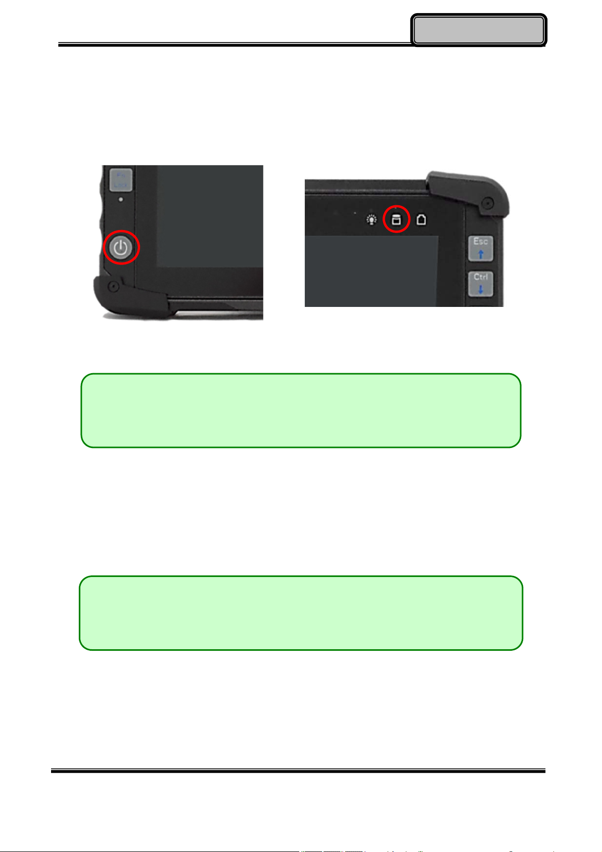
B. Turn on the power of your tablet computer by pressing and holding the Power Button
(approx. 2 seconds) until the SSD/ Heater Indicator lights on (Color: orange).
Note:
The computer is able to turn ON without any battery mounted once all the
power cords are connected.
4. Turning Off the Power
Directly tap “Shut down” from your OS to turn OFF the power of your tablet computer. If
your tablet computer stops responding, press and hold the power button for 4~5 seconds to
“Force Shut down” your tablet computer.
Note:
Directly turning off the power of your tablet computer by “Force Shut
down” will cause all unsaved data to be lost and is not recommended.
Chapter One - 7
Page 19

OperatingInformation
Chapter2 - Operating Information
Start Using Your Tablet Computer
Always turn on your tablet computer by using the power button. This is the standard
operating procedure to start using your tablet computer. After turning on the power of your
tablet computer, it will start with the Operating System (OS) installed.
Boot Up
When you turn on the power, your computer will start to load the OS into the system
memory. This start-up procedure is called “boot up”.
Power On Self-Test (POST)
Each time your computer is turned on, the BIOS will automatically perform a self-test of
CPU, memory, hardware devices, and so on.
Chapter Two - 8
Page 20

OperatingInformation
Stop Using Your Tablet Computer
Each time when you finish working with your tablet computer, there are several ways to stop
your tablet computer from operating.
Shut down
Directly click “Shut down” from your OS to turn OFF the power of your computer. Before
shutting down, please do remember to save unfinished works and close your applications to
prevent your SSD from suffering possible data loss or damage. “Shut down” will turn OFF
power of your computer. If you want to start your computer again, you need to turn it ON
again by pressing the power button.
Sleep
Under “Sleep” mode, the system will temporarily save your work into the computer’s RAM.
If you want to start your computer again, please press the power button to resume. Under
Windows 8, you can enter this mode by directly clicking:
Move your cursor to the upper-right or lower-right corner of the screen, and then
click “Settings” => Click “Power” => Click “Sleep”.
Hibernate
Under “Hibernate” mode, the system will save your work into SSD. If you want to start your
computer again, you need to press and hold the power button (approx. 2 sec.) until the
SSD/Heater indicator lights on. Under Windows 8, you can enter “Hibernate” mode by
directly clicking:
Move your curse to the upper-right or lower-right corner of the screen, and then click
“Settings” => Click “Power” => Click “Hibernate”.
Force Shut Down
In the event that your tablet computer hangs or stops responding, you can perform a force
shut down by pressing and holding the power button for 4~5 seconds. Please note that any
unsaved work or data will be lost this way.
Chapter Two - 9
Page 21

OperatingInformation
Working with Power Button (Heater Kit)
DS11 M-model is equipped with a heater kit to enable work under low temperature. The
heater will heat up the LCD to the temperature for booting up the system. Also, the heater
will constantly monitor LCD temperature. Once the temperature becomes lower, the heater
will heat up again to maintain the temperature for operation.
Note:
When ambient temperature is under -15 °C (the default setting for your tablet
computer), the system may not boot up immediately. System will beep with Heater
LED light flashing orange to indicate that the heater is in operation. After 3~10 minutes
(depending on the ambient temperature), the system will boot up automatically.
In emergency situations, you can skip the heating process by pressing and holding the
power button for 9~11 seconds then release. The speaker will beep with a special
sound to signify that the heating process has been skipped (Please note that not all
devices are guaranteed to work properly in this case).
Press the power button again during the heating process will shut down the computer.
The following is a list of functions associated with your tablet computer’s power button:
1. Press and hold for 9 ~ 11 seconds:
The system will skip heating process and force boot up.
2. Press and hold for 5 ~ 8 seconds:
Enable/Disable the sound of Heater.
3. Press and hold the power button for 4 seconds under OS:
Shut down the system.
4. Press the power button for functions including:
a. Power on the system.
b. Force Shut Down.
c. Sleep/Hibernate (Dependent on OS settings).
Chapter Two - 10
Page 22
OperatingInformation
Installing Operating System
Your computer is designed to operate with Microsoft Windows 7 or Windows 8 32 / 64-bit
Operating System. Please connect your computer with an external USB-interface drive to
start the OS installation.
Note:
A USB hub may be required during installation to connect with an external
USB-interface ODD, as the System USB port may not supply enough power.
Please connect your USB hub with extra power supply to complete the
installation.
Indicators and Function keys
LED Indicators
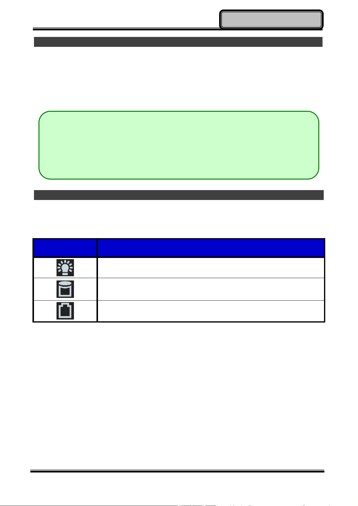
LED Indicator Description
Power/ S3 Indicator:
Green/ Flashing Green
mSATA SSD/ Heater Indicator:
Green/ Orange
Charger/ Battery Low Indicator:
Orange/ Flashing Orange
Chapter Two - 11
Page 23
OperatingInformation
Function Keys
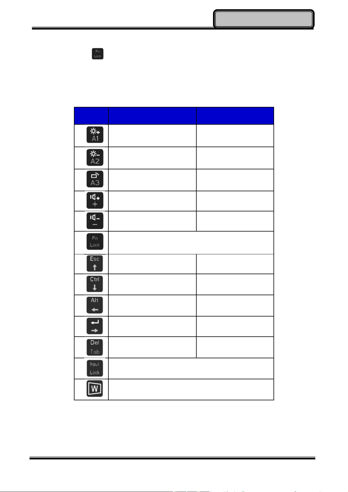
Function Lock key is used to switch function of the other buttons. Press the function
Lock key to switch between 2 layers. The indicator under the function Lock key will light up
if the other buttons are in 2nd layer and it will be turned off if in 1st Layer.
Button 1st Layer 2nd Layer
Brightness Up
Brightness Down
Rotation Lock
Volume Up +
Volume Down -
Function Lock
Esc
Ctrl
(User settable)
(User settable)
(User settable)
A1
A2
A3
↑
↓
Alt
Enter
Del Tab
Input Lock
Windows Key
←
→
Chapter Two - 12
Page 24
OperatingInformation
Setting Function for Buttons A1~A3
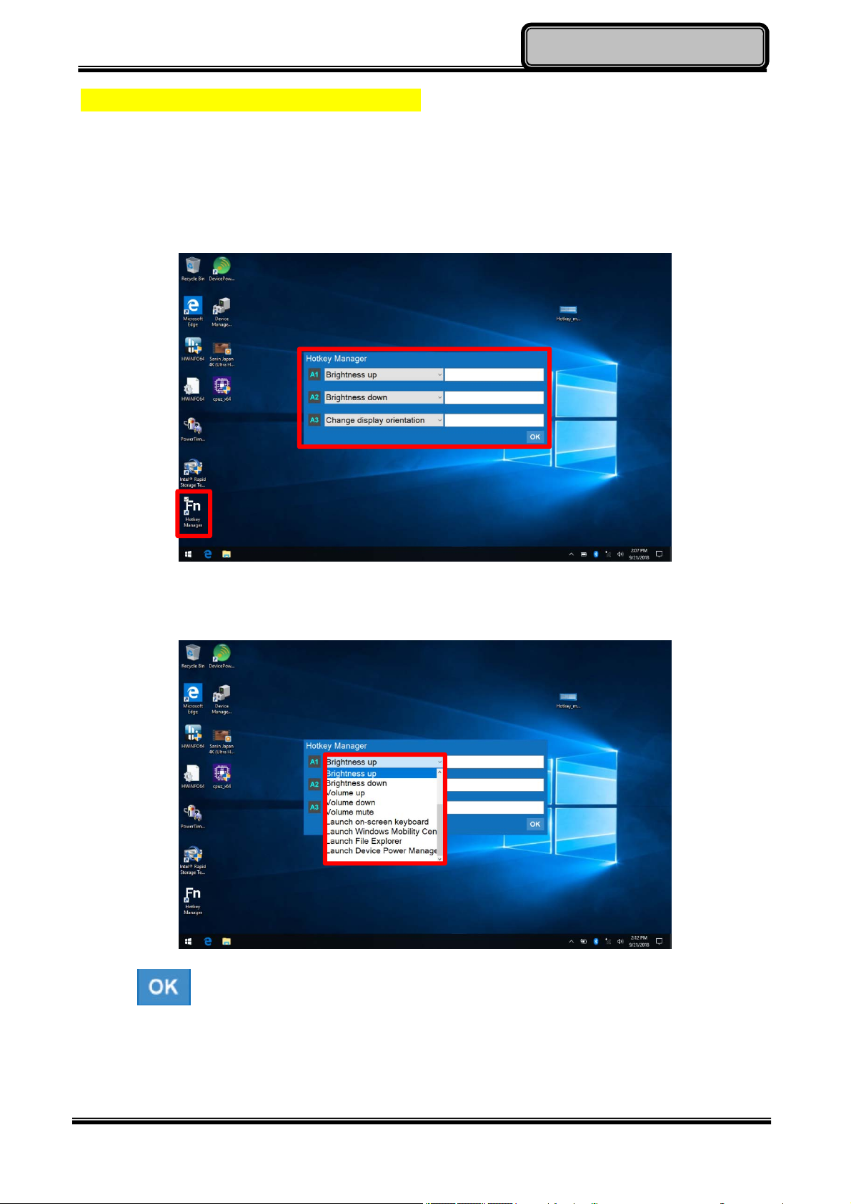
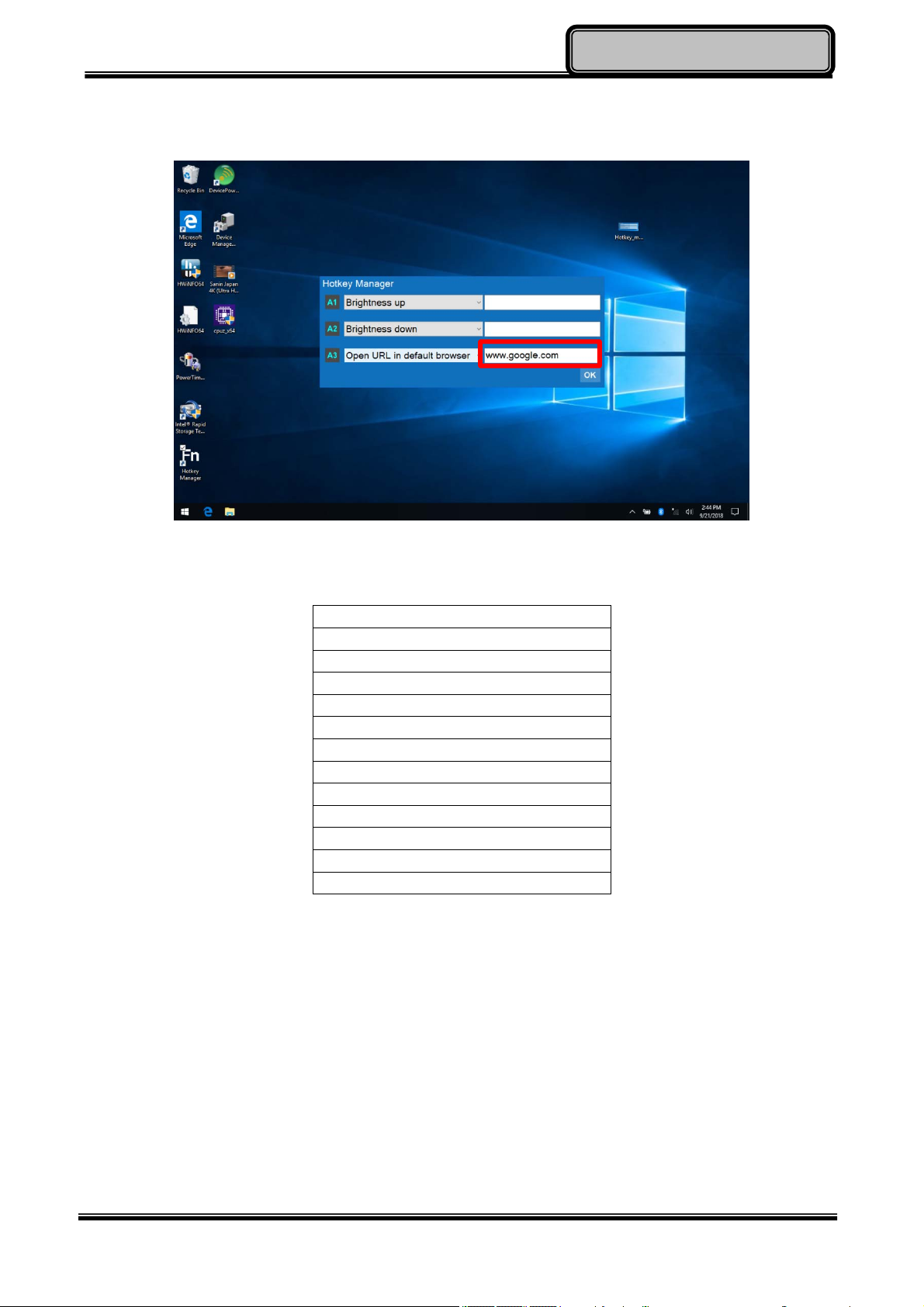
Hotkey Manager is an app which could be used to quickly set up and change between
multiple functions for A1, A2 and A3. Please follow these procedure to use it.
1. Operate the Hotkey Manager then a menu will show up.
2. Scroll down to select function for each key.
3. Click and the setting will be saved automatically.
Chapter Two - 13
Page 25
OperatingInformation
4. The blank could be filled with related parameter according to the selected function.
E.g. Fill in the address to use the function “Open URL in default browser”.
Available Function Items List
None
Open/ Execute a selected file
Open URL in default browser
Change display output
Brightness up
Brightness down
Volume up
Volume down
Volume mute
Launch on-screen keyboard
Launch Windows Mobility Center
Launch File Explorer
Launcher Device Power Manager
Input Lock key
To prevent from unexpected input by buttons and touch screen, you can press Input Lock
key. When Input Lock function is on, the input from devices including buttons and touch
screen will be locked. To cancel the input lock function, just press the Input Lock key again
and the indicator will be turned off.
Chapter Two - 14
Page 26
OperatingInformation
Calibration of Touch Screen
Calibration
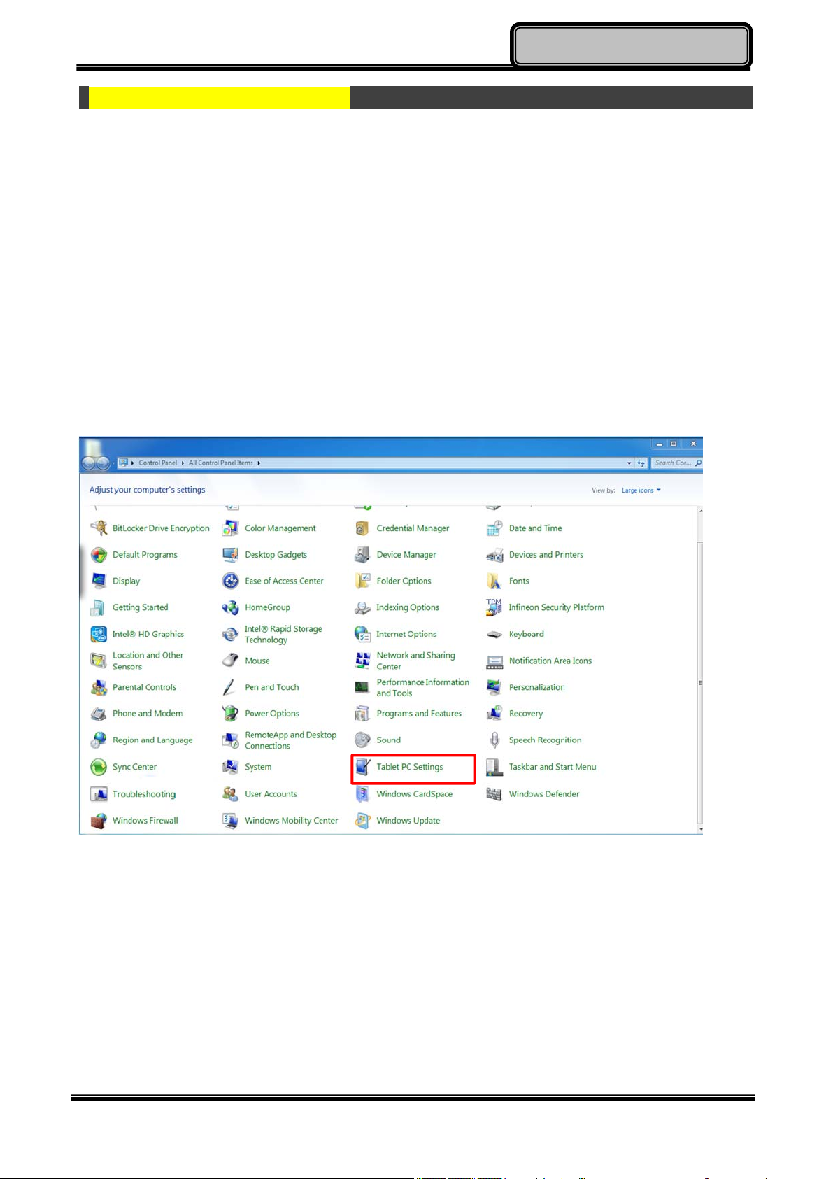
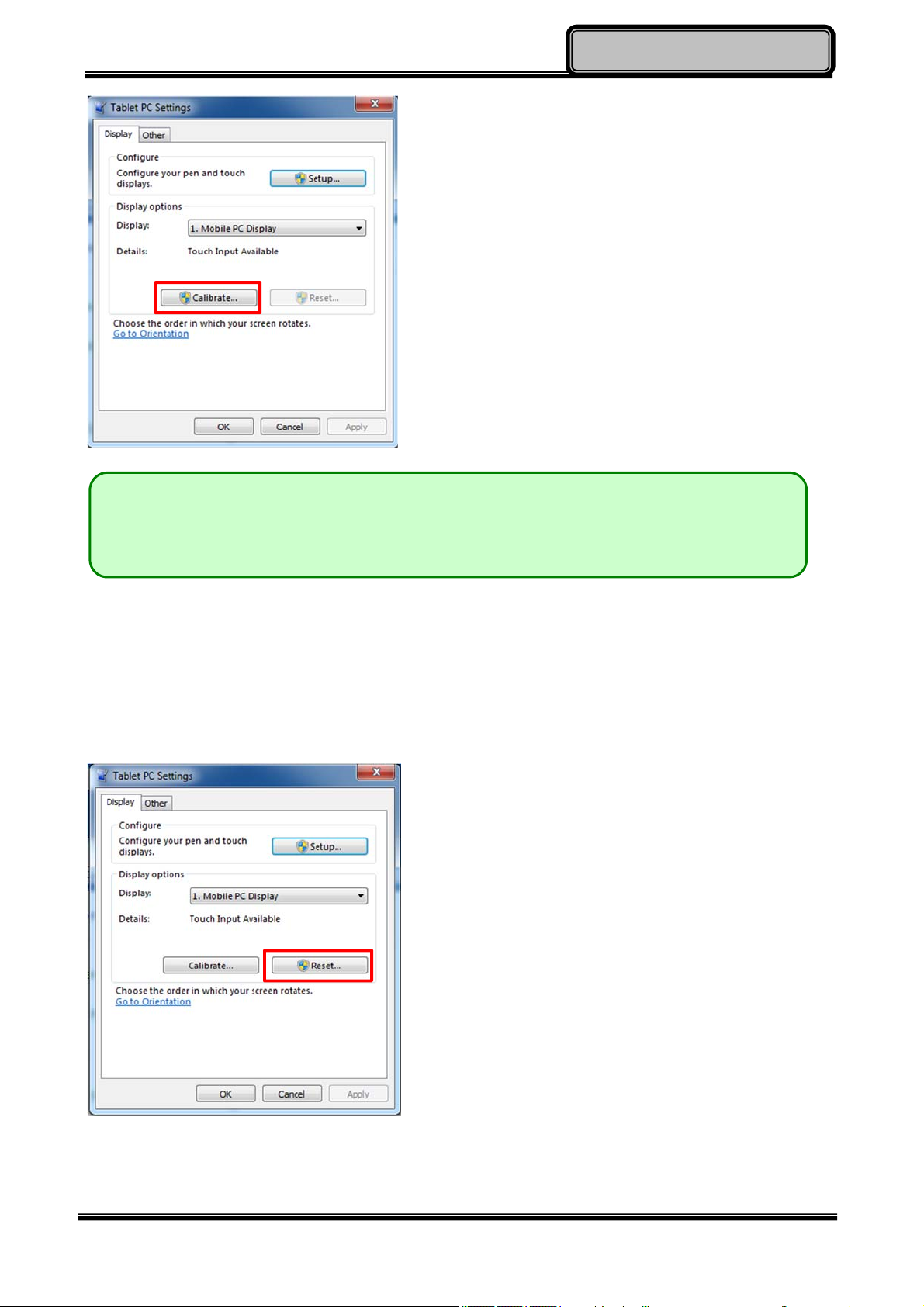
If you find that the touch screen doesn’t respond accurately, you may try to fix the problem
with the embodied calibration function. However, if the touchscreen type of your tablet is
capacitive
inaccuracy problem worse.
To calibrate your touch screen, please follow the instruction below.
Control panelTablet PC SettingsCalibrate
rather than
resistive
, the calibration might cause interference and make the
Chapter Two - 15
Page 27
OperatingInformation
Note:
If you are unaware of the type of your touch screen, calibration should be
avoided.
Reset
In case the calibration is operated accidently and results in interference and inaccuracy,
you can choose reset in the same page.
Chapter Two - 16
Page 28
OperatingInformation
Using mSATA SSD
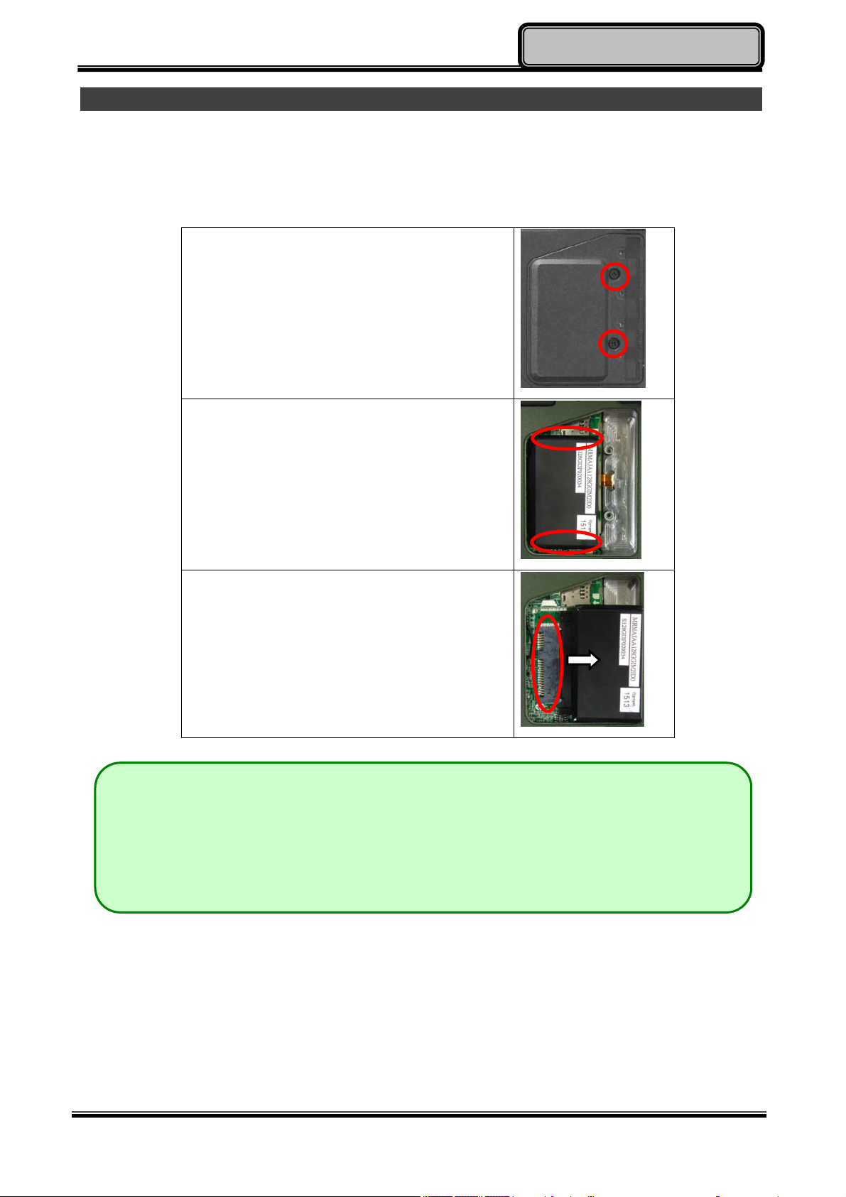
Your tablet is equipped with mSATA SSD for data storage. The mSATA SSD is removable
for convenience. It can ONLY be removed while power is OFF. To remove the mSATA SSD
module, please follow the steps below:
1. Loosen the screws on Back Door
Cover, and then remove the cover.
2. Hold the two ends of the mSATA SSD
module.
3. Remove the mSATA SSD module from
the connector.
Note:
Do not expose mSATA SSD directly to high temperature, high humidity, and
other hazardous environment. NEVER try to disassemble the module. Static
discharge may destroy your device and data.
Chapter Two - 17
Page 29
OperatingInformation
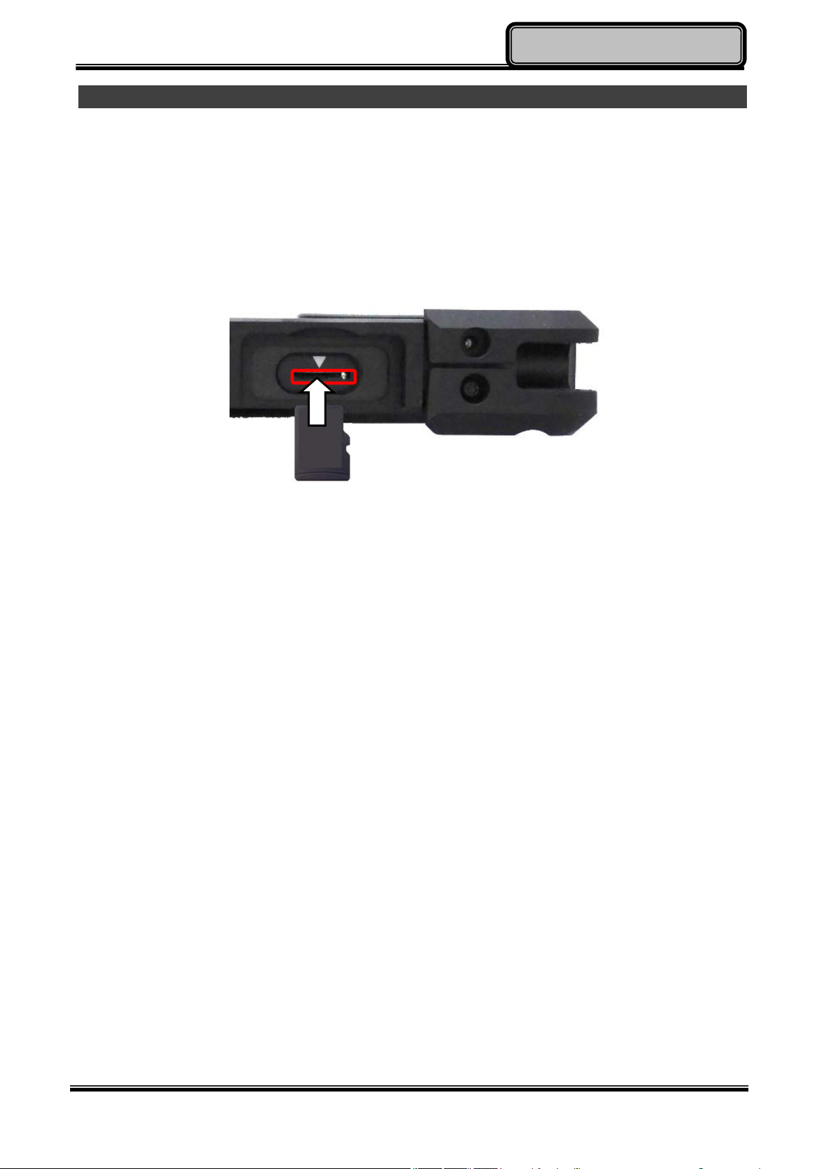
Using micro SD Cards
Your tablet computer is equipped with a micro SD card slot. The slot supports SDHC,
SDXC, UHS-1 type micro SD cards. To avoid damages caused by misinsertion, please
insert your micro SD card into the card slot properly with the connectors facing down, as
shown below.
Chapter Two - 18
Page 30
OperatingInformation
Operating Wireless Devices
For your ease of operations, you can turn on/off your wireless devices through the
proprietary software application - “Device Power Manager”.
Note:
Depending on the configuration of your tablet computer, your Device Power
Manager menu may appear differently from the screenshots provided in this
section.
When you adjust User Account Control (UAC), a security feature in Windows,
the setting value of Device Power Manager will be affected. So, once there is
any adjustment on UAC, please uninstall Device Power Manager and
reinstall it again.
Bluetooth (Option)
The Bluetooth module provides your tablet computer with a short-range wireless
communication protocol to connect with other compatible devices via the pre-installed
embedded antenna. To activate your Bluetooth functions, please follow the instructions
below.
1. Driver & Application Installation
a. Install the Bluetooth driver first. Read from the Utility DVD and find the directory
listed in the readme file to finish installation.
b. Install the Device Power Manager application. Read from the Utility DVD and find
the directory listed in the readme file to finish installation.
Chapter Two - 19
Page 31
OperatingInformation
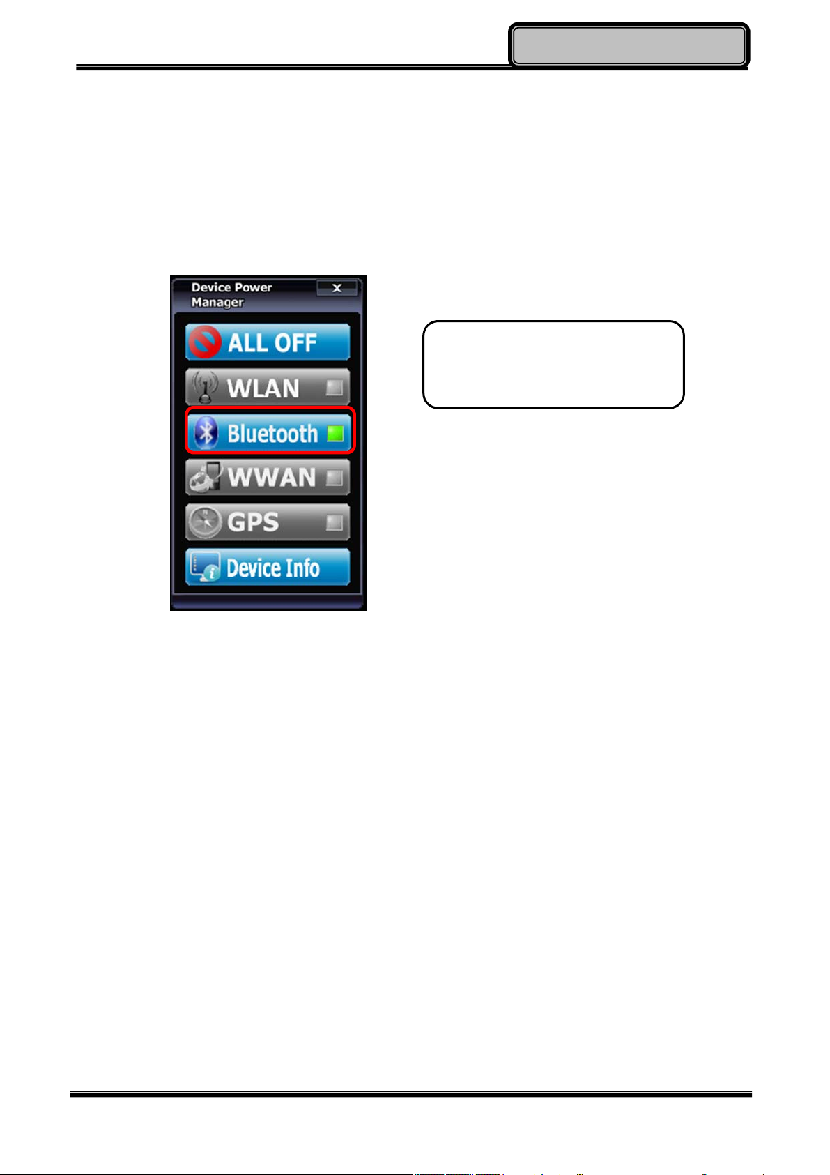
2. Launch the Device Power Manager
After launching the utility, please tap “Bluetooth” to enable the Bluetooth function (tap
again to disable). Once the Bluetooth function starts up, the wireless LED indicator
(color blue) will turn on and the Bluetooth icon will show up in the operating system
accordingly.
Tap “Bluetooth” to enable the
Bluetooth function (tap again to
disable).
Once the Bluetooth function starts up, the wireless device LED indicator will turn on (color
blue) and the Bluetooth icon will appear in the OS accordingly.
Chapter Two - 20
Page 32
OperatingInformation
Wireless LAN (Option)
Wireless LAN is an optional wireless communication module for your tablet computer. An
embedded antenna will be pre-installed in your tablet computer to access the internet
wirelessly. To activate your Wireless LAN function, please follow the illustrations below:
1. Driver & Application Installation
a. Install the Chipset Driver first. Read from the Utility DVD and find the directory
listed in the readme file to finish installation.
b. Then, install the Device Power Manager application. Read from the Utility DVD
and find the directory listed in the readme file to finish installation.
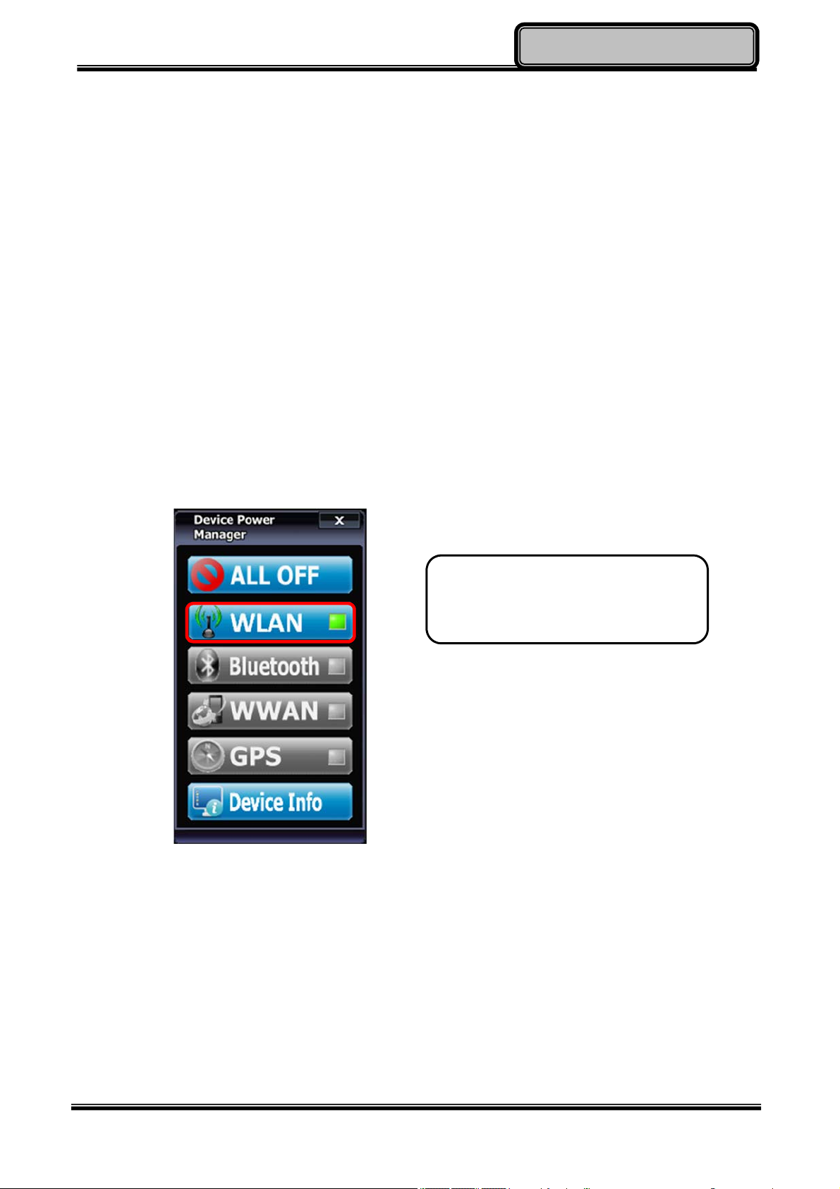
2. Launch the Device Power Manager
After launching the utility, please tap “Wireless LAN” for enabling the Wireless LAN
function (tap again to disable).
Tap “Wireless LAN” to enable the
Wireless LAN function (tap again
to disable).
Once the Wireless LAN function starts up, the wireless device LED indicator will turn on
(color blue) and the Wireless LAN icon will appear in the OS accordingly.
Chapter Two - 21
Page 33
OperatingInformation
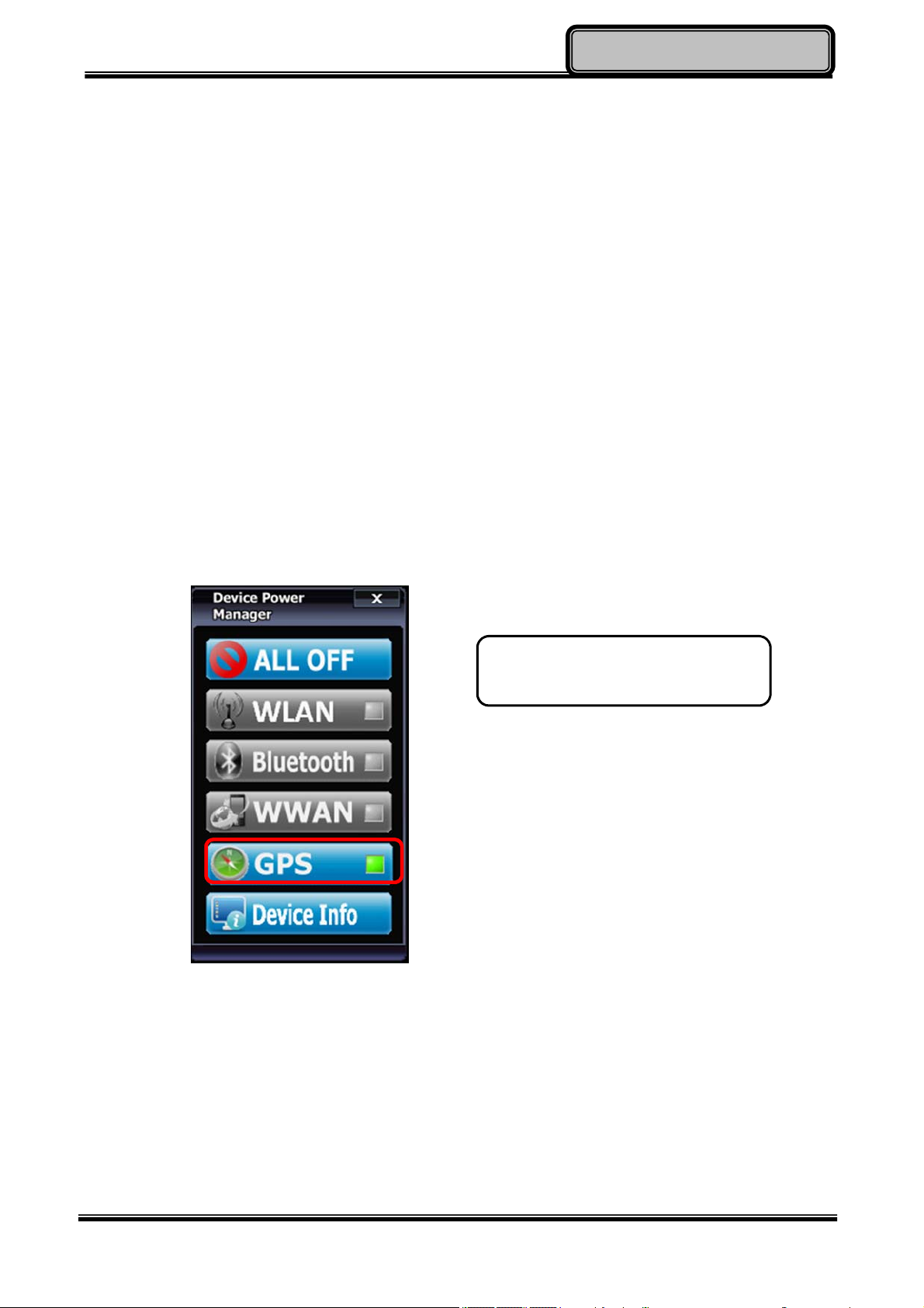
GPS (Option)
GPS is an optional module for your tablet computer. This GPS module supports both GPS
and GLONASS systems. An embedded antenna is pre-installed in your tablet computer to
support the functions of your GPS and GLONASS.
1. Driver & Application Installation
a. Install the Device Power Manager application:
Read from the Utility DVD and find the directory listed in the readme file to finish
installation.
b. Install the GPS driver:
GPS (Driver): Read from the Utility DVD and find the directory listed in the readme
file to finish installation.
Tap “GPS” to enable the GPS
function (tap again to disable).
2. Navigation & Mapping Software Installation
Please install your 3rd party navigation and mapping software after installing your GPS
driver. Refer to your navigation and mapping software manual for installation and
procedures on application setup and access.
Once the GPS function starts up, the wireless device LED indicator will turn on (color blue).
Chapter Two - 22
Page 34
OperatingInformation
Note:
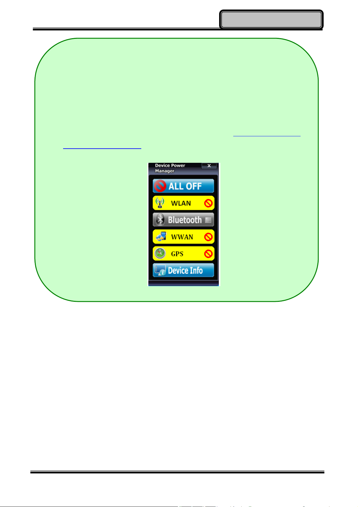
Wireless devices can be turned ON/OFF through BIOS. Once a device is
turned off through BIOS, its button on the Device Power Manager will be
colored in yellow and with a prohibition marker. For example, the following
illustration shows that WLAN and GPS devices are disabled through BIOS.
To turn on, please enter into BIOS and enable the functions. For more
information on BIOS setting, please refer to RF Device Control
Configuration Sub-Menu section.
Chapter Two - 23
Page 35
OperatingInformation
Using Light Sensor
Light sensor can detect the ambient light and adjust the brightness of your tablet computer,
hence improving user experience and power savings. Please enable the function from the
setting below:
Chapter Two - 24
Page 36

r
ManagingPowe
Chapter3- Managing Power
AC Adapter
The AC adapter performs two functions:
- It powers the computer from an external AC source.
-
- It charges the computer battery.
The adapter automatically detects the AC line voltage (110V or 220V) and adjusts
accordingly.
The following are recommended when using the AC adapter:
- Use a properly grounded AC outlet.
- Use one AC outlet exclusively for the computer. Having other appliances on the same
line may cause interference.
- Use a power strip with built-in surge protection.
Connect the AC adapter:
- Plug the AC cord to the adapter.
- Plug the other end of the AC cord into the wall outlet. Make sure the green LED on the
adapter turns on.
- Attach the DC plug into the power jack of the computer.
AC Adapter Indicator
The green LED indicates that AC power is ready.
Chapter Three - 25
Page 37

r
ManagingPowe
Battery
The computer will automatically switch to battery when the external power source (AC
adapter or optional vehicle adapter) is disconnected.
Battery Power Saving Tips
The computer comes with an intelligent power-saving feature. You may extend the battery
life by:
- Setup power saving functions in Operating System Power Management options (e.g.
Windows Power Options).
- Lower the intensity of the display by brightness control.
- Turn the computer into standby (by Sleep or Power button) when it is temporarily not in
use.
- Shut down the computer when it will not be in use for longer period of time.
Battery Low
When the battery is nearly exhausted, the computer gives the following “Battery Low”
warnings:
- Windows battery low warning.
- The power LED flashes.
Once the “Battery Low” warning occurs, please:
- Save and close the files you are currently working on then shut down the computer.
- Plug in AC or vehicle adapter to recharge the battery.
Charging the Battery
Plug in the AC adapter to start the battery charging. If the battery is already full, the sense
circuitry will stop high current charge within several minutes.
Charge indicator turns ON when the battery is charging and turns OFF when the battery
charging is completed.
Chapter Three - 26
Page 38
ManagingPowe
r
Battery Level
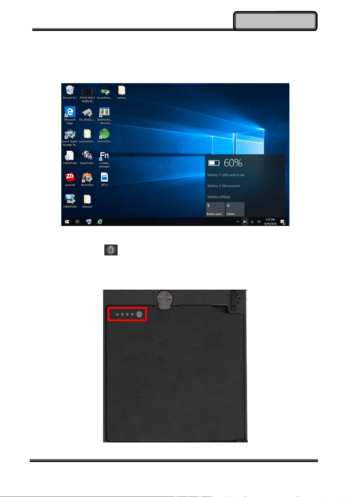
You may check battery status from Operating System. In Windows, you can click the
power/battery icon to reveal the battery gauge window. The following is the illustration of
Battery Gauge in Windows OS.
An alternative way to check the battery level is by viewing the battery gauge on the battery
pack. By pressing the button, indicators will be on. There are four indicators, and the
more indicators are on, the more power remains in the battery. In other words, if the
capacity of the battery pack is full, all indicators will be on, and if the capacity is nearly
drained, no indicator will be on.
Chapter Three - 27
Page 39

ManagingPowe
r
Note:
Battery characteristic varies depending on factors such as ambient
temperature, charging method, load current, aging, etc. For example, the
chemicals of the battery are more inactive at low temperature, thus decreases
the output power.
The battery gauge should only be used as a reference. Please do not expect
it to show the exact amount of the power remaining. There is no memory
effect on Lithium Ion battery cells. However, discharge the battery to nearly
empty every month will help calibrating the internal gauge.
Chapter Three - 28
Page 40
r
ManagingPowe
Battery Recalibration
Battery recalibration allows users to maintain the battery in a healthy condition. To perform
battery recalibration, please follow the steps as below:
1. Update BIOS & EC to the latest version.
2. Insert the battery to the computer, and connect it to AC adapter.
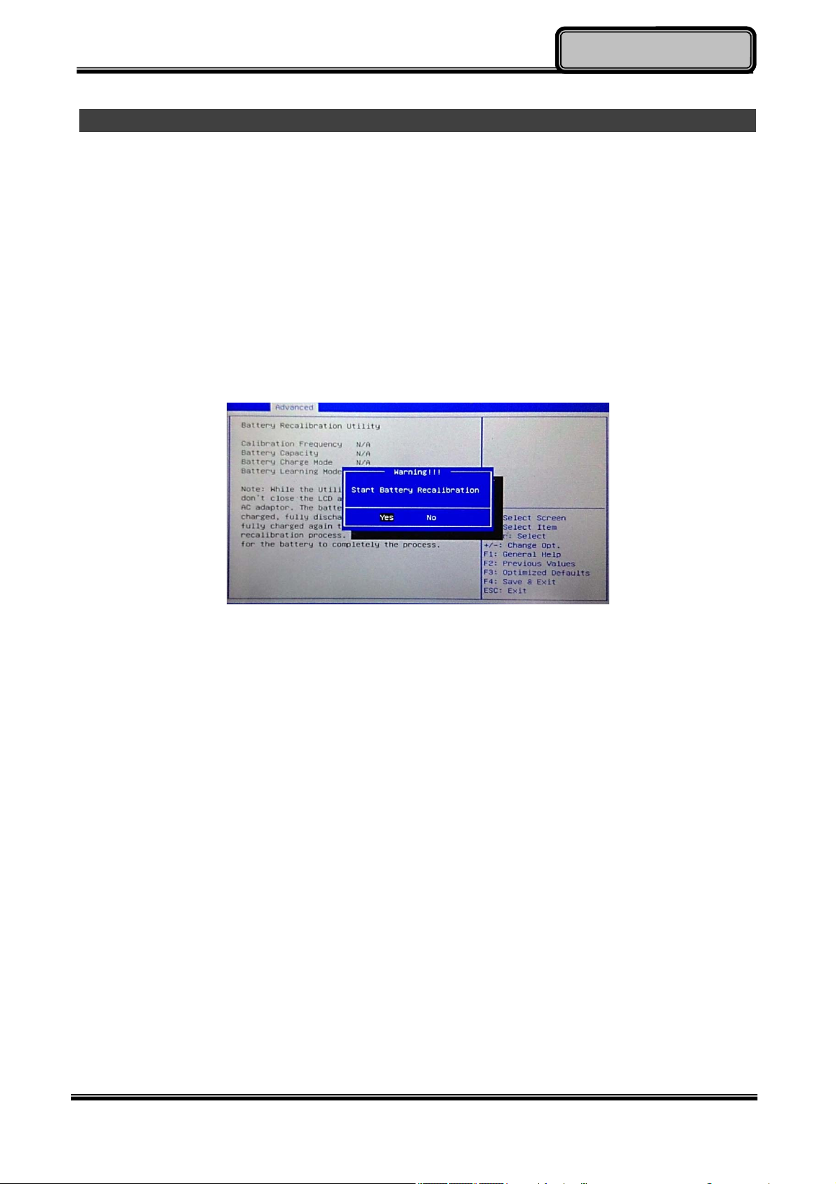
3. Enter the BIOS => Choose “Advanced menu” => Choose “Battery Recalibration” =>
Press “Enter”.
4. When the “Start Battery Recalibration” pop-up appears, press “Yes” to continue. (Before
you run the battery calibration, please make sure that the battery level must be LOWER
than 95% ; otherwise, the calibration cannot work.)
5. The recalibration is now processing. You can see the following recalibration status on the
screen:
- Calibration Frequency: How many times the calibration is processed
- Battery Capacity: Current battery capacity
- Battery Charge Mode: Charge/Discharge
- Battery Learning Mode: Normal (charge)/Learn (discharge)
6. A pop-up appears when the calibration is completed. Then click “OK”.
7. Press “Yes” to reboot the computer when “Reset Without Saving” pop-up appears.
Chapter Three - 29
Page 41
r
ManagingPowe
Note:
Do not turn off the LCD and do not remove AC adapter during the calibration.
One cycle of recalibration process indicates “Charge to Full => Start Learn Mode
=> Discharge => Complete Learn Mode => Charge to Full”. It will take approx.
eight hours for a cycle.
It requires five cycles to complete the battery recalibration. Then the recalibration
will stop automatically.
If you want to terminate the calibrating, simply shut down the computer by
pressing Power Button or just press "CTRL+ALT+DEL" to restart.
ACPI Support
Your computer supports ACPI (Advanced Configuration and Power Interface) for power
management. With ACPI and an ACPI-compliant operating system (such as Microsoft
Windows), this feature will allow you to reduce the power consumption and conserve
energy. By supporting ACPI, the AC adapter LED and the Power indicator LED will show in
different ways. The followings are detailed descriptions of LED indicators and their
meanings:
Sleep:
AC adapter LED is ON (while connecting with power)
Power LED indicator is flashing Green; other LED indicators are OFF
Hibernate:
AC adapter LED is ON (while connecting with power)
Power LED indicator is OFF; other LED indicators are OFF
Shut down:
AC adapter LED is ON (while connecting with power)
Power LED indicator is OFF; other LED indicators are OFF
Chapter Three - 30
Page 42
r
ManagingPowe
USB Fast Charging
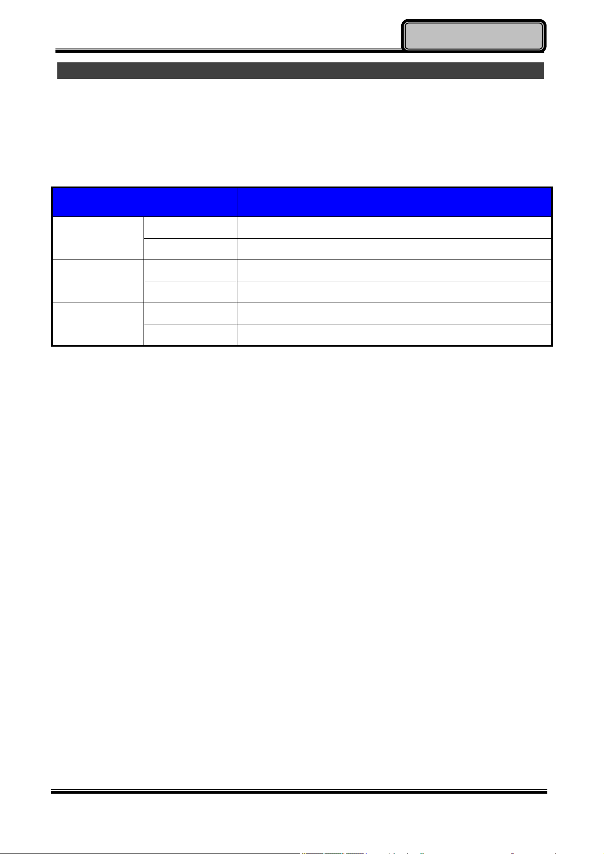
Your tablet supports USB fast charging feature, enabling to quickly charge your
fast-charging compatible devices. But note, fast charging is not supported in every power
mode. The following table shows details for USB Charging information:
Mode USB 3.0 Charging Features
AC Fast charging supports
Power off
Battery No charging
AC Normal charging
Power on
Battery Normal charging
AC Fast charging supports
S3
Battery Fast charging supports
Chapter Three - 31
Page 43
Optional Devices
BIOSSetup
Chapter 4 - BIOS Setup
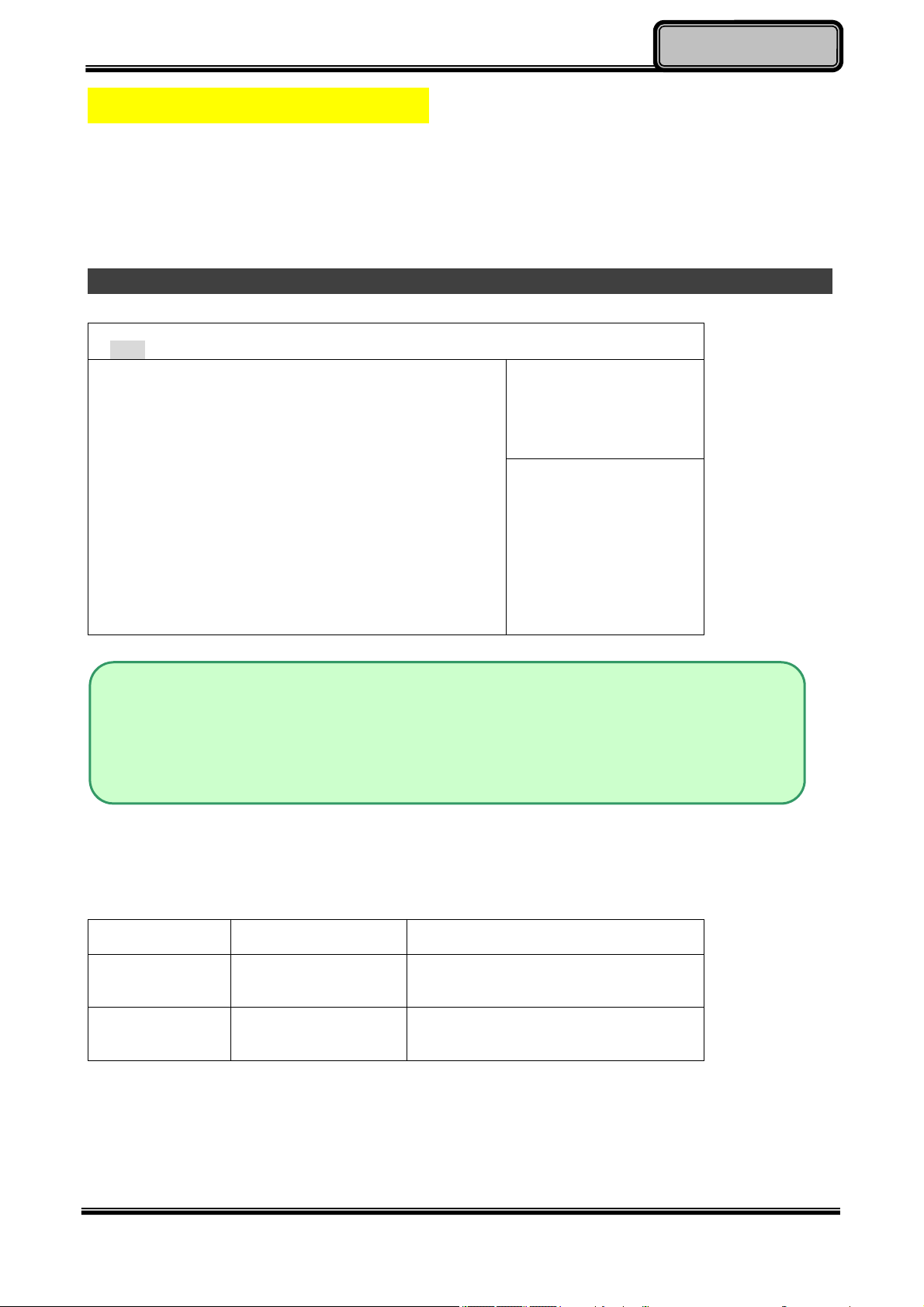
Press [F2] or [Delete] at boot up to enter BIOS setup. Use arrow keys to select options and
[+/-] to modify them. When finished, move to “Exit” and press [Enter] then confirm save by
pressing [Y].
Main Menu
Aptio Setup Utility
Main Advanced Chipset Boot Security Save & Exit
BIOS Information
BIOS Vendor
Core Version
Compliancy
Project Version
Build Date and Time
EC Version
System Language [English]
System Date [Tue 06/02/2015]
System Time [16:19:20]
Access Level Administrator
Choose the system
default language
→←: Select Screen
↑↓: Select Item
Enter: Select
+/–: Change Opt.
F1: General Help
F2: Previous Values
F3: Optimized Defaults
F4: Save & Exit
ESC: Exit
Note:
The contents may vary depending on computer configurations.
Incorrect settings may cause system malfunction. To correct it, restore the
Optimized Defaults with F3.
Main Menu Selections
You can make the following selections on the Main Menu. Use the sub-menus for other
selections.
Feature Options Description
System Date MM/DD/YYYY
Set the system date Month, Day,
Year.
System Time HH:MM:SS
Set the system time Hour, Minute,
Second.
Chapter Four - 32
Page 44
Optional Devices
BIOSSetup
Advanced Menu
Aptio Setup Utility
Main Advanced Chipset Boot Security Save & Exit
► Trusted Computing
► SATA Configuration
► Intel (R) Rapid Start Technology
► USB Configuration
► Super IO Configuration
► RF Device Configuration
► EC Thermal Control
► AC IN BOOT Control
► USB CHARGE Control
► Battery Recalibration
► Intel (R) Smart Connect Technology
► Network Stack Configuration
► Intel 82574L Gigabit Network Connection
Trusted Computing
Setting
→←: Select Screen
↑↓: Select Item
Enter: Select
+/–: Change Opt.
F1: General Help
F2: Previous Values
F3: Optimized Defaults
F4: Save & Exit
ESC: Exit
Chapter Four - 33
Page 45

Advanced Menu Selections
You can make the following selections on the Advanced Menu.
Feature Options Description
Optional Devices
BIOSSetup
Trusted
Computing
SATA
Configuration
Intel (R) Rapid
Start Technology
USB
Configuration
Super IO
Configuration
RF Device
Control
Disabled
Enabled
SATA Mode Selection
SATA Test Mode
Aggressive LPM Support
SATA Controller Speed
Disabled
Enabled
Disabled
Enabled
Serial Port 0~3
Configuration
Disabled
Enabled
Security Device Suppott
SATA Mode Selection:
IDE, AHCI, RAID
Enable or disable Intel (R) Rapid
Start Technology.
Legacy USB Support
USB3.0 Support
XHCI Hand-off
EHCI Hand-off
GSM, GPS, BLUETOOTH, WLAN
EC Thermal
Thermal cooling trip point
Control
AC IN BOOT
Control
USB Charge
Control
Intel Smart
Connect
Disabled
Enabled
Disabled
Enabled
Disabled
Enabled
Technology
Network Stack
Configuration
Intel 82574L
Disabled
Enabled
Gigabit Network
Connection
Enabled to boot the device by
connecting power (Auto Power-On)
Enable/Disable ISCT Configuration
Enable/Disable UEFI Network
Stack
Click to configure the network
device port
Chapter Four - 34
Page 46

Trusted Computing Sub-Menu
Aptio Setup Utility
Advanced
Configuration
Security Device Support [Disable]
Current Status Information
SUPPORT TURNED OFF
Optional Devices
BIOSSetup
Enables or Disables
BIOS support for
security device. O.S.
will not show Security
Device. TCG EFI
protocol and INT1A
interface will not be
available.
→←: Select Screen
↑↓: Select Item
Enter: Select
+/–: Change Opt.
F1: General Help
F2: Previous Values
F3: Optimized Defaults
F4: Save & Exit
ESC: Exit
Chapter Four - 35
Page 47
SATA Configuration Sub-Menu
Aptio Setup Utility
Advanced
SATA Mode Selection [AHCI]
SATA Test Mode [Disabled]
Aggressive LPM Support [Enabled]
SATA Controller Speed [Gen3]
Serial ATA Port 0 Empty
Software Preserve Unknown
Serial ATA Port 1 Empty
Software Preserve Unknown
Serial ATA Port 2 SATA SSD (120.0
Software Preserve SUPPORTED
Optional Devices
BIOSSetup
Determine how SATA
controller(s) operate.
→←: Select Screen
↑↓: Select Item
Enter: Select
+/–: Change Opt.
F1: General Help
F2: Previous Values
F3: Optimized Defaults
F4: Save & Exit
ESC: Exit
SATA Configuration Sub-Menu Selections
You can make the following selections on the SATA configuration sub-menu.
Feature Options Description
SATA Mode
Selection
IDE
AHCI
Determine how SATA
controller(s) operate
RAID
SATA Test Mode Disabled
Enable or disable Test Mode
Enabled
Aggressive LPM
Support
SATA Controller
Speed
Disabled
Enabled
Gen1
Gen2
Enable PCH to aggressively enter
link power state
Indicates the maximum speed the
SATA controller can support
Gen3
Chapter Four - 36
Page 48

Intel (R) Rapid Start Technology Sub-Menu
Aptio Setup Utility
Advanced
Intel (R) Rapid Start Technology [Disabled]
Optional Devices
Enables or disable Intel
(R) Rapid Start
Technology
: Select Screen
→←
↑↓: Select Item
Enter: Select
+/–: Change Opt.
F1: General Help
F2: Previous Values
F3: Optimized Defaults
F4: Save & Exit
ESC: Exit
BIOSSetup
Chapter Four - 37
Page 49
USB Configuration Sub-Menu
Aptio Setup Utility
Advanced
USB Configuration
USB Devices:
1 point
Legacy USB Support [Enabled]
USB3.0 Support [Enabled]
XHCI Hand-off [Enabled]
EHCI Hand-off [Disabled]
Optional Devices
Enables Legacy USB
support.
AUTO option disables
legacy support if no USB
devices are connected.
Disable option will keep
USB devices available
only for EFI applications
: Select Screen
→←
↑↓: Select Item
Enter: Select
+/–: Change Opt.
F1: General Help
F2: Previous Values
F3: Optimized Defaults
F4: Save & Exit
ESC: Exit
BIOSSetup
USB Configuration Sub-Menu Selections
You can make the following selections on the USB configuration sub-menu.
Feature Options Description
Legacy USB
enabled
Disabled
Enabled
Enables Legacy USB support.
AUTO option disables legacy
support if no USB devices are
connected. DISABLE option will
keep USB devices available only
for EFI applications.
Usn3.0
Support
XHCI Hand-off Disabled
Disabled
Enabled
Enabled
Enable/Disable USB3.0 (XHCI)
Controller support.
This is a workaround for OSes
without XHCI hand-off support.
This XHCI ownership change
should be claimed by XHCI
driver.
EHCI Hand-off Disabled
Enabled
This is a workaround for OSes
without EHCI hand-off support.
This EHCI ownership change
should be claimed by EHCI
driver.
Chapter Four - 38
Page 50
RF Device Control Configuration Sub-Menu
Aptio Setup Utility
Advanced
RF Device Control
GSM STATUS Present
GSM [Enabled]
GPS STATUS Present
GPS [Enabled]
BT STATUS Present
BLUETOOTH [Enabled]
WLAN STATUS Present
WLAN [Enabled]
Optional Devices
BIOSSetup
RF Device Control Setting
→←: Select Screen
↑↓: Select Item
Enter: Select
+/–: Change Opt.
F1: General Help
F2: Previous Values
F3: Optimized Defaults
F4: Save & Exit
ESC: Exit
RF Device Control Configuration Sub-Menu Selections
You can make the following selections on the RF Security Control sub-menu.
Feature Options Description
Wireless LAN Disabled
Enabled
WWAN Disabled
Enabled
GPS Disabled
Enabled
BlueTooth Disabled
Enabled
Wireless Lan Control
Enabled Wireless function
WWAN Control
Enabled WWAN function
GPS Control
Enabled GPS function
BlueTooth Control
Enabled Blue Tooth function
Chapter Four - 39
Page 51
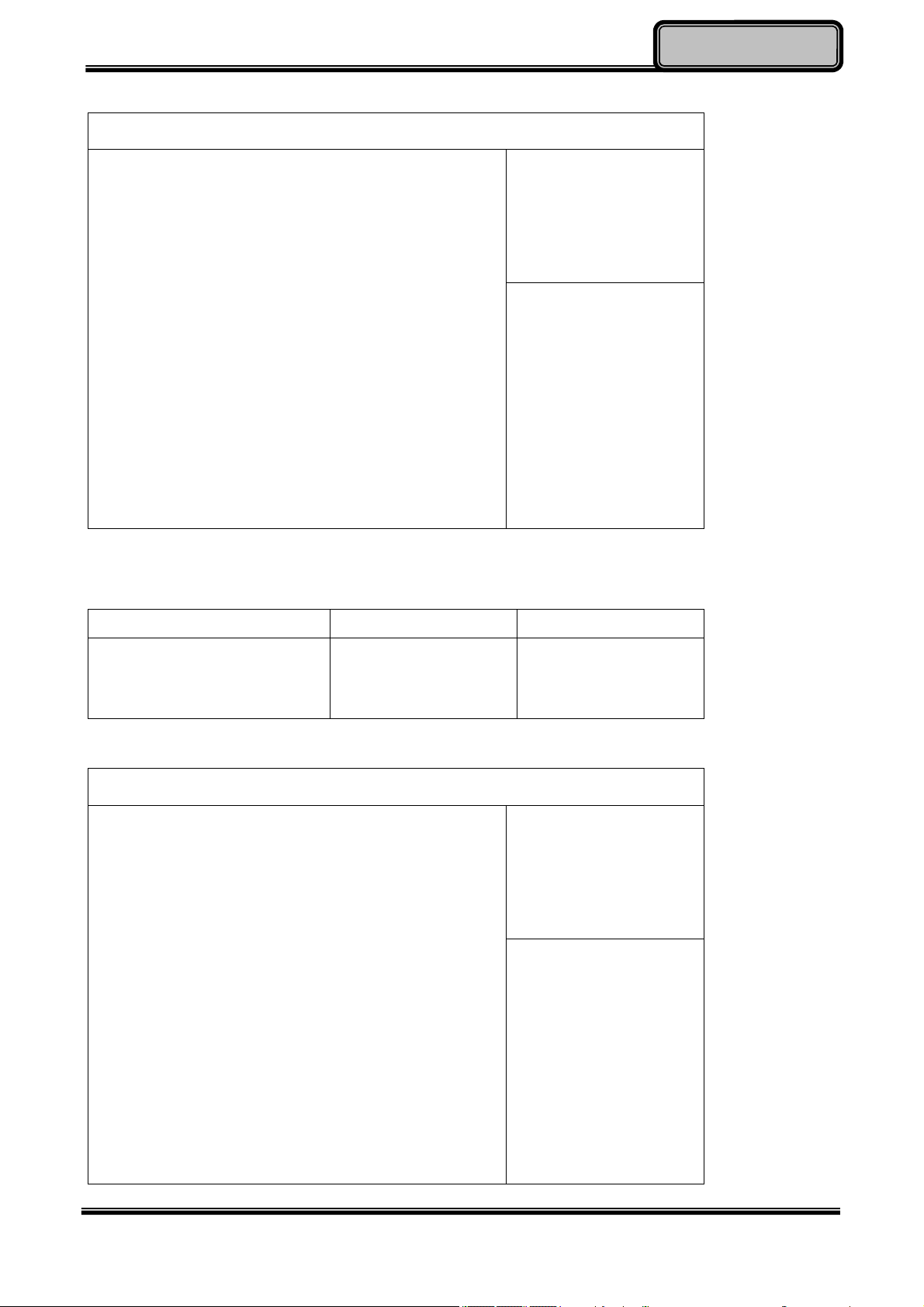
EC Thermal Control Sub-Menu
Aptio Setup Utility
Advanced
EC Thermal Control
Thermal cooling trip point [79 C]
Optional Devices
BIOSSetup
EC Thermal Control
Setting
→←: Select Screen
↑↓: Select Item
Enter: Select
+/–: Change Opt.
F1: General Help
F2: Previous Values
F3: Optimized Defaults
F4: Save & Exit
ESC: Exit
EC Thermal Control Sub-Menu Selections
You can make the following selections on the EC Thermal Control sub-menu.
Feature Options Description
Thermal cooling trip point 71 C
79 C
87 C
AC IN BOOT Control Sub-Menu
Aptio Setup Utility
Advanced
AC IN BOOT
AC IN BOOT Control [Enabled]
AC IN Boot Control
Setting
→←: Select Screen
↑↓: Select Item
Enter: Select
+/–: Change Opt.
F1: General Help
F2: Previous Values
F3: Optimized Defaults
F4: Save & Exit
ESC: Exit
Chapter Four - 40
Page 52

Optional Devices
Note:
The device will automatically boot whenever it is connecting to the AC
power once “AC IN BOOT Control” is enabled.
Default value is set as “disabled”, the change will be activated after
reboot.
BIOSSetup
Chapter Four - 41
Page 53
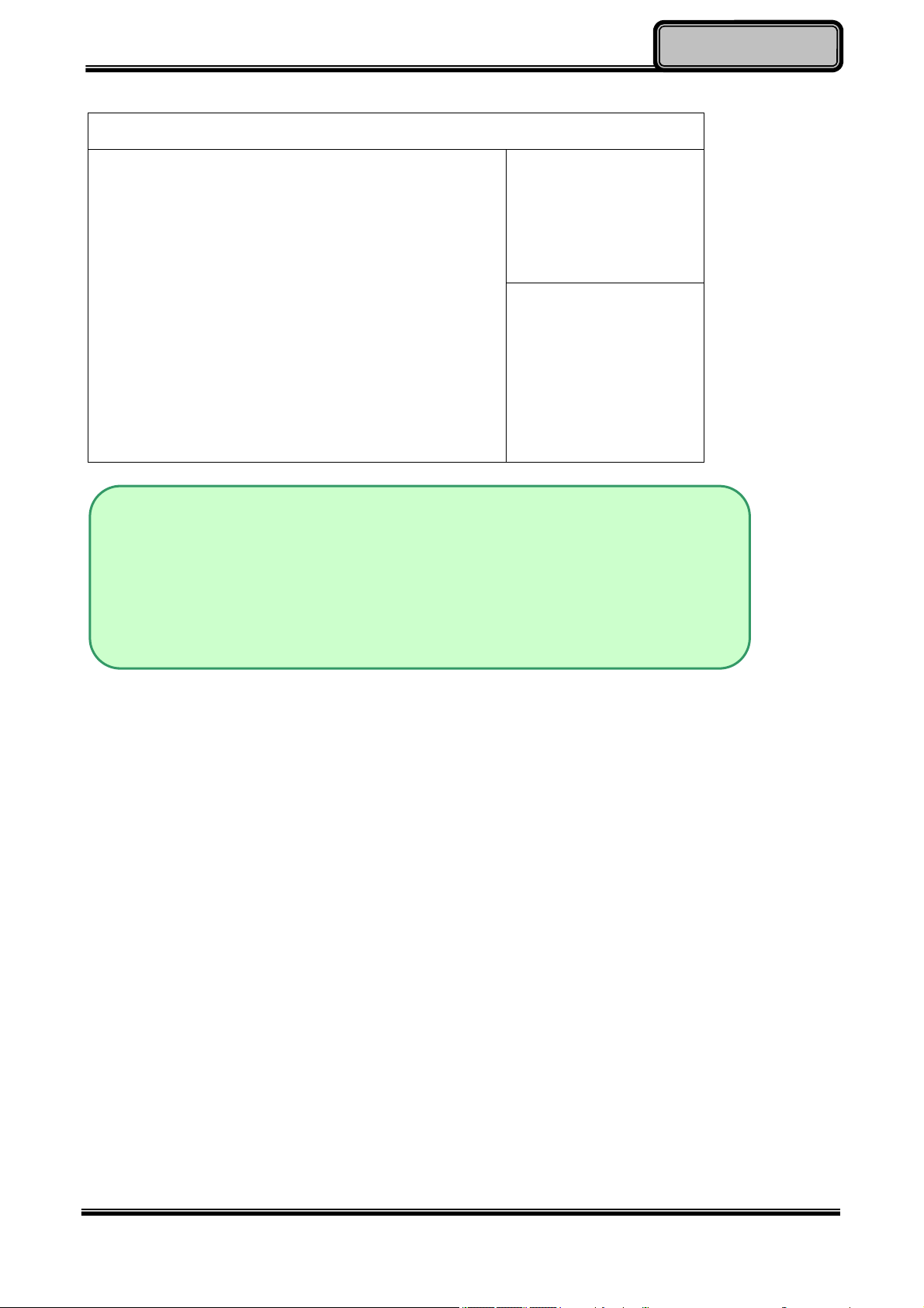
USB CHARGE Control Sub-Menu
Aptio Setup Utility
Advanced
USB CHARGE
USB CHARGE Control [Disabled]
Optional Devices
BIOSSetup
USB CHARGE Setting
→←: Select Screen
↑↓: Select Item
Enter: Select
–/+: Change Opt.
F1: General Help
F2: Previous Values
F3: Optimized Defaults
F4: Save & Exit
ESC: Exit
Note:
USB Charge control is for turn On /Off the USB charge function under
S5 state (Power off) when connecting to AC Adapter
When enable USB CHARGE control in BIOS, please cold boot your
computer to enable the function.
Chapter Four - 42
Page 54
Optional Devices
BIOSSetup
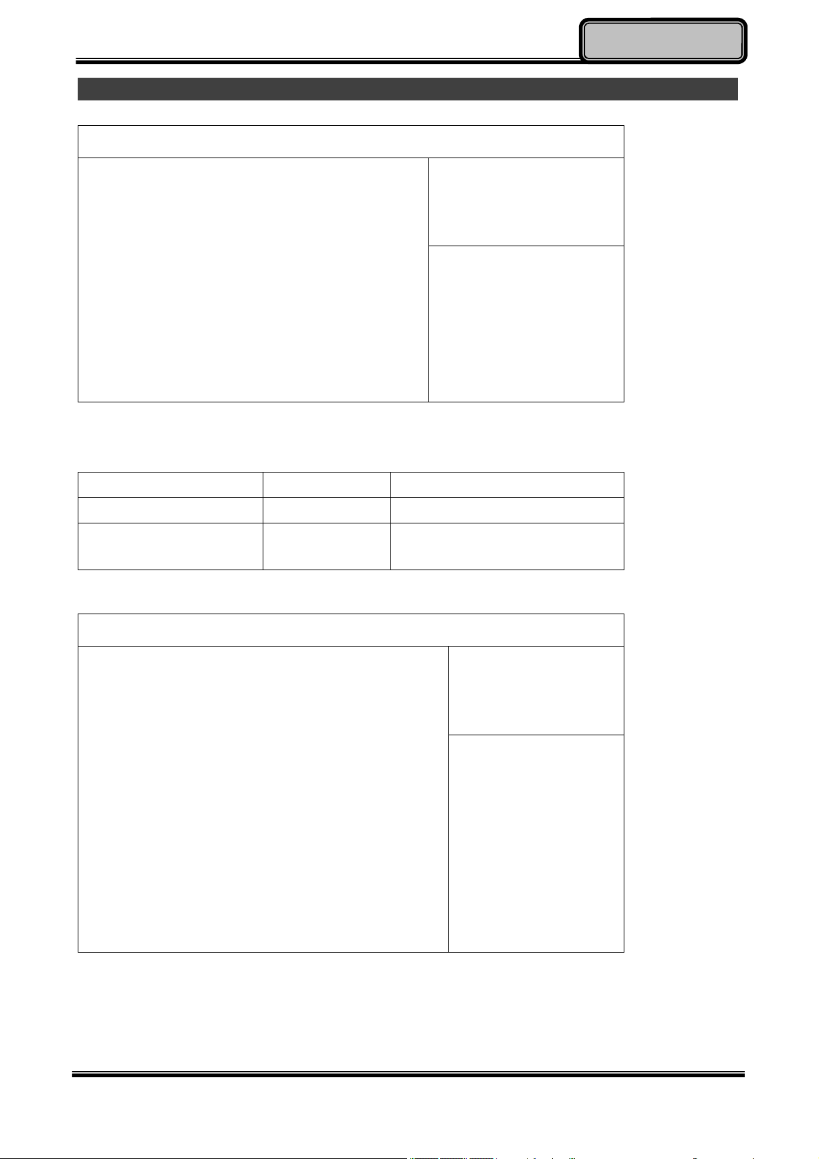
Chipset Menu
Aptio Setup Utility
Main Advanced Chipset Boot Security Save & Exit
► PCH-IO Configuration
► System Agent (SA) Configuration
Chipset Menu Selections
You can make the following selections on the Chipset sub-menu.
PCH Parameters
→←: Select Screen
↑↓: Select Item
Enter: Select
+/–: Change Opt.
F1: General Help
F2: Previous Values
F3: Optimized Defaults
F4: Save & Exit
ESC: Exit
Feature Options Description
PCH-IO Configuration PCH Parameter
System Agent (SA)
Configuration
System Agent (SA)
Parameters
PCH-IO Configuration Sub-Menu
Aptio Setup Utility
Chipset
Intel PCH RC Version 1.6.0.0
Intel PCH SKU Name QM77
Intel PCH Rev ID 04/C1
► PCI Express Configuration
► USB Configuration
► PCH Azalia Configuration
PCI Express
Configuration settings
→←: Select Screen
↑↓: Select Item
Enter: Select
+/–: Change Opt.
F1: General Help
F2: Previous Values
F3: Optimized Defaults
F4: Save & Exit
ESC: Exit
Chapter Four - 43
Page 55

Optional Devices
BIOSSetup
PCH-IO Configuration Sub-Menu Selections
You can make the following selections on the PCH-IO Configuration sub-menu.
Feature Options Description
PCI Express
Configuration
USB
Configuration
PCH Azalia
Configuration
Disabled
Enabled
Disabled
Enabled
Disabled
Enabled
PCI Express Configuration settings
USB Configuration settings
PCH Azalia Configuration settings
Chapter Four - 44
Page 56
Optional Devices
BIOSSetup
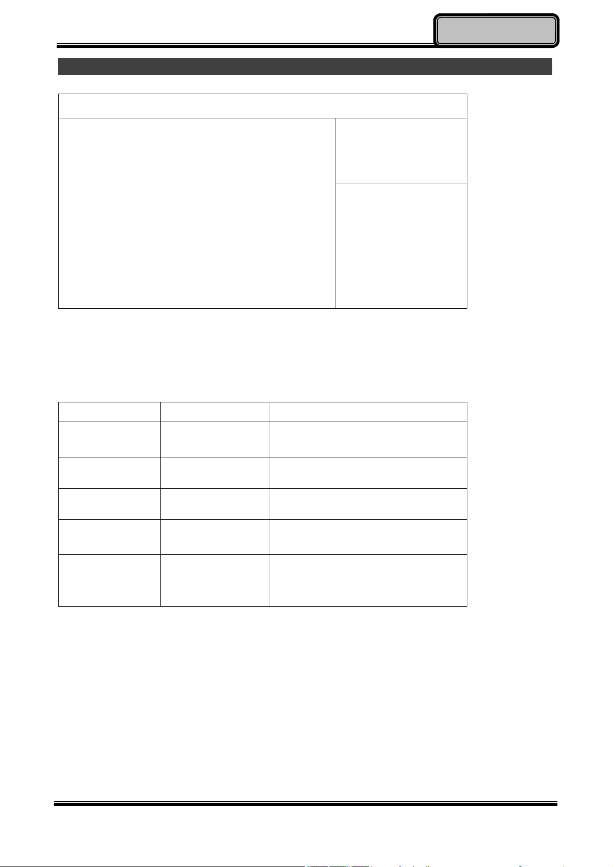
Boot Menu
Aptio Setup Utility
Main Advanced Chipset Boot Security Save & Exit
Boot mode select [Legacy]
Boot Option Priorities
Boot Option #1 [Hard Disk:...]
Boot Option #2 [CD/DVD]
Boot Option #3 [USB Hard Disk]
Boot Option #4 [USB CD/DVD]
Boot Option #5 [USB Key]
Boot Option #6 [USB Floppy]
Boot Option #7 [Network]
► CSM parameters
► Hard Disk Drive BBS Priorities
► Network Device BBS Priorities
The system will try to boot from device on top then the 2nd and so on. If there is more than
one device in each category, only the device on top of sub-menu can boot up.
Boot Menu Selections
You can make the following selections on the Boot menu.
Set boot mode
LEGACY/UEFI
→←: Select Screen
↑↓: Select Item
Enter: Select
+/–: Change Opt.
F1: General Help
F2: Previous Values
F3: Optimized Defaults
F4: Save & Exit
ESC: Exit
Feature Options Description
Boot mode
select
Boot Option
LEGACY
Select boot mode LEGACY/UEFI
UEFI
Sets the system boot order
#1
Boot Option
Sets the system boot order
#2
CSM
parameters
Hard Drive
BBS Priorities
OpROM execution, boot options
filter, etc.
Set the Boot Device Priority
sequence from available Hard
Disk Drives
Chapter Four - 45
Page 57
Optional Devices
BIOSSetup
Security Menu
Aptio Setup Utility
Main Advanced Chipset Boot Security Save & Exit
Password Description
If ONLY the Administrator’s password is set, then this only
limits access to Setup and is only asked for when entering
Setup.
If ONLY the User’s password is set, then this is a power on
password and must be entered to boot or enter Setup. In
Setup the User will have Administrator rights.
The password length must be in the following range;
Minimum length 3
Maximum length 20
Administrator Password
User Password
Secure Boot Menu
HDD Security Configuration:
PO: .xxx
Security Menu Selections
You can make the following selections on the Security Menu.
Set Administrator Password
→←: Select Screen
↑↓: Select Item
Enter: Select
+/–: Change Opt.
F1: General Help
F2: Previous Values
F3: Optimized Defaults
F4: Save & Exit
ESC: Exit
Feature
Administrator
Password
Enter New Password
Confirm New
Options Description
Password
User password Enter New Password
Confirm New
Password
Secure Boot Menu Secure Boot Control
Secure Boot Mode
Controls detection of Processor
Serial No. System must be reset
or restarted from power-on for
settings to take effect.
Supervisor Password controls
access to the setup utility.
Customizable Secure Boot
settings
Chapter Four - 46
Page 58
Optional Devices
BIOSSetup
Save & Exit Menu
Aptio Setup Utility
Main Advanced Chipset Boot Security Save & Exit
Save Changes and Exit
Discard Changes and Exit
Save Changes and Reset
Discard Changes and Reset
Save Options
Save Changes
Discard Changes
Restore Defaults
Save as User Defaults
Restore User Defaults
Boot Override
PO: XXX
IBA GE Slot 0200 v1398
Exit system setup after
saving the changes
→←: Select Screen
↑↓: Select Item
Enter: Select
+/–: Change Opt.
F1: General Help
F2: Previous Values
F3: Optimized Defaults
F4: Save & Exit
ESC: Exit
Chapter Four - 47
Page 59

DriversandApplications
Optional Devices
Chapter 5 – Drivers and Applications
The Utility DVD includes all the drivers for the devices installed in your tablet computer.
Please consult your dealer if there are any driver missing. Also, you could update the driver
or check if there any driver need to be installed by "Windows device manager". Please
check the ”readme.txt” file on Utility DVD to get the information for driver installation.
Chapter Five - 48
Page 60

S
pecifications
Chapter 6 – Specifications
Platform
Intel® Kaby Lake-Y Platform
CPU
Intel® Ivy Bridge i7-7Y75 Processor ,4 MB Cache
Memory
16GB System Memory
- Industrial grade
- LPDDR3 1866MHz
Touch Screen
Type: 10.1” WUXGA (16:10)
Resolution: 1920 x 1200 pixels
Optional Invisible mode on/off
M model:
Resistive Single Touch Screen
Brightness (min.~ typ.): 650~765 nits
I model:
Capacitive Multi Touch Screen
Brightness (min.~ typ.): 780~910 nits
Note:
Invisible Mode On/Off controls all light sources on/off, including LCD B/L, LED
Indicators & Keypad B/L. Invisible Mode trades-off with Fischer conn. x 1.
Storage
Removable mSATA SSD
128GB/256GB/512GB
Industrial Grade
Chapter Six - 49
Page 61
S
pecifications
Buttons/Function Keys
Power button (front side)
Membrane Function Keys with LED Backlight
Audio
HD Audio and mono Speakers
Embedded Digital Mic
I/O Ports
Left:
Standard: Mini DisplayPort x 1/USB3.1 x 2 (the rightmost USB port, with a lightening
mark on the cap, supports fast charging function)
Optional: Mini DisplayPort x 1/USB3.1 x 1 /GLAN x 1
Optional Fischer I/O:
Choose 1~4 out of 6 as below:
- USB 2.0 x 1
- COM x 2 (RS232 x 2 or RS232 x 1/RS422 x 1)
- GLAN x 1
- Audio X 1
- Sealed Headset (Headphone out/Mic-in Combo) x 1
Note:
Sealed headset trades-off with invisible mode switch.
Mini DisplayPort version: DisplayPort 1.1a.
DS13 does not support Dual-Mode DisplayPort(DP++) so an active DisplayPort
adapter is necessary.
Bottom:
Docklite Connector: 32-pin POGO (Hot Swappable)
Ext. ANT Signals x2
Expansion ports:
Standard Micro SD card slot
Chapter Six - 50
Page 62

S
pecifications
Case
CNC milled Aluminum
Color: Black, NATO Green
Dimensions and Weight
Dimensions (mm):
286 (L) x 193 (W) x 27 (H) (with Bumpers)
Weight: 1.39kg (With battery)
1.09kg (Without battery)
Note:
Weight varies depending on system configurations.
Power
Battery Pack:
Type: Prismatic Lithium Ion Cell
Capacity: 11.1V/ 4200mAh (3S2P)
Dimensions: 138 mm (W) x 136 mm (D) x 9.7 mm (H)
Weight: Approx. 300 gram (0.66 lb.)
AC Adapter
Input Voltage: AC 100 - 240V
Frequency: 50/60 Hz
Output Voltage: DC 19V
Maximum Power: 90 Watts
Dimensions: 133 mm (W) x 58mm (D) x 30mm (H)
Weight: Approx. 400 g (0.88 lb.)
DC-In:
12~32V
- Fischer 3 pin Connector
Chapter Six - 51
Page 63

S
pecifications
Environmental, Safety & EMC
CE, FCC, WEEE, REACH, RoHS, IP65, MIL-STD-810G, MIL-STD-461G
Operating & Storage Temperature
Operating Temp.:
- Standard: -20 °C ~ +60 °C*
- Optional: -30 °C ~ +60 °C*
*LCD with Heater
Storage Temp.: -40 °C ~ +70 °C
Materials and Recycling
Materials of the computer are as follows:
Magnesium case: AL6061T6
PCB: FR-4, UL 94V0
Battery: Rechargeable Lithium Ion cells
Packing: Carton: Unbleached paper
Cushion: Recyclable PE
Carrying bag: Recyclable PE Fiber
Quick Guide: Paper
Please recycle the parts according to local regulations.
Chapter Six - 52
Page 64

OptionalDevices
Chapter 7 – Optional Devices
Communication
WiFi/Bluetooth:
- Intel Dual Band wireless- AC 8265
- Board Form Factor: M.2 2230 E-key Card
- Wi-Fi Certified: 802.11 a/b/g/n/ac
- Bluetooth: Supports BT 4.2 (Backward compatible)
- Interface: PCIe (WiFi)/USB (BT)
GPS:
- U-blox M8N (USB interface)
Security
BIOS password and Kensington cable lock slot are available to safely secure your
computer. Optional TPM (Trusted Platform Module) version 2.0 is also supported,
preventing unauthorized access to your computer.
AMG Sensor Module
AMG Sensor Module is designed for automatic screen rotation when you turn the tablet
computer from landscape to portrait and back. It is especially convenient for you to turn to
an appropriate view when using different apps.
Mil. Fischer Connector
Optional Fischer connectors provide solutions for users to operate the device in harsh
environments. Signals designed for usage include USB2.0, VGA, RS232 or RS422, GLAN,
and Audio.
External Vehicle Adapter
The External Vehicle Adapter, EVA1275, is designed to directly connect equipment to the
vehicle power system, converting the input voltage 12~32V to output 19V. Fischer 3-pin
plug is available designed for DS11.
Chapter Seven - 53
Page 65
OptionalDevices
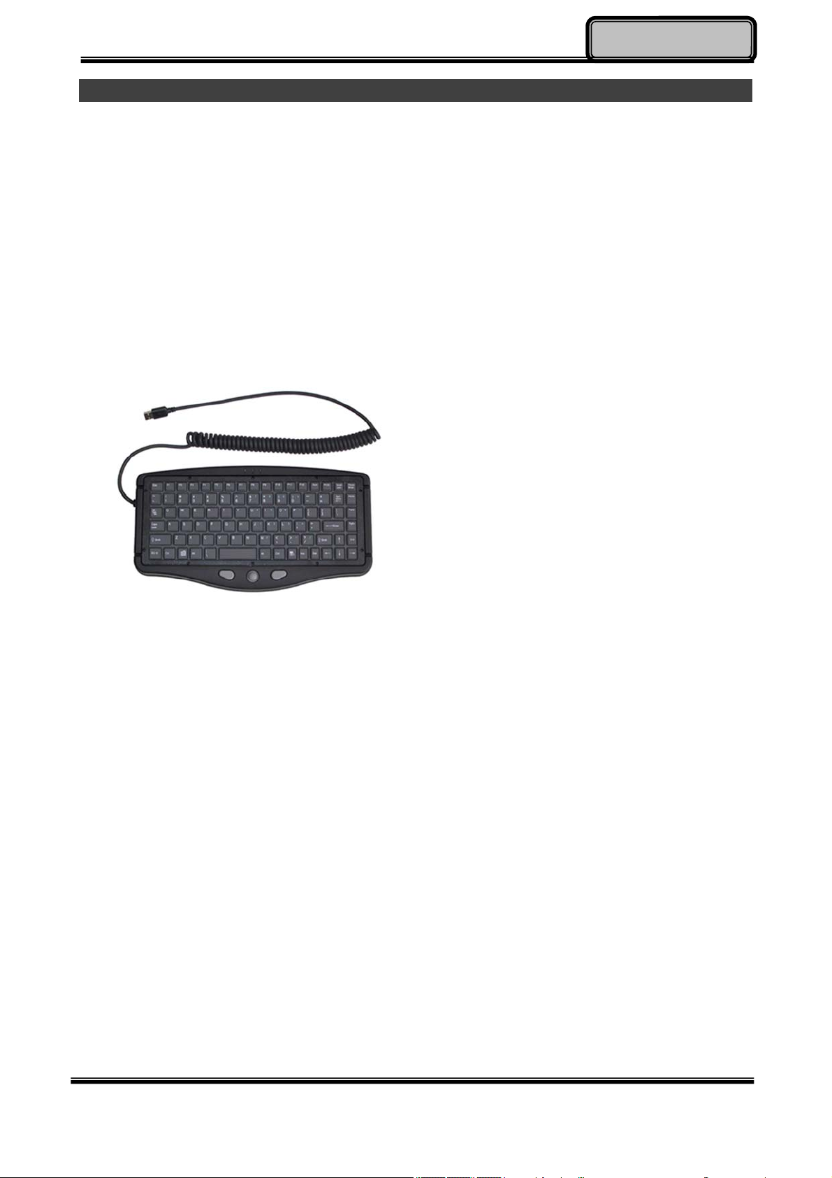
External USB Keyboard
An optional 89-key external USB keyboard with LED backlight and IP rating of IP54 is
available for your tablet computer. The detailed specification is provided below:
89-key layout emulates 101/102-key KB
Life: >1 million times, water/dust protection up to IP54
Back-light illumination (backlight device: green LED)
PS/2 compatible Trackpoint and mouse buttons
Dimensions: 323.4 mm (W) x 172 mm (D) x 25 mm (H)
Weight: 1.1 kg
Track point
The track point is functionally equivalent to a mouse. Pushing the track point may move the
cursor on the screen. The 2 buttons act same as mouse buttons.
Backlight
Press [I-O] key for approximately 1 second turns keyboard backlight ON or OFF.
Chapter Seven - 54
Page 66
OptionalDevices
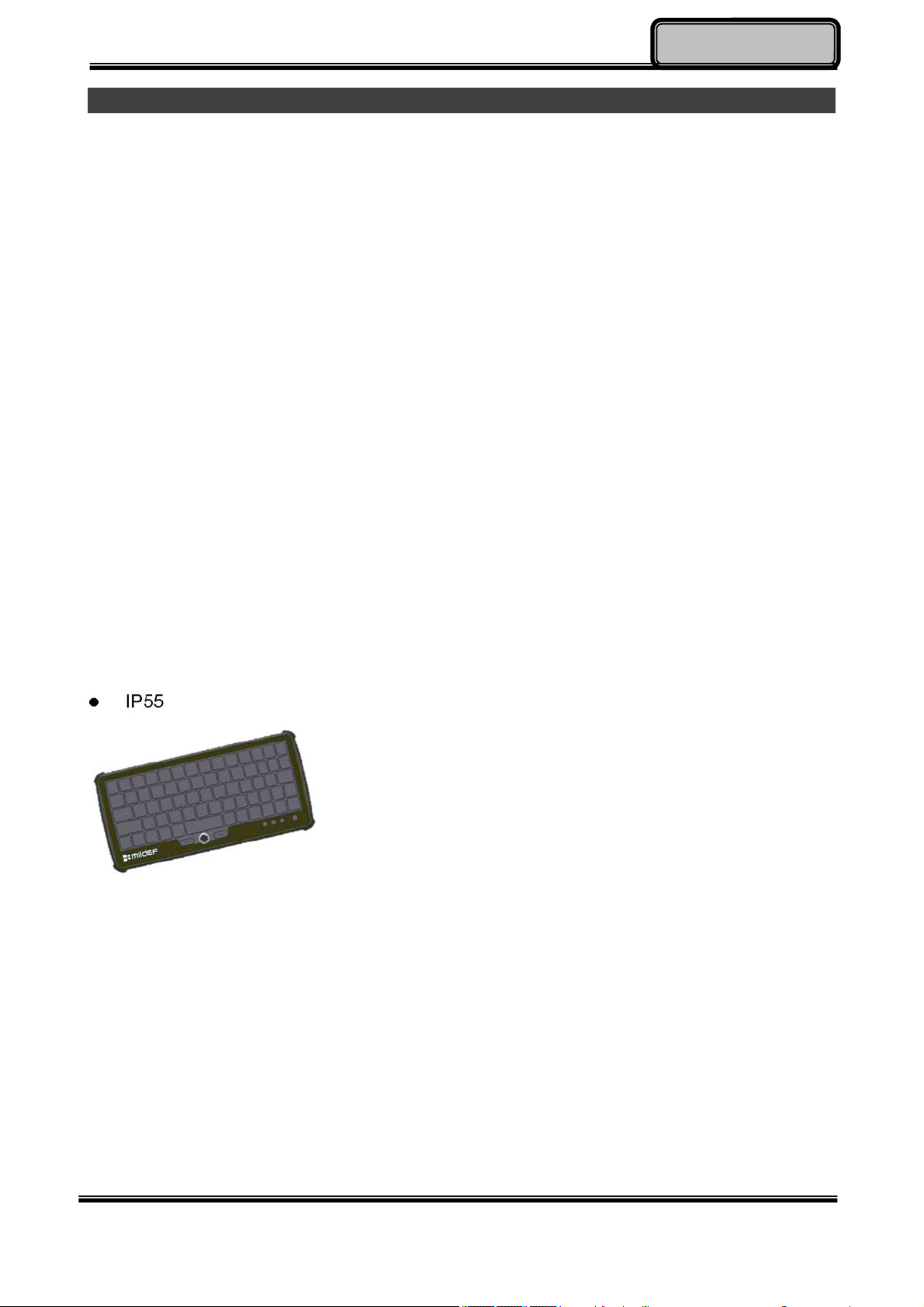
Mini Keyboard KBD
Mini Keyboard KBD is designed for all models. KBD also brings convenience of use through
multi-language keyboard versions and USB interface. The detailed specification is provided
below:
USB interface with 30 cm USB cable
66-Key design with function keys to simulate standard keyboards.
StickPointer to simulate mouse and keypad
Currently support versions:
English (UI), English (UK), German (DE), Swedish (SV) and Russian (RU) 5 versions.
LED Backlight
Caps Lock, Number Lock, Scroll Lock, and Smart Card Reader LED Indicators
Magnesium Alloy Case (Black)
Operating Temperature: -20 ~ 50ºC (-4 ~ 122ºF)
Storage Temperature: -40 ~ 70ºC (-40 ~ 158ºF)
Optional Built-in Smart Card Reader
Dimensions: 190 mm (W) x 90 mm (D) x 12 mm (H)
Weight: 170 g
IP55
Chapter Seven - 55
Page 67

Chapter 8 – Maintenance and Service
Cleaning
ALWAYS turn OFF the power, unplug the power cord and remove the battery before
cleaning.
The exterior of the system and display may be wiped with a clean, soft, and lint-free cloth.
If there is difficulty removing dirt, apply non-ammonia, non-alcohol based glass cleaner to
the cloth and wipe.
An air gun is recommended for cleaning water and dust. For salty water please clean with
fresh water then blow-dry with an air gun.
Troubleshooting
Should the tablet computer fail to function properly, the troubleshooting steps below may
be followed.
Power Problems:
When I turn on the Tablet computer, it does not respond.
- If you are using battery power, check if the battery is charged
- If you are using AC power, ensure that the connection of AC adapter is correct.
I cannot return from Hibernation while on battery power
- The battery might be drained. Please plug the tablet into AC power.
- Hard reset the device by pressing the power button for 4 seconds
Unexpected or improper shutdown causes BIOS to reset to Optimized Default
- This could be a power problem. Please connect the AC power adapter to fix the
abnormal shutdown problem.
Minimize the configuration, i.e. remove extra peripherals and devices.
Remove the modules one by one (SSD, Battery, etc.).
Remove the software suspected.
Set BIOS fail-safe default.
Re-install operating system and application software.
Page 68

RMA Service
If troubleshooting solutions are unsuccessful, consult your dealer for RMA.
Shipping instructions:
1. Remove any personal add-on devices or other media.
2. Use the original shipping container and packing materials, if possible.
3. If the original packing materials are not available, wrap the equipment with soft
material (e.g. PU/PE form) then put the wrapped equipment into a hard cardboard
shipping box.
4. Include a sheet with the following information: (Note: Please keep a copy of this sheet
for your records.)
- Name
- Address
- Unit serial number
- Place and date of purchase or the original invoice number
- Date of failure
- A DETAILED description of the problems you have encountered including: The
operating system, the add-on device installed (if any), the application software, the
failure phenomenon, etc.
- A list of the hardware/software configuration, if applicable.
5. Clearly mark the outside of the shipping box with the RMA #. If an RMA # is not
present on the shipping box, receiving will be unable to identify it and it might be
returned.
6. Unless prior arrangements have been made, the customer is responsible for all
shipping costs. Unauthorized use of the company’s shipping accounts is not
permitted.
 Loading...