

Page 1
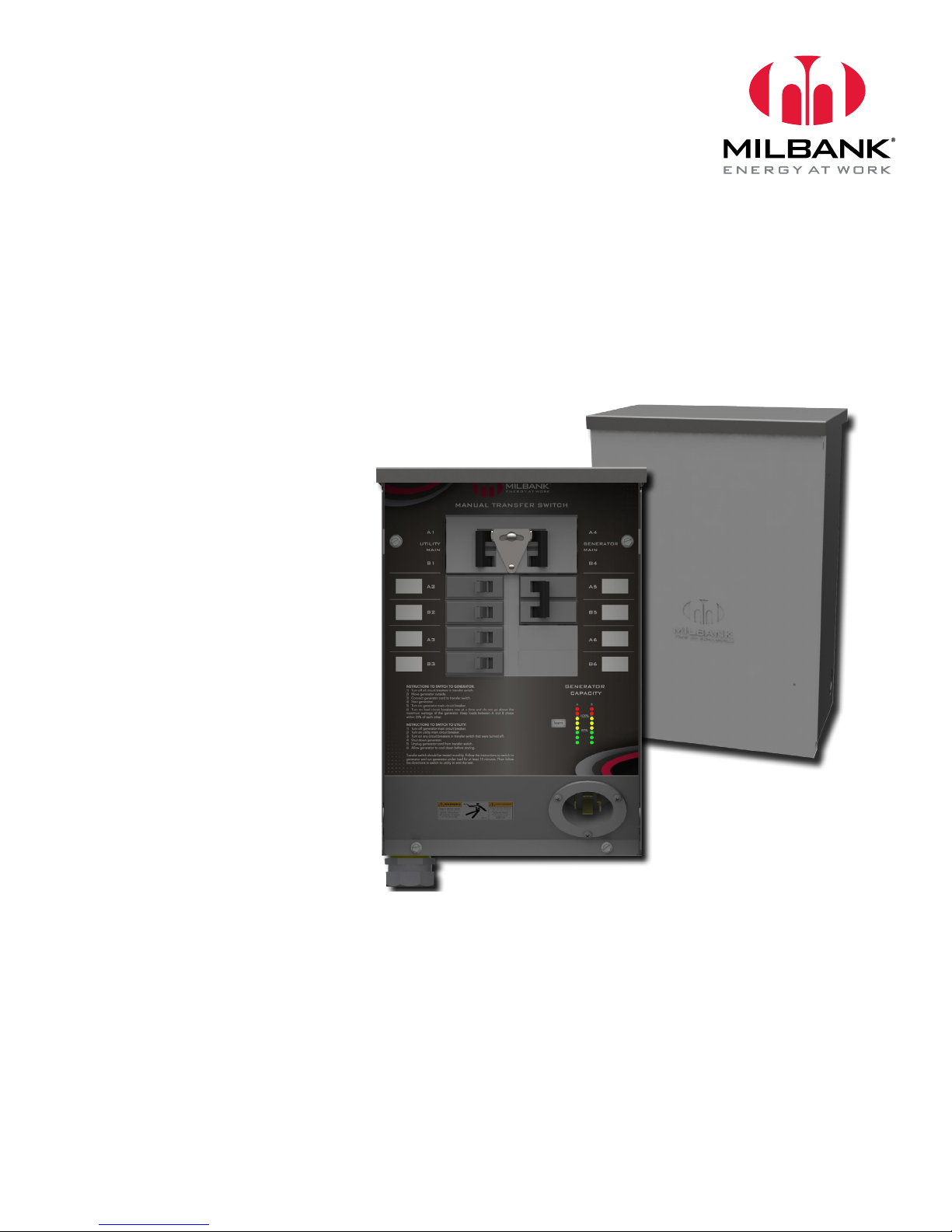
MILBANK MANUAL TRANSFER SWITCH
30 & 50 AMP
OWNER’S & INSTALLATION MANUAL
MODEL #
MMTS301SYS
MMTS301
MMTS501SYS
MMTS501
Revision 1.1
BOM # 1171740
3.26.15
Milbank | 4801 Deramus Ave., Kansas City, MO 64120 | 877.483.5314 | milbankworks.com
Page 2

California
Proposition 65 Warning
Certain components in this product and its related accessories contain
chemicals known to the state of California to cause cancer, birth defects or
other reproductive harm. Wash hands after handling.
DISCLAIMERS:
All information, illustrations and specications in this manual are based on the latest information available at
the time of publishing. The illustrations used in this manual are intended as representative reference views only.
Moreover, because of our continuous product improvement policy, we may modify information, illustrations and/or
specications to explain and/or exemplify a product, service or maintenance improvement. We reserve the right to
make any change at any time without notice. Some images may vary depending upon which model is shown.
ALL RIGHTS RESERVED:
No part of this publication may be reproduced or used in any form by any means – graphic, electronic or
mechanical, including photocopying, recording, taping or information storage and retrieval systems – without the
written permission of Milbank Manufacturing.
ORIGINAL INSTRUCTIONS (English):
The English version of this manual controls over any error in or conicting interpretation of any translation.
2 Milbank Manual Transfer Switch Owner’s and Installation Manual
Page 3

TABLE OF CONTENTS
INTRODUCTION ................................................................................................................4
CONTACT INFORMATION .....................................................................................................................4
TM
MANUAL TRANSFER SWITCH
GENERATOR .........................................................................................................................................5
END USER RESPONSIBILITIES ............................................................................................................ 5
LICENSED ELECTRICIAN RESPONSIBILITIES ....................................................................................5
IMPORTANT SAFETY INSTRUCTIONS ............................................................................6
SAFETY SYMBOL MEANINGS .............................................................................................................6
GENERAL SAFETY PRECAUTIONS......................................................................................................8
OPERATION AND INSTALLATION .................................................................................. 10
INSTALLATION ....................................................................................................................................10
Package Contents .......................................................................................................................... 10
Unpacking and Handling ................................................................................................................ 11
MMTS Wiring Diagram ...................................................................................................................11
Installation Diagram ........................................................................................................................ 12
FUNCTIONAL TESTING ......................................................................................................................13
Electrical ......................................................................................................................................... 13
MOUNTING DIMENSIONS ..............................................................................................14
SET UP ..............................................................................................................................15
GENERATOR CAPACITY DISPLAY & LEARN FUNCTION: ................................................................15
SETTING THE LEARN FUNCTION ...................................................................................................... 16
RESETTING LEARN VALUE ................................................................................................................16
NORMAL OPERATION ........................................................................................................................17
TROUBLESHOOTING ...................................................................................................... 18
RADIO AND TELEVISION INTERFERENCE ........................................................................................18
MAINTENANCE ................................................................................................................................... 18
MILBANK TRANSFER SWITCH OWNER WARRANTY POLICY ...................................19
WARRANTY PERIOD...........................................................................................................................19
Warranty Registration Process .......................................................................................................19
About your warranty ....................................................................................................................... 19
REPLACEMENT PARTS IDENTIFICATION ..........................................................................................20
SPECIFICATIONS .............................................................................................................21
QUICK START GUIDE ...................................................................................................... 22
INDEX .............................................................................................................................................22
LEARN PROCESS .......................................................................................................................... 23
FAQS ..............................................................................................................................................23
.......................................................................................................... 5
Milbank Manual Transfer Switch Owner’s and Installation Manual 3
Page 4

INTRODUCTION
Thank you for your purchase of a Milbank Manual
Transfer Switch (MMTS). This product is designed for
use with portable generators. This Manual Transfer
Switch may have different installation requirements
depending on the generator manufacturer or design.
When operated and maintained according to the
instructions in this manual, your system will provide
many years of electrical energy service for utility
outages.
This Manual Transfer Switch requires professional
installation before use. Refer to the installation
section of this manual for instructions on installation
procedures. Only licensed electricians should install
the MMTS.
This manual contains important safety instructions for
installation and operation of this MMTS. Every effort
was made to provide safe, efcient instructions for
installation and operation. However, as all installations
are unique, it is impossible to anticipate every possible
procedure and method to achieve a properly installed
unit. It is important that you read and understand these
instructions thoroughly before attempting to install or
operate this unit. Your equipment is supplied with this
combined Owner’s and Installation Manual. This is an
important document and should be retained by the
owner after the installation has been completed. An
electronic version can be downloaded at milbankworks.
com.
CONTACT INFORMATION
There are several ways to contact us for answers to
questions you may have about your product. Please
contact Technical services by phone at (816) 410-
7346, Monday through Friday 8a.m. to 5 p.m, Central
Time. Electronic communication can be made through
our website milbankworks.com where you can
locate an authorized repair technician, or by email at
techservices@milbankworks.com.
Every effort has been made to ensure that the information
in this manual is both accurate and current; however,
the manufacturer reserves the right to change, alter or
otherwise improve the system at any time without prior
notice.
This User and Installation Guide describes how
to install, congure, and use the Milbank Manual
Transfer Switch (MMTS). This manual describes the
conguration, features, and operation of models
MMTS301SYS and MMTS501SYS. The MMTS301 and
MMTS501 is a reduced functionality unit that does not
include the power monitoring feature.
The instructions are to be used to properly install and
congure the Manual Transfer Switch to the home wiring
system. Installations must comply with all federal,
state and local codes, standards and regulations. Your
installer should follow these instructions completely.
This manual only covers the MMTS operation, the
portable generator manual is to be used for proper
operation of the generator.
4 Milbank Manual Transfer Switch Owner’s and Installation Manual
Page 5

INTRODUCTION
For your future reference please record the following pertinent information. This information will help to identify
product information should you need to contact Milbank’s Technical Services department.
MANUAL TRANSFER SWITCH
Model Number:
Description:
Serial Number:
Installation Date: _________________________________
GENERATOR
Model Number: __________________________________
Description: ______________________________________
Serial Number: ___________________________________
Installation Date: _________________________________
END USER RESPONSIBILITIES
To ensure you make informed choices and decisions, communicate effectively with your licensed electrician and
familiarize yourself with the installation options available. The equipment warranty is void unless the system is
installed by a licensed electrician. All installations of Milbank systems must comply with all applicable codes,
industry standards, and regulations. Your installer must check local codes and obtain permits before installing the
system.
LICENSED ELECTRICIAN RESPONSIBILITIES
• Read and observe the safety rules.
• Read and follow instructions given in this manual.
• Check federal, state, and local codes and authority having jurisdiction for questions on installation.
• Ensure the generator is not overloaded with selected loads.
• Perform an installation that will pass the nal electrical inspection.
TO BE SUPPLIED BY INSTALLER:
• Connecting wire and conduit
• Tools and equipment needed to perform the installation
Milbank Manual Transfer Switch Owner’s and Installation Manual 5
Page 6
SAFETY
!
!
!
!
!
IMPORTANT SAFETY INSTRUCTIONS
SAVE THESE INSTRUCTIONS.
• This manual contains important information that should be used during installation, maintenance and operation
of this unit.
SAFETY LABELS
WARNING
Only qualied electricians should attempt
installation of this equipment, which must
strictly comply with all applicable codes,
standards and regulations.
Certain components in this product and
related accessories may contain chemicals
known to the State of California to cause
cancer, birth defects, or other reproductive
harm.
Wash hands after handling.
The safety alert symbol indicates a potential
personal injury hazard. A single word (DANGER,
WARNING, OR CAUTION) is used with the alert
symbol to designate a degree or level of hazard
seriousness. A safety symbol may be used to
represent the type of hazard. The signal word
NOTICE is used to address practices not related
to personal injury.
DANGER
Indicates a hazardous situation which, if not avoided,
will result in death or serious injury.
WARNING
Indicates a hazardous situation which, if not avoided,
could result in death or serious injury.
CAUTION
Indicates a hazardous situation which, if not avoided,
could result in minor or moderate injury.
6 Milbank Manual Transfer Switch Owner’s and Installation Manual
NOTICE addresses practices not related to personal
injury.
The manufacturer of this product cannot reasonably
anticipate every possible circumstance that might
involve a hazard. The warnings in this manual, and
the tags and decals afxed to the unit are therefore,
not all-inclusive. If you use a procedure, work
method or operating technique that the manufacturer
does not specically recommend, work method or
operating technique that you choose does not render
the equipment unsafe.
Page 7
SÉCURITÉ
!
!
!
!
!
IMPORTANT SAFETY INSTRUCTIONS
CONSERVER CES INSTRUCTIONS
• Ce manuel contient des informations importantes qui doivent être utilisés lors de l’installation, l’entretien et le
fonctionnement de cet appareil.
SÉCURITÉ SYMBOLE SIGNIFICATION
AVERTISSMENT
Seuls des électriciens qualiés devraient
tenter l’installation de cet équipement, qui
doit se conformer strictement aux codes,
aux normes et réglementations.
Certains composants de ce produit et les
accessoires connexes peuvent contenir
des produits chimiques reconnus par l’État
de Californie pour causer le cancer, des
malformations congénitales ou d’autres
problèmes de reproduction.
Se laver les mains après manipulation.
Le symbole d’alerte de sécurité, indique un danger
potentiel de blessures. Un seul mot (DANGER,
AVERTISSEMENT ou ATTENTION) est utilisé avec
le symbole d’alerte pour indiquer le degré ou niveau
de risque sérieux. Un symbole de sécurité peut
être utilisé pour représenter le type de risque. Le
mot AVIS de signal est utilisé pour lutter contre les
pratiques ne sont pas liées à des blessures.
DANGER
Indique un risque qui, s’il n’est pas évité, entraînera la
mort ou des blessures graves.
AVERTISSMENT
Indique un danger qui, s’il n’est pas évitée, peut entraîner
la mort ou des blessures graves.
ATTENTION
Indique un danger qui, s’il n’est pas évité, pourrait
entraîner des blessures mineures ou modérées.
Milbank Manual Transfer Switch Owner’s and Installation Manual 7
AVIS pratiques les adresses ne sont pas liés à des
blessures.
Le fabricant de ce produit ne peut pas raisonnablement
anticiper toutes les circonstances potentielles pouvant
comporter un danger. Les avertissements dans ce
manuel, et les balises et les décalques apposés sur
l’appareil sont donc pas exhaustive. Si vous utilisez
une procédure, une méthode de travail ou la technique
d’exploitation que le fabricant ne recommande pas
spéciquement, vous devez vous assurer qu’il est
sécuritaire pour vous et les autres. Vous devez également
vous assurer que la procédure, la méthode de travail ou
la technique d’exploitation que vous choisissez ne rende
pas l’équipement dangereux.
Page 8
SAFETY
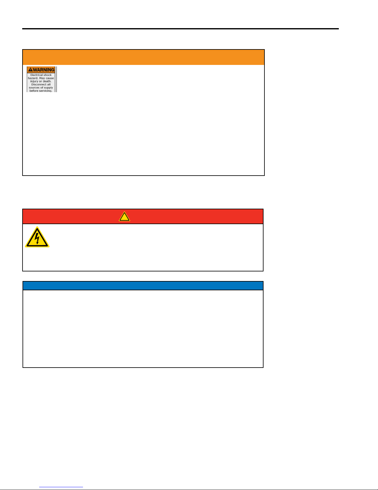
!
WARNING
Failure to properly ground equipment can result in electrocution.
• Do not touch bare wires.
• Do not use equipment with worn, frayed, bare or otherwise damaged
wiring.
• Do not handle electrical cords while standing in water, while barefoot, or while hands or
feet are wet.
• If you must work around a unit while it is operating, stand on an insulated dry surface to
reduce shock hazard.
• Do not allow unqualied persons or children to service equipment.
• In case of an accident caused by electrical shock, immediately shut down all sources of
electrical power and contact local authorities. Avoid direct contact with the victim.
GENERAL SAFETY PRECAUTIONS
DANGER
DANGER! Equipment contains high voltage that can cause personal injury or
death.
Despite the safe design of the system, operating this equipment imprudently,
neglecting its maintenance or being careless can cause possible injury or
death.
NOTICE
Improper treatment of equipment can damage it and shorten its life.
• Use equipment only for intended uses.
• If you have questions about intended use, ask dealer or contact Milbank
Manufacturing.
• Do not expose equipment to excessive moisture, dust, dirt, or corrosive vapors.
• Remain alert at all times while working on this equipment. Never work on the
equipment when you are physically or mentally fatigued.
• If connected devices overheat, turn them off and turn off their circuit breaker/fuse.
8 Milbank Manual Transfer Switch Owner’s and Installation Manual
Page 9

!
AVERTISSMENT
Un défaut de terre le matériel peut entraîner une électrocution.
• Ne pas toucher les ls nus.
• Ne pas utiliser de matériel avec des cordons électriques usés,
eflochés ou dénudés, ou autrement endommagé.
• Ne pas manipuler les ls électriques tout en restant dans l’eau, pieds nus ou avec les
mains ou les pieds mouillés.
• Si vous devez travailler autour d’une unité pendant son fonctionnement, tenir sur une
surface sèche isolée pour réduire les risques de choc.
• Ne laissez pas des personnes non qualiées ou des enfants pour le matériel.
• Dans le cas d’un accident causé par un choc électrique, arrêter immédiatement toutes les
sources d’alimentation électrique et contacter les autorités locales. Eviter le contact direct
avec la victime.
PRÉCAUTIONS GÉNÉRALES DE SÉCURITÉ
SÉCURITÉ
DANGER
DANGER! Équipement contient haute tension qui peut provoquer des
blessures ou la mort.
En dépit de la conception sécuritaire du système, d’utiliser cet équipement
de façon imprudente, négliger son entretien ou être négligent peut causer
des blessures ou la mort.
AVIS
Le traitement inadéquat de l’équipement peut endommager et de raccourcir sa durée de vie.
Use equipment only for intended uses.
• Si vous avez des questions concernant les utilisations prévues, demandez à votre
distributeur ou contactez Milbank fabrication.
• Ne pas exposer le matériel à l’humidité, la poussière, la saleté ou à des vapeurs
corrosives.
• Demeurez alerte en tout temps lorsque vous travaillez sur cet équipement.
Ne jamais travailler sur l’équipement si vous êtes fatigué physiquement ou
mentalement.
• Si les appareils branchés sont en surchauffe, éteignez-les et mettez leur
disjoncteur / fusible.
Milbank Manual Transfer Switch Owner’s and Installation Manual 9
Page 10

PACKAGE CONTENTS
Before installation, please refer to the following chart to ensure you have received the appropriate components for your model
of Manual Transfer Switch.
MILBANK 30A MANUAL SWITCH OPTIONS
MMTS301
MMTS301L
MMTS301SYSX
MMTS301SYSX1C
MMTS301SYSX2C
MMTS301SYSL
MMTS301SYSL1C
MMTS301SYSL2C
MMTS501
MMTS501L
MMTS501SYSX
MMTS501SYSX1C
MMTS501SYSX2C
MMTS501SYSL
MMTS501SYSL1C
MMTS501SYSL2C
60A Utility
Breaker
X X
X X X
X X X X X X
X X X X X X X
X X X X X X X
X X X X X X
X X X X X X X
X X X X X X X
30A
Generator
Breaker
6 Branch
Breakers
6’ Wiring
harness
Included
30A Inlet
Installed in
MTS
LED Digital
Meter with
Learn
Function
Separate
power inlet
box with
30A Plug
(Nema 3R)
10’ Cord 25’ Cord
MILBANK 50A MANUAL SWITCH OPTIONS
100A Utility
Breaker
X X
X X X
X X X X X X
X X X X X X X
X X X X X X X
X X X X X X
X X X X X X X
X X X X X X X
50A
Generator
Breaker
6 Branch
Breakers
6’ Wiring
harness
Included
50A Inlet
Installed in
MTS
LED Digital
Meter with
Learn
Function
Separate
power inlet
box with
50A Plug
(Nema 3R)
10’ Cord 25’ Cord
10 Milbank Manual Transfer Switch Owner’s and Installation Manual
Page 11

OPERATION & INSTALLATION
Utilizing a portable generator, your Manual Transfer Switch
will power to selected circuits in the event that utility power
is interrupted. The MMTS normal operation is to connect
the Utility to the selected circuits using the internal Load
Subpanel. The MMTS system can manually switch up to 8 AC
circuits when operating on generator power. MMTS301SYS
and MMTS501SYS systems monitors and displays power
being consumed by the selected circuits, using Light Emitting
Diodes (LED’s), to allow the home owner to manually control
the loads on the generator. A survey of power usage of the
selected circuits should be performed to achieve the desired
performance from the portable generator.
UNPACKING AND HANDLING
After unpacking inspect the Manual Transfer Switch for any
damage that may have occurred during shipping. If any
missing parts or damage is discovered when unpacking, do
not return the unit to the place of purchase; please contact
Milbank Technical Services for instructions on how to
proceed. Never install a Manual Transfer Switch that has been
damaged.
The MMTS enclosure is NEMA type 3R rated and is suitable
for indoor or outdoor installations.
Guidelines for mounting the unit include:
• Ensure that mounting surface can support the 25 pound
weight of the MMTS and adheres to all local codes
• The enclosure must be installed with NEMA type 3R
hardware and connections
• Level and plumb the unit enclosure to prevent deformation
• Never install the MMTS where any corrosive substance may
come in contact with the enclosure
• Protect the MMTS at all times against excessive moisture,
dust, dirt, lint, construction grit and corrosive vapors
• An optional inlet box can be used to permit installing the
generator outside while installing the MMTS inside next to
the Main distribution panel/ load center
MMTS WIRING DIAGRAM
Figure 1 – Manual Transfer Switch Diagram
The schematic shows the internal wiring of
the MMTS with the Manual Transfer Switch
Indicator Printed Circuit Board (MTSI PCB)
assembly. The MTSI PCB uses 2 current
transformers to acquire power for the
monitoring circuitry and to measure power
in each line of the input power. Each circuit
being monitored must have the circuit wire
pass through the A or B current transformer.
If this is not done the monitoring will not
function. If additional circuits are added to
the MMTS, make sure that the wire to the
new circuit breaker is passed through the
appropriate current transformer.
Milbank Manual Transfer Switch Owner’s and Installation Manual 11
Page 12

OPERATION & INSTALLATION
!
!
The installation of the MMTS shall conform to
national and local electrical codes and should only be
performed by a licensed electrician.
Each installation of a manual transfer switch is unique
and as such it is not possible for this manual to cover
every conguration and procedure necessary to complete the
installation; neither can potential hazards and/or the result of
each method or procedure be anticipated in this manual. See
Figure 2 for a typical install.
The MMTS is installed between the Main Distribution Panel/
Load Center, portable generator and the selected loads through
conduit. The selected loads must be connected to the proper
size circuit breaker for each load per electrical code. The
portable generator is connected to the MMTS through the 30
Please read before beginning installation of MMTS:
1. Ensure that you have access to a lighting source that is powered independently of the utility service.
2. Turn off main utility breaker
Even with the main power switch turned off the
wires on the utility side of the breaker contain live
voltage and contact with them can cause serious
injury or death.
3. The transfer switch circuit breakers must be connected
only to branch circuit breakers of the same size and
conguration in the load center.
• Connecting to the too small of a breaker can
cause poor performance
AMP or 50 AMP Inlet depending on the size of generator used.
The inlet may be located outside in the optional inlet box that is
hardwired to the MTS. Selected loads that are to be powered
by the portable generator must not exceed the capacity of
the generator to prevent unwanted stalls. The homeowner is
responsible for manually controlling the selected loads that
are attached to the portable generator to obtain the desired
operation.
During installation the installer should check that the load of the
selected circuits are balanced on each phase of the generator to
achieve optimum generator performance. When on generator
power the home owner must monitor the loads to prevent
stalling the generator due to an overload.
Optional
Inlet box
Portable Generator
• Connecting to too large of a breaker could
result in exceeding the ampacity rating of the
wiring and create a dangerous or an unsafe
condition.
It is recommended to install the manual transfer switch
next to the Main , either inside or outside of the house.
Figure 2 – Typical install with optional external inlet
Changes to existing electrical service should be nalized
and approved by the local regulatory agencies before
installation begins. Install the MMTS as a subpanel to the
Main Circuit Breaker Panel and move the selected house
loads to the MMTS subpanel. The portable generator
may be directly connected to the MMTS or through an
optional inlet box.
If the optional inlet box is used then the inlet
opening on the MMTS must be sealed with
the inlet cover to prevent potential shock. The
inlet box wiring must be the proper size and
supported by appropriate conduit or raceways.
All wiring and conduit sizes and types should
be in accordance with federal, state and local
codes, standards and regulations.
12 Milbank Manual Transfer Switch Owner’s and Installation Manual
Page 13

OPERATION & INSTALLATION
FUNCTIONAL TESTING
At the completion of the installation, test for proper operation;
1. Attach the portable generator to the MMTS through the inlet.
2. Turn off all sub panel circuit breakers and the utility circuit breaker.
3. Start the backup Generator.
• Turn on circuit breaker A2 and verify that the lower left and the upper right LED’s are illuminated. If the
LED’s are not illuminated verify that the circuit has a load attached to the circuit.
• Turn on circuit breaker B2 and verify that the lower right LED is illuminated. If the LED is not illuminated
verify that the circuit has a load attached to the circuit.
• Turn on circuit breaker A3 and verify that the middle left LED’s are illuminated. If the LED’s are not
illuminated verify that the circuit has a load attached to the circuit.
• Turn on circuit breaker B3 on and verify that the middle right LED’s are illuminated. If the LED’s are not
illuminated verify that the circuit has a load attached to the circuit.
• Turn on ganged circuit breakers A4 and B4 and verify that the upper left and right LED’s are illuminated. If
the LED’s are not illuminated check the load attached to the circuits.
4. Perform the Learn function described in the Setup section. - See page 15
5. Restore the Utility power by turning on the Utility Circuit Breaker which will toggle off the Generator Circuit Breaker.
6. Turn off the portable generator and disconnect from the MMTS and store the generator per the manufacturers
instructions.
7. The system is now properly installed.
At the end of the Functional Test, train the home owner on the operation of the
MMTS system and generator.
ELECTRICAL
All wiring must be the proper size and supported by appropriate conduit or raceways. All wiring and conduit
sizes and types should be in accordance with federal, state and local codes, standards and regulations.
Location Wire Size Torque specication
Circuit Breaker Terminals Use wire specication on breaker
Neutral Terminals Use wire specication on breaker 50 in-lb
Ground Terminals 1/0 - 14 AWG CU 50 in-lb
The MMTS only switches the two hot wires coming from the generator; with this conguration the neutral wire
will always maintain contact between the generator and your main panel. Most portable generators have a
!
neutral ground bond for safe remote operation. In order to avoid an unsafe ground loop situation when using a
portable generator with this switch the generator should be converted to operate with a oating neutral. Making
this change should only be done by a licensed electrician. Consult your generator manual for details on this
procedure.
Use Torque specication on breaker
Milbank Manual Transfer Switch Owner’s and Installation Manual 13
Page 14

MOUNTING DIMENSIONS
Figure 3 – Mounting Dimensions
14 Milbank Manual Transfer Switch Owner’s and Installation Manual
Page 15

The MMTS monitors power of the selected loads
connected to the MMTS and displays the power output
on each Phase using 8 LED’s for each Phase. After the
MMTS is installed the breakers should be shut off before
applying power to the MMTS. To test the unit turn on
the Utility circuit breaker and turn on each load circuit
breaker.
Figure 4 show the MMTS circuit breakers set properly
before turning on the generator. The MMTS is set for a
10 KW generator at the factory so the LED’s will display
the load on each phase. When rst turned on 3 green
lights will represent 4 KW on each side. If the load is not
balanced, within 1 LED on each side, it is recommended
to redistribute the loads to balance correctly. In between
LED positions the top most LED will ash, it will ash
at a slow rate when the represented power is close
to the lower position and increase in its frequency
as it approaches the next level. After the MMTS has
been tested the MTS can be trained to adjust LED’s
to represent the size of the generator being used. This
feature is described as Learn Function.
SET UP
Figure 4 – Circuit breaker Setup
GENERATOR CAPACITY DISPLAY & LEARN FUNCTION:
(AVAILABLE ON MMTS301SYS & MMTS501SYS)
On models with a digital meter the LED display shows
power as a percentage of generator capacity and requires
the MMTS to be calibrated to the size of the generator
being used. To make this calibration the MMTS has a
“Learn” button and can be set in a few easy steps. The
MMTS’ factory default is for a 10,000 watt generator so
if it is not calibrated to the generator being used it will
only display 100% when the power passing through the
switch is at 10kw or 41.6 Amperes. Setting the capacity
of the generator is the responsibility of the installer or the
operator.
There are a few things to keep in mind when using the
learn function:
• The display meter is nonlinear and will display a
higher resolution when the unit approaches 100%,
so at the lower levels the LEDs will accumulate at a
faster rate.
• The LEDs on the display represent a percentage
of the generator capacity and not an actual value
of power. In between LED positions the top most
LED will ash, it will ash at a slow rate when the
represented power is close to the lower position and
increase in its frequency as it approaches the next
level. When the power reaches the next level it will
turn solid and the next LED above will begin to ash
at the slower rate.
• When operating on utility power the meter will
continue to display the percent of power based on
the calibration that was set for the generator; when
on utility power it will often display more than 100%
and this is normal.
• The Learn Function measures power on each phase
of the 240v; each side of the meter represents ½
the calibrated capacity of your generator. To get
optimal performance from your generator and to
prevent premature shutdowns, it is important that
you maintain a balanced load on the circuits in the
switch.
• The Learn Function should only be performed after
the switch is fully installed and running on generator
power. The Learn Function can be rerun at any time
after installation to calibrate for a different generator
or to recalibrate to the original generator for better
performance.
Milbank Manual Transfer Switch Owner’s and Installation Manual 15
Page 16

SET UP
Learn Function should be activated when on generator power to ensure that the generator can support the desired
loads being controlled. The loads are should be turned on until desired generator capacity is reached. Additional
loads, such as an electric heater, may be added during the Learn Mode process to force the generator to full capacity.
To establish the capacity of the generator several methods may be used:
1. While applying loads to the generator listen for audible changes coming from the engine, when the engine begins to
slow or bog down you are reaching the capacity of your generator and are in the range where you should consider
setting your switch calibration.
2. Calculate the power by measuring the voltage and current coming from the generator (power = volts x amps).
3. Measure the frequency of the generator until a 1 hertz drop in frequency is observed
SETTING THE LEARN FUNCTION
1. Turn off the Utility power to the MTS by shutting off
Circuit Breaker A1/ B1
2. Turn off all load circuit breakers, A2 through B3 and A5
through B6
3. Plug in the portable generator, start the generator and
turn on A4/ B4
4. Turn on Circuit Breaker A2, verify that the bottom left
LED is illuminated. If the LED in not illuminated check
to see if there is a load on the circuit. If no load will be
placed on this circuit, turn on B2 and verify that the
lower right LED is illuminated.
5. Turn on each circuit breaker to load the generator
to desired capacity by using one of the methods
described above.
6. Push the Learn button for greater than 5 seconds until
all LED’s blink 3 times and turn on solid, then release
the Learn button.
7. This completes the Learn Function process, turn off the
generator and switch the MTS back to Utility by tuning
on A1/ B1 and off A4/ B4.
RESETTING LEARN VALUE
1. To reset the Learn value to the factory value of 10KW,
follow this sequence;
a. Push the Learn button for > 10 seconds
b. At > 5 seconds all LED’s blink 3 times and turn on
solid, continue to push the Learn button.
c. At > 10 seconds the LED’s all go out and the value
is reset to the factory default of 10KW.
d. Release the Learn button and the LED’s will display
the power with a 100% value at 10KW.
Figure 5 – Starting learn Function
16 Milbank Manual Transfer Switch Owner’s and Installation Manual
Page 17

SET UP
NORMAL OPERATION
As each circuit breaker is turned on the LED display
should be examined to verify that the loads are
balanced, within 2 LED’s illuminated on each side. The
following gures show how the LEDs advance as the
circuit breakers are turned on.
Figure 6 – Only A2 “On A2 & B2 “On
As each circuit breaker is turned on the LED display should be examined to verify that the loads are balanced,
within 2 LED’s illuminated in each side. The following gures show how the LED’s advances as the circuit
breakers are turned on. If the LED’s are not balanced then rewire the loads to balance the load on the
generator.
Figure 7 – A2, B2, A3& B3 Breakers with a balanced load A2, B2, A3, B3 A5/B5 Breakers with a balanced load
Milbank Manual Transfer Switch Owner’s and Installation Manual 17
Page 18

TROUBLESHOOTING
Problem Cause Correction
1. All Circuit breakers are off
No LED’s light on the control panel
The LED’s are unbalanced
Loads are not on when Utility is
restored
2. Utility is off and the Generator is
not running or not connected
3. No load is on the circuits
1. The Loads attached to the MMTS
are on one phase
1. The MMTS was not switched back
to Utility
1. Turn off the Circuit Breakers
2. Connect the Generator and turn on
3. Turn on loads on the circuits
1. Rewire the MMTS load circuits to
balance the loads
1. Toggle the Utility Circuit Breaker
to disconnect the Generator and
reconnect to the Utility
RADIO AND TELEVISION
INTERFERENCE
This equipment has been tested and certied to exceed
the performance of FCC part 15 Class B devices.
This ensures this Manual Transfer Switch provides
the highest level of compatibility with other electronic
devices. FCC requirements mandate the following
statement:
This equipment has been tested and found to comply
with the limits for a Class B digital device, pursuant
to Part 15 of the FCC rules. These limits are designed
to provide reasonable protection against harmful
interference in a residential installation. This equipment
generates uses and can radiate radio frequency energy
and, if not installed and used in accordance with the
instructions, may cause harmful interference to radio
communications. However, there is no guarantee that
interference will not occur in a particular installation.
If this equipment does cause harmful interference to
radio or television reception, which can be determined
by turning the equipment off and on, the user is
encouraged to try to correct the interference by one or
more of the following measures:
• Reorient or relocate the receiving antenna.
• Increase the separation between the equipment
and the receiver.
• Connect the equipment into an outlet on a
circuit different from that to which the receiver is
connected.
• Consult the dealer or an experienced radio/TV
technician for help.
You may also nd helpful the following booklet,
prepared by the FCC: “How to Identify and Resolve
Radio-TV Interference Problems.” This booklet is
available from the U.S. Government Printing Ofce,
Washington, D.C. 20402.
Changes and modications not expressly approved by
the manufacturer or registrant of this equipment can
void your authority to operate this equipment under
Federal Communications Commission rules.
In order to maintain compliance with FCC regulations
shielded cables must be used with this equipment.
Operation with non-approved equipment or unshielded
cables is likely to result in interference to radio &
television reception.
MAINTENANCE
The Transfer switch is designed to be maintenance free under normal usage. However, inspection and
maintenance checks should be made on a regular basis. Maintenance will consist mainly of keeping the transfer
switch clean.
Visual inspection should be done at least once a month. Access to the transfer switch must not be obstructed.
Keep 3 feet (92 cm) clearance around the transfer switch. Check for an accumulation of dirt, moisture and/ or
corrosion on and around the enclosure, loose parts/ hardware cracks and/ or discoloration to insulation, and
damaged or discolored components.
Exercise the MMTS at least once every three months using the Functional Testing procedure unless a power
outage occurs and the portable generator has gone through a Manual sequence. Contact a licensed electrician to
inspect and clean the inside of the enclosure and other components of your home generator system at least once
a year.
18 Milbank Manual Transfer Switch Owner’s and Installation Manual
Page 19

WARRANTY
MILBANK MANUAL TRANSFER SWITCH OWNER WARRANTY POLICY
LIMITED WARRANTY
MILBANK MANUFACTURING WILL REPAIR OR REPLACE, FREE OF CHARGE, ANY PART(S) OF THE EQUIPMENT THAT
IS DEFECTIVE IN MATERIAL OR WORKMANSHIP OR BOTH PROVIDING THAT INSTALLATION OF THE EQUIPMENT
COMPLIES WITH ALL APPLICABLE CODES, INDUSTRY STANDARDS, LAWS, REGULATIONS AND PROVIDED INSTALLATION
MANUAL. MANUAL TRANSFER SWITCH AND ASSOCIATED COMPONENTS SHALL BE INSTALLED ONLY BY A LICENSED
ELECTRICIAN, AND OTHERWISE THIS WARRANTY IS VOID. THIS WARRANTY IS EFFECTIVE FOR THE TIME PERIOD AND
SUBJECT TO THE CONDITIONS STATED BELOW. FOR WARRANTY SERVICE, CONTACT HTTP://WWW. MILBANKWORKS.
COM/BLOG/INDEX.PHP/FIELD-INCIDENT-REPORT/.
THERE ARE NO OTHER EXPRESS WARRANTIES OR IMPLIED WARRANTIES, INCLUDING THOSE OF MERCHANTABILITY
AND FITNESS FOR A PARTICULAR PURPOSE. THE ABOVE WARRANTY IS LIMITED TO THE TIME PERIOD STATED
BELOW. ANY AND ALL IMPLIED WARRANTIES ARE EXCLUDED AND LIABILITY FOR INCIDENTAL OR CONSEQUENTIAL
DAMAGES ARE EXCLUDED TO THE EXTENT EXCLUSION IS PERMITTED BY LAW. BUYER’S SOLE REMEDY IS THE LIMITED
WARRANTY STATED ABOVE. SOME STATES OR COUNTRIES DO NOT ALLOW THE EXCLUSION OF IMPLIED WARRANTIES
OR LIMITATION OF INCIDENTAL OR CONSEQUENTIAL DAMAGES, SO THE ABOVE LIMITATION AND EXCLUSION MAY NOT
APPLY TO YOU.
WARRANTY PERIOD
Consumer use - 4 years Commercial use - none
WARRANTY REGISTRATION PROCESS
Thank you for choosing Milbank’s Manual Transfer Switch™
1. For the fastest and most efcient way to register your Manual Transfer Switch™ warranty, please complete the
online form at milbankworks.com/warranty (preferred method). Otherwise, please complete the postcard and
return via mail.
2. Complete the online form or return the postcard within 10 days of installation.
3. The warranty starts as of the original purchase date by the rst retail consumer when the unit is registered; if not
registered, the warranty start date defaults to the manufacture date.
ABOUT YOUR WARRANTY
Milbank welcomes warranty repair and apologizes to you for being inconvenienced. Most warranty repairs are handled
routinely, but sometimes requests for warranty service may not be appropriate. For example, warranty service would not
apply if equipment damage occurred because of misuse, lack of routine maintenance, shipping, handling, warehousing
or improper installation. Similarly, the warranty is void if the manufacturing date or the serial number on the equipment
has been removed or has been altered or modied. During the warranty period, the Authorized Service Dealer, at its
option will repair or replace any part that, upon examination, is found to be defective under normal use and service. This
warranty will not cover the following repairs and equipment;
• Normal Wear: This warranty does not cover repair when normal use has exhausted the life of a part or the
equipment.
• Installation: This warranty does not apply to equipment or parts that have been subjected to improper or
unauthorized installation or alteration and modication, misuse, negligence, accident, overloading, improper
maintenance, repair or storage so as, in Milbank’s judgment, to adversely affect the unit’s performance and
reliability. This warranty also does not cover normal maintenance such as adjustments, cleaning and fuse
replacement.
• Other Exclusions: This warranty excludes wear items or damage or malfunctions resulting from accident,
abuse, modications, alterations or improper servicing. Accessory parts are excluded from the product
warranty. This warrant excludes failures due to acts of God and other force major events beyond the
manufactures control. Also excluded is used, reconditioned, and demonstration equipment.
Milbank Manual Transfer Switch Owner’s and Installation Manual 19
Page 20

WARRANTY
REPLACEMENT PARTS IDENTIFICATION
301SYS / 501SYS
1
4
5
2
3
DEAD FRONT
3
4
13
1
2
5
INLET BOX REPLACEMENT PARTS
30A INLET L14-30P
1
50A INLET CS6375
2
GROUND CONNECTOR
30A RATING LABEL
3
50A RATING LABEL
4
COVER
5
WARNING LABEL
COVER TO BACK SCREW
GROUND CONN. TO BACK SCREW
NOT
SHOWN
INLET TO BOTTOM SCREW
GROUND WIRE
REPLACEMENT CIRCUIT BREAKERS
DESCRIPTION
2 POLE, 100A
2 POLE, 60A
2 POLE, 50A
2 POLE 30A
2 POLE 20A
1 POLE 20A
1 POLE 15A
SIEMENS
MODEL
Q2100
Q260
Q250
Q230
Q220
Q120
Q115
PART #
Z1031703
Z1047708
Z1047707
Z1008151
Z1047705
Z1047700
Z1047699
For replacement parts please reference the Milbank part number shown;
6
9
Z1170217
Z1169531
Z1002769
Z1169883
Z1169884
Z1170465
Z1168019
Z1001290
Z1002772
Z1094146
Z1169882
GENERATOR CORD
DESCRIPTION
10', 30A
25', 30A
10', 50A
25', 50A
10
11
7
MMTS30CORD10
MMTS30CORD25
MMTS50CORD10
MMTS50CORD25
8
PART #
301 / 501
DEAD FRONT
5
15
14
12
MANUAL TRANSFER SWITCH REPLACEMENT PARTS
ITEM
DESC.
1
FRONT
301 RATING LABEL
2
501 RATING LABEL
301 WIRING DIAGRAM
301SYS WIRING DIAGRAM
3
501 WIRING DIAGRAM
501SYS WIRING DIAGRAM
30A INLET L14-30P
4
50A INLET CS6375
301 DEAD FRONT
301SYS DEAD FRONT
5
501 DEAD FRONT
501SYS DEAD FRONT
6
C/B INTERLOCK ASSEMBLY
7
C/B STAB ASSEMBLY
8
RISER
9
6 POSITION GROUND CONNECTOR
10
15 POSITION NEUTRAL CONNECTOR
11
NEUTRAL CONNECTOR SUPPORT
12
CONDUIT CONNECTOR 1"
13
WARNING LABEL
14
INSTRUCTION LABEL
15
C/B CHART LABEL
301 COVER PLATE
501 COVER PLATE
FRONT HINGE SCREWS
RISER TO BACK SCREW
DEADFRONT TO BACK SCREW
NOT
SHOWN
GROUND CONN. TO BACK SCREW
C/B STAB ASSY TO RISER SCREW
INLET / COVER PLATE SCREW
NEUTRAL SUPPORT SCREW
CT ASSEMBLY
PART #
Z1169940
Z1165840
Z1169658
Z1170056
Z1169679
Z1170057
Z1169680
Z1170217
Z1169531
Z1169653
Z1169521
Z1169520
Z1169523
Z1166779
Z1127904
Z1165653
Z1002769
Z1047095
Z1002682
Z1169533
Z1168019
Z1165843
Z1165841
Z1169935
Z1169937
Z1000062
Z1000183
Z1001290
Z1002772
Z1008132
Z1094146
Z1107779
Z1171658
20 Milbank Manual Transfer Switch Owner’s and Installation Manual
Page 21

SPECIFICATIONS
Model Number MMTS301SYS MMTS501SYS
Breaker GEN UTIL GEN UTIL
Amperage 30 60 50 100
Phase Single
Limited Warranty 4 Years
Circuits Partial House, 8 circuit’s maximum
Amps 30 50
Service entrance disconnect YES
Maximum Load Current YES
Rated AC VoltageA 120 240
Poles 2
Frequency 60
Unit (Height x Width x Depth) 15.25” x 10.25” x 6.63”
Shipping Carton 16.25” x 11.25” x 7.75”
Weight 23 lbs.
Milbank Manual Transfer Switch Owner’s and Installation Manual 21
Page 22

QUICK START GUIDE
The digital monitor on the Milbank Manual Transfer Switch is an added tool that
enables the user to safely use their portable generator and reduce the chance of an
overload condition. To effectively utilize this option we have included a learn function
in the MTS that will allow you to calibrate the switch for the size of generator you are
using.
The digital monitor on the Milbank Manual Transfer Switch is an added tool that enables the user to safely use
their portable generator and reduce the chance of an overload condition. To effectively utilize this option we have
included a learn function in the MTS that will allow you to calibrate the switch for the size of generator you are
using.
GENERATOR MODE
UTILITY MODE
PHASE A
PHASE B
OPERATING ON UTILITY OPERATING ON GENERATOR
Phase A
near max
Try to move some loads from
A-B to Balance the Generator
both
phases are
using more
power than
generator
can provide.
Must turn off loads before
switching to Generator or
overload
Phase A
near max
Well-balanced OK, but only turn on
Phase B circuits
both phases
are using
more power
than generator
can provide.
If Generator “sounds” OK,
then process the “LEARN
FUNCTION” again
22 Milbank Manual Transfer Switch Owner’s and Installation Manual
Page 23

QUICK START GUIDE
The digital monitor on the Milbank Manual Transfer Switch is an added
tool that enables the user to safely use their portable generator and
reduce the chance of an overload condition. To effectively utilize this
option we have included a learn function in the MMTS that will allow
you to calibrate the switch for the size of generator you are using.
Until Generator is “Full”
150%
0%
NO POWER
OR
NO LOAD ON
PHASE A OR B
Learn Complete
Q: Sometimes the lights blink faster than other times.
A: Each light will blink slowly when it is at the bottom of its ‘range’ and blink
fast when it is near the top of its ‘range’. Once it goes on solid, then the
LED on top of it will start blinking.
Q: How do I know my generator is near capacity?
A: Listen to it – it will sound like a manual transmission car in too high a gear,
lugging and slowing down
A: Watch the lights – they will start to dim or flicker when the generator is
over-capacity
Q: The GFCI trips on the Generator every time I switch to it.
A: Your generator needs to be converted from ‘portable’ mode to
‘permanent’ or ‘installed’ mode. Consult your generator manual to defeat
the GFCI, but ONLY while it is connected to your house.
GENERATOR ON
UTILITY POWER OFF
1. MOVE SWITCH
2. MAKE SURE
SOME LOADS ARE
TURNED ON
to set MMTS to Factory setting (10kw) - hold “learn” for 15 sec.
Milbank Manual Transfer Switch Owner’s and Installation Manual 23
Page 24

MILBANK MANUAL TRANSFER SWITCH
Revision 1.1
BOM # 1171740
3.26.15
Milbank | 4801 Deramus Ave., Kansas City, MO 64120 | 877.483.5314 | milbankworks.com
 Loading...