

Page 1
MIL-SM8002TG
9 Port 10/100/1000BASE-T
Two Combo 1000BASE-X SFP
Ports
Advanced Managed Switch
User Guide
Rev.A1
18-SEPT-2006
Page 2

Regulatory Approval
- FCC Class A
- UL 1950
- CSA C22.2 No. 950
- EN60950
- CE
- EN55022 Class A
- EN55024
Canadian EMI Notice
This Class A digital apparatus meets all the requirements of the Canadian Interference-Causing Equipment Regulations.
Cet appareil numerique de la classe A respecte toutes les exigences du Reglement sur le materiel brouilleur du Canada.
European Notice
Products with the CE Marking comply with both the EMC Directive (89/336/EEC) and the Low Voltage Directive (73/23/EEC) issued by
the Commission of the European Community Compliance with these directives imply conformity to the following European Norms:
EN55022 (CISPR 22) - Radio Frequency Interference
EN61000-X - Electromagnetic Immunity
EN60950 (IEC950) - Product Safety
Five-Year Limited Warranty
Transition Networks warrants to the original consumer or purchaser that each of it's products,
and all components thereof, will be free from defects in material and/or workmanship for a
period of five years from the original factory shipment date. Any warranty hereunder is
extended to the original consumer or purchaser and is not assignable.
Transition Networks makes no express or implied warranties including, but not limited to, any
implied warranty of merchantability or fitness for a particular purpose, except as expressly set
forth in this warranty. In no event shall Transition Networks be liable for incidental or
consequential damages, costs, or expenses arising out of or in connection with the
performance of the product delivered hereunder. Transition Networks will in no case cover
damages arising out of the product being used in a negligent fashion or manner.
Trademarks
The MiLAN logo Transition Networks trademarks are registered trademarks of Transition Networks in the
United States and/or other countries.
To Contact Transition Networks
For prompt response when calling for service information, have the following information ready:
- Product serial number and revision
- Date of purchase
- Vendor or place of purchase
You can reach Transition Networks technical support at:
E-mail: support@transition.com
Telephone: +1.800.260.1312 x 200 Fax: +1.952.941.2322
Transition Networks
6475 City West Parkway
Eden Prairie, MN 55344
United States of America
Telephone: +1.800.526.9267
Fax: : +1.952.941.2322
http://www.milan.com
info@ Transition.com
© Copyright 2006 Transition Networks
Page 3

Content
Introduction............................................................................................................. 1
Features ............................................................................................................................1
Software Features .............................................................................................................2
Package Contents .............................................................................................................5
Hardware Description............................................................................................. 6
Physical Dimension ...........................................................................................................6
Front Panel ........................................................................................................................6
LED Indicators ...................................................................................................................7
Rear Panel.........................................................................................................................8
Desktop Installation ...........................................................................................................8
Power On...........................................................................................................................8
Network Application ............................................................................................... 9
Desktop Application ...........................................................................................................9
Indoor & Protected Outdoor Application ............................................................................9
Console Management............................................................................................. 9
Console Management........................................................................................... 10
Connecting to the Console Port .......................................................................................10
Login in the Console Interface .........................................................................................10
CLI Management .............................................................................................................13
Commands Level......................................................................................................13
Commands Set List........................................................................................................14
System Commands Set ...........................................................................................14
Port Commands Set................................................................................................16
Trunk Commands Set..............................................................................................20
VLAN Commands Set..............................................................................................21
Spanning Tree Commands Set ..................................................................................23
QOS Commands Set...............................................................................................26
IGMP Commands Set..............................................................................................28
Mac / Filter Table Commands Set...............................................................................29
SNMP Commands Set.............................................................................................30
Page 4

Port Mirroring Commands Set....................................................................................31
Stacking Commands Set ..........................................................................................32
802.1x Commands Set ............................................................................................33
TFTP Commands Set ..............................................................................................35
Main Menu.......................................................................................................................36
System Configuration ......................................................................................................37
System Information...................................................................................................38
IP Configuration........................................................................................................39
DHCP Configuration .................................................................................................41
DHCP Server Configuration ..............................................................................41
DHCP Client Entries ..........................................................................................43
Port and IP Bindings..........................................................................................44
Firmware Update ......................................................................................................45
System Event Log ....................................................................................................46
System Log Configuration .................................................................................47
Event Configuration...........................................................................................48
Email Alert Configuration ..........................................................................................49
SMTP Configuration ..........................................................................................50
Recipient’s email Configuration .........................................................................51
Security Manager ..............................................................................................52
Port Configuration............................................................................................................54
Port Counters ...........................................................................................................54
Port Control Configuration ........................................................................................55
Trunk Configuration ..................................................................................................56
Aggregator setting .............................................................................................57
Aggregator Information......................................................................................58
State Activity......................................................................................................59
Port Mirroring Configuration .....................................................................................60
Rate Limiting....................................................................................................................61
Protocol Configuration .....................................................................................................63
VLAN Configuration..................................................................................................63
Page 5

Port Base VLAN Configure................................................................................64
Group Add..................................................................................................65
Group Remove...........................................................................................66
Group List...................................................................................................67
802.1Q VLAN Configure....................................................................................68
GVRP Setting.............................................................................................69
Configure VLAN by Port .............................................................................70
VLAN List ...................................................................................................71
Rapid Spanning Tree................................................................................................72
RSTP System Configuration..............................................................................73
RSTP Per Port Configuration ............................................................................74
SNMP Configuration.................................................................................................76
System Options .................................................................................................77
Community Strings ............................................................................................78
Trap Managers ..................................................................................................79
SNMP V 3 Configuration ...................................................................................80
Context Table.............................................................................................81
User Table..................................................................................................82
Group Table ...............................................................................................83
Access Table..............................................................................................84
MIBview Table............................................................................................87
QoS Configuration ....................................................................................................90
QoS Policy and Priority Type.............................................................................91
Default Port Priority ...........................................................................................92
COS Configuration ............................................................................................93
TOS Configuration.............................................................................................94
SNTP Configuration..................................................................................................95
IGMP Configuration ..................................................................................................98
IGMP Configuration...........................................................................................99
IGMP Status ....................................................................................................100
Super ring ......................................................................................................................100
Page 6

Security Configuration ...................................................................................................102
Security Configuration ...................................................................................................103
802.1X/ Radius Configuration.................................................................................103
System Configuration ......................................................................................104
802.1x Per Port Configuration .........................................................................105
Misc Configuration...........................................................................................106
Port Security ...........................................................................................................107
Static MAC Address ........................................................................................108
Filtering MAC Address.....................................................................................109
All MAC Address .............................................................................................110
Load Factory Default Setting .........................................................................................111
Save All Configuration ...................................................................................................112
Reboot System ..............................................................................................................113
Web-Based Management ................................................................................... 115
Preparing for Web Management....................................................................................115
System Login.................................................................................................................115
System Information........................................................................................................116
IP Address .....................................................................................................................117
DHCP Configuration ......................................................................................................118
DHCP Server Configuration ...................................................................................119
DHCP Client Entries ...............................................................................................120
Port and IP Bindings...............................................................................................120
Update Firmware ...........................................................................................................121
Restore Configuration....................................................................................................122
Backup Configuration ....................................................................................................122
System Log Configuration .............................................................................................123
Event Configuration .......................................................................................................124
SMTP Configuration ......................................................................................................126
Security Manager...........................................................................................................127
Port Statistics.................................................................................................................128
Port Control ...................................................................................................................128
Page 7

View the Single Port Information ............................................................................129
Port Trunk......................................................................................................................130
Aggregator setting ..................................................................................................130
Aggregator Information...........................................................................................131
State Activity...........................................................................................................132
Port Mirroring.................................................................................................................133
Rate Limiting..................................................................................................................134
VLAN configuration........................................................................................................135
Port-based VLAN....................................................................................................136
802.1Q VLAN .........................................................................................................138
802.1Q Configuration ......................................................................................140
Group Configuration ........................................................................................140
Rapid Spanning Tree.....................................................................................................142
RSTP System Configuration...................................................................................142
RSTP Per Port Configuration..................................................................................144
SNMP Configuration ......................................................................................................145
System Configuration .............................................................................................145
Trap Managers .......................................................................................................147
SNMPV3 Configuration ..........................................................................................148
Context Table...........................................................................................148
User Table................................................................................................148
Group Table .............................................................................................150
Access Table............................................................................................151
MIBview Table..........................................................................................151
QoS Configuration .........................................................................................................152
QoS Policy and Priority Type..................................................................................152
Port Base Priority....................................................................................................153
COS Configuration .................................................................................................154
TOS Configuration..................................................................................................154
SNTP Configuration.......................................................................................................154
IGMP Configuration .......................................................................................................157
Page 8

Super ring ......................................................................................................................159
Security Configuration ...................................................................................................161
802.1X Configuration..............................................................................................161
System Configuration ......................................................................................161
802.1x Per Port Configuration .........................................................................162
Misc Configuration...........................................................................................163
Port Security ...........................................................................................................164
Static MAC Address ........................................................................................164
Filtering MAC Address.....................................................................................166
All MAC Address .............................................................................................167
Factory Default ..............................................................................................................167
Save Configuration ........................................................................................................168
System Reboot ..............................................................................................................168
Troubleshooting ................................................................................................. 169
Incorrect connections.....................................................................................................169
Faulty or loose cables .....................................................................................169
Non-standard cables .......................................................................................169
Improper Network Topologies .........................................................................170
Diagnosing LED Indicators ............................................................................................170
Technical Specifications.................................................................................... 171
Page 9

Introduction
The product is a multi-port switch that can be used to build high-performance switched
indoor or protected outdoor networks. It provides wire-speed, Gigabit Ethernet switching
function that allows high-performance, low-cost connection. The Switch features a
store-and-forward switching and it can automatically learn and store source address in an
8K-entry MAC address table.
Features
Nine ports of 10/100/1000BASE-T
Two SFP 1000BASE-X transceiver slots
IEEE802.3 10BASE-T, 802.3u 100BASE-TX, 802.3z Gigabit fiber and IEEE 802.3ab
1000Base-T
IGMP snooping and Query mode support for Multi-Media application
18Gbps switch fabric
26.7Mpps throughput
802.1p CoS, per port 4 queues
IEEE802.3x Flow control
Flow control for full duplex
Back pressure for half duplex
Port Based VLAN /802 .1Q VLAN
IEEE802.3ad Port trunk with LACP
Spanning tree protocol
Rapid STP
QoS:
Port based / Tag based
IPv4 ToS/ Ipv4, IPv6 DiffServe
Port mirroring and bandwidth control
IEEE 802.1x user authentication
GVRP and MVR
1
Page 10

Broadcast storm filter
DHCP Client, Relay, Server
Per port band width control
SNTP and SMTP support
Management IP address security
MAC address security
System log
SNMP Trap support
Configuration up-load and down-load
TFTP firmware update
Web/SNMP/Telnet/CLI /RMON management
Software Features
Management
RFC standard
SNMP Trap
SNMP v1, SNMP v2c, SNMP v3, Telnet,
Console (Command line interface), Web
management and RMON 1(1,2, 3,9)
RFC2233 MIBII, RFC 1157 SNMP MIB, RFC
1493 Bridge MIB, RFC 2674 VLAN MIB, RFC
2665 Ethernet like MIB, RFC1215 Trap MIB,
RFC 2819 RMON MIB, Private MIB, RFC2030
SNTP, RFC 2821 SMTP, RFC 1757 RMON1
MIB
Cold start, warm start, link down, link up,
authorization fail, Trap station up to 3.
Software Upgrade TFTP firmware upgradeable.
2
Page 11

Support IEEE802.3ad with LACP function. Up
Port Trunk
Spanning Tree
VLAN
Class of Service
to 3 trunk groups and maximum group
member up to 8 ports.
IEEE802.1d Spanning tree
IEEE802.1w Rapid spanning tree
Port based VLAN
Double Tag VLAN for management
IEEE802.1Q Tag VLAN.
The static VLAN groups up to 256 and
dynamic VLAN groups up to 2048, the VLAN
ID can be assigned from 1 to 4094.
GVRP function supports 256 groups.
Per port supports 4 queues.
Wnine round ratio (WRR): High: Mid-High:
Quality of service
IGMP
Port Security
Port Mirror
Bandwidth Control
Mid-Low: Low (8:4:2:1)
Port based, Tag based, IPv4 Type of service,
IPv4/IPv6 Different service.
IGMP v1 and v2 compliance and also supports
256 IGMP groups and support query mode.
It supports ingress and egress MAC address
filter and static source MAC address lock.
Global system supports 3 mirroring types:
“RX, TX and Both packet”. The maximum of
port mirror entries is up to 8.
Ingress rate limiting packet type: all of frames,
broadcast, multicast, unknown unicast and
3
Page 12

broadcast packet.
Egress rate shaping supports all of packet.
Rate limiting levels: 64kbps to 64Mbits or up to
256Mbits for Gigabit port.
Support IEEE802.1x User-Authentication and
can report to RADIUS server.
User
Authentication
System login
security
DHCP
Packet filter
System log
Reject
Accept
Authorize
Disable
Provide IP management security function and
provide 4 accounts.
DHCP Client, DHCP relay and DHCP Server.
DHCP server provides port based and system
based IP pool.
Broadcast storm packet filter by 5%, 10%,
15% and 25%.
Provide 1000 log entries and support remote
storage function.
DNS Support DNS client function.
Support RFC2030 Simple Network Time
NTP
Protocol and up to 5 NTP server.
SMTP Up to 6 mail accounts.
4
Page 13

Configuration
Support binary format configuration file for
upload and
system quick configuration.
download
Package Contents
Unpack the contents of the switch and verify them against the checklist below.
Managed Switch unit
Power Cord
Four Rubber Feet
RS-232 cable
User Manual
If any item is missing or damaged, please contact your local dealer for service.
5
Page 14
Hardware Description
Physical Dimension
The physical dimensions of the switch is 217mm(W) x 140mm(D) x 43mm(H)
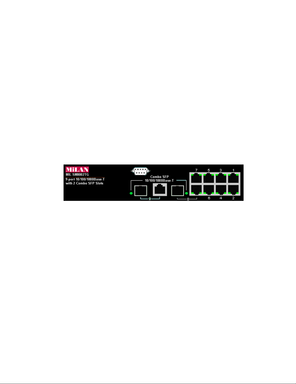
Front Panel
The Front Panel of the switch consist of 9x auto-sensing 10/100/1000Mbps Ethernet
RJ-45 ports (automatic MDI/MDIX), 2 SFP copper combo ports, and the LED indicators
are also located on the frond panel of the switch.
Front Panel of the switch
RJ-45 Ports (Auto MDI/MDIX): Nine 10/100/1000 auto- sensing for 10Base-T or
100Base-TX or 1000Base-T connections.
In general, MDI means connecting to another Hub or Switch while MDIX means
connecting to a workstation or PC. Therefore, Auto MDI/MDIX means that you can
connect to another Switch or workstation without changing non-crossover or
crossover cabling.
2 SFP/Giga copper combo port: 2 auto detect Giga port—UTP or fiber. Giga fiber is
the SFP module that is optional.
6
Page 15

LED Indicators
The following table provides descriptions of the LED statuses and meaning. They provide
a real-time indication of systematic operation status.
LED Status Description
Power
1000M
LNK / ACT
Green Power On
The port is operating at the speed of
Yellow
1000Mbps.
The port is operating at the speed of
Orange
100Mbps.
The port is operating at the speed of
Off
10Mbps or no device attached
The port is successfully connecting
Green
with the device.
The port is receiving or transmitting
Blinks
data.
Off No device attached.
The port is successfully connecting
Green
with the device.
LNK / ACT
The port is receiving or transmitting
Blinks
(SFP)
data.
Off No device attached.
7
Page 16
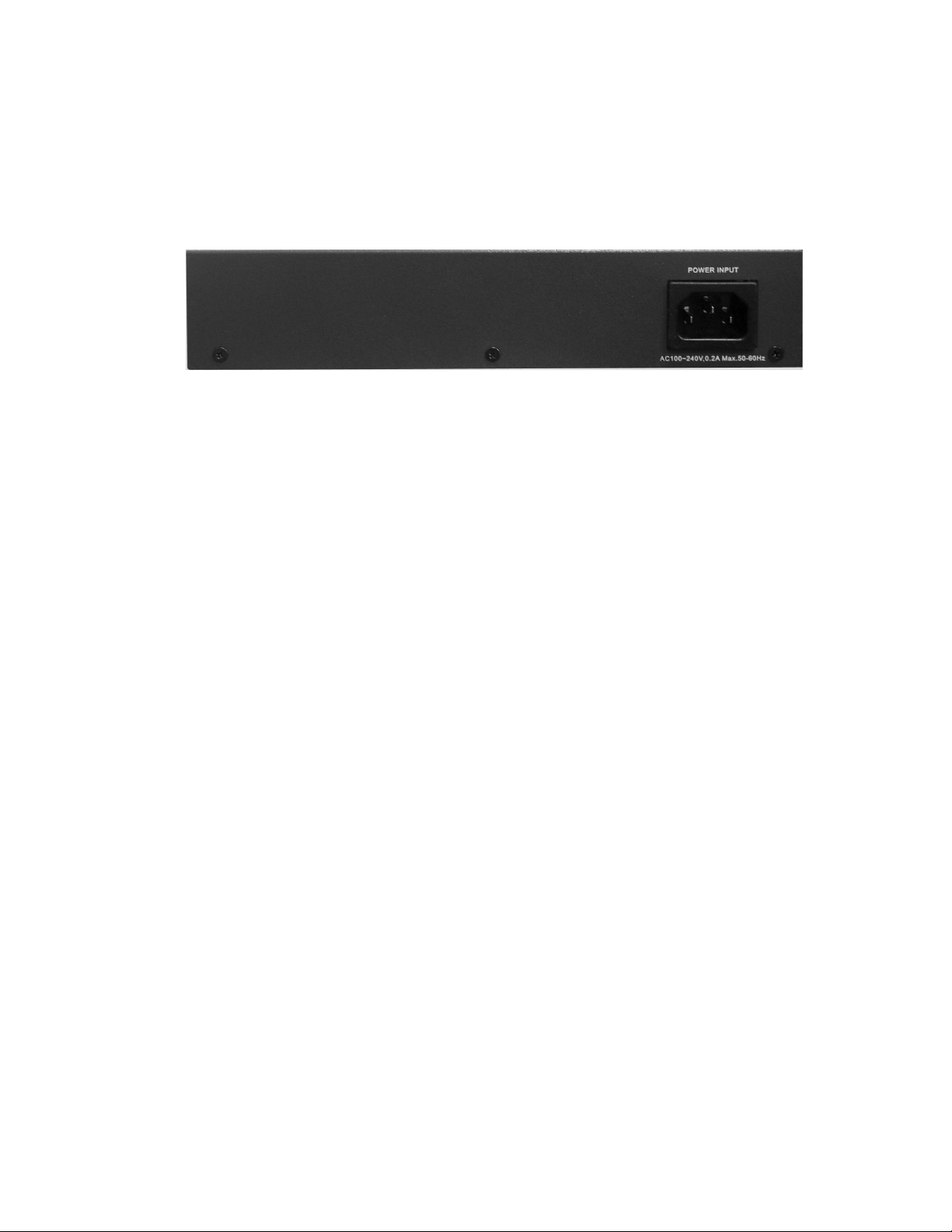
Rear Panel
The 3-pronged power plug are located at the Rear Panel of the switch as shown in figure.
The Switches will work with AC in the range 90-240V AC, 50-60Hz.
Rear Panel of the switch
Desktop Installation
Set the switch on a sufficiently large flat space with a power outlet nearby. The surface
where you put your Switch should be clean, smooth, level, and sturdy. Make sure there is
enough clearance around the Switch to allow attachment of cables, power cord and air
circulation.
Attaching Rubber Feet
1. Make sure mounting surface on the bottom of the Switch is grease and dust free.
2. Remove adhesive backing from your Rubber Feet.
3. Apply the Rubber Feet to each corner on the bottom of the Switch. These footpads
can prevent the Switch from shock/vibration.
Power On
Connect the power cord to the power socket on the rear panel of the Switch. The other
side of power cord connects to the power outlet. The internal power works with AC in the
voltage range 90-240VAC, frequency 50~60Hz. Check the power indicator on the front
panel to see if power is properly supplied.
8
Page 17
Network Application
Desktop Application
The switch is designed to be a desktop size switch that is an ideal solution for small
workgroup. The Switch can be used as a standalone switch to which personal computers,
server, printer server are directly connected to form small workgroup.
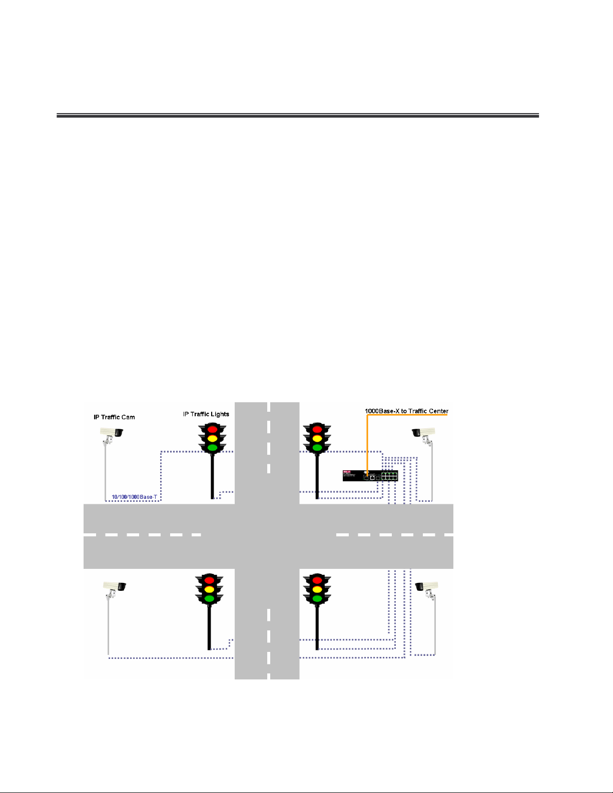
Indoor & Protected Outdoor Application
IP based technologies start dominating outdoor applications, that have been historically
reserved for serial connectivity. Gigabit switches gradually leave traditional LANs and
become a backbone for infrastructure connectivity and management. MIL-SM8002TG
switches can interconnect IP-based Traffic control lights, Traffic Cameras and message
boards.
9
Page 18

Console Management
Connecting to the Console Port
Use the supplied RS-232 cable to connect a terminal or PC to the console port. The
terminal or PC to be connected must support the terminal emulation program.
Connecting the switch to a terminal via RS-232 cable
Login in the Console Interface
When the connection between Switch and PC is ready, turn on the PC and run a terminal
emulation program or Hyper Terminal and configure its communication parameters to
match the following default characteristics of the console port:
Baud Rate: 9600 bps
Data Bits: 8
Parity: none
Stop Bit: 1
Flow control: None
10
Page 19
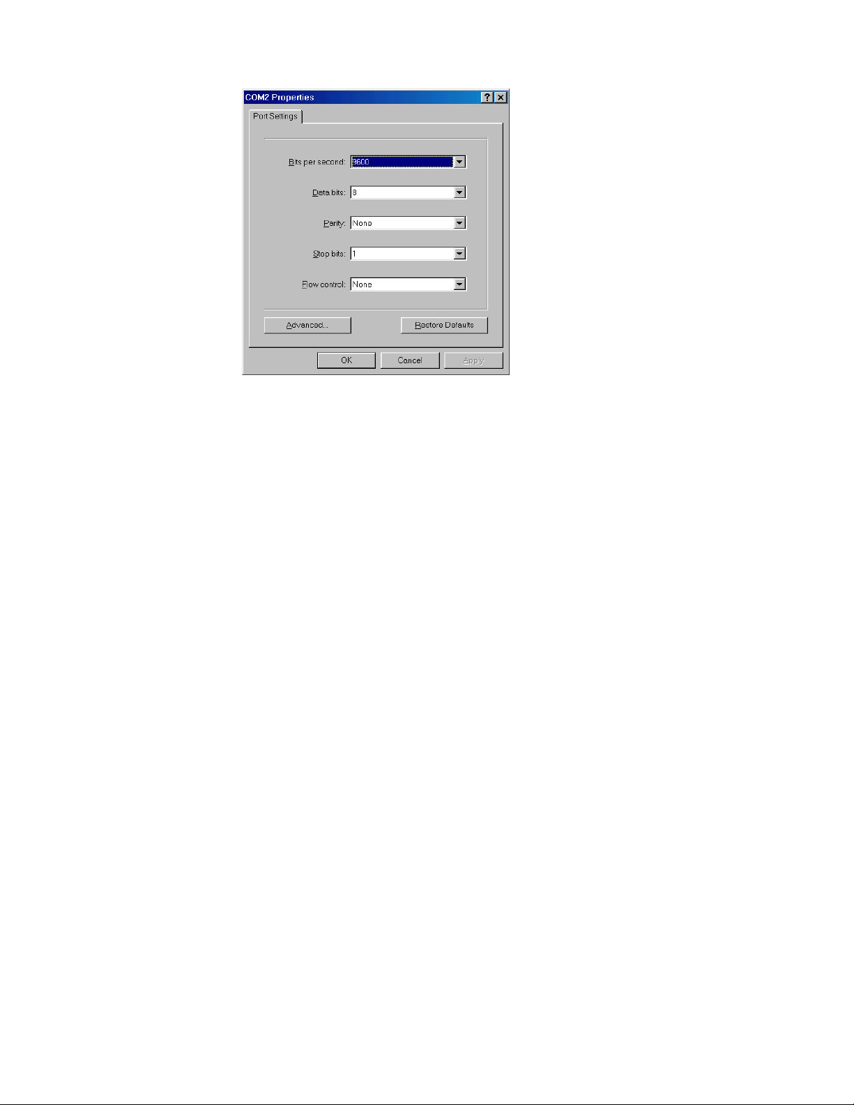
The settings of communication parameters
After finished the parameter settings, click “OK“. When the blank screen shows up, press
Enter key to bring out the login prompt. Key in the “root“(default value) for the both User
name and Password (use Enter key to switch), then press Enter key and the Main Menu
of console management appears. Please see below figure for login screen.
11
Page 20
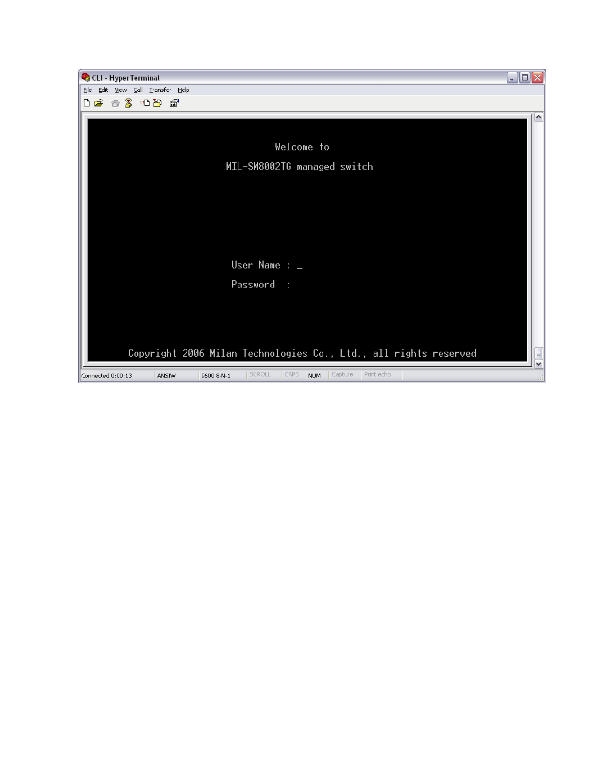
Console login interface
12
Page 21

CLI Management
The system supports two types of console management – CLI command and Menu
selection. After you login to the system, you will see a command prompt. To enter CLI
management interface, enter “enable” command. The following table lists the CLI
commands and description.
Commands Level
Modes Access Method Prompt Exit Method About This Mode1
The user commands available at
the user level are a subset of
User EXEC
Privileged
EXEC
Global Configuration
VLAN database
Begin a session with
your switch.
Enter the enable
command while in
user EXEC mode.
Enter the configure
command while in
privileged EXEC
mode.
Enter the vlan
database command
while in privileged
EXEC mode.
switch>
switch#
switch (config)#
switch (vlan)#
Enter logout or
those available at the privileged
level.
quit.
Use this mode to
• Perform basic tests.
• Display system information.
The privileged command is
advance mode
Enter disable to
Privileged this mode to
exit.
• Display advance function status
• Save configures
To exit to
Use this mode to configure
privileged EXEC
parameters that apply to your
mode, enter exit
switch as a whole.
or end
To exit to user
Use this mode to configure
EXEC mode,
VLAN-specific parameters.
enter exit.
Enter the interface
Interface
configuration
command (with a
specific interface)
while in global
switch
(config-if)#
13
To exit to global
Use this mode to configure
configuration
parameters for the switch and
mode, enter exit.
Ethernet ports.
To exist to
Page 22

command to set an
configuration mode privileged EXEC
mode, or end.
Commands Set List
System Commands Set
Commands Command Level Description Defaults Example
system name
[systemname]
system location
[system location]
system description
[systemdescription]
system contact
[systemcontact]
Global
configuration mode
Global
configuration mode
Global
configuration mode
Global
configuration mode
Set switch system name string
Set switch system location string
Set switch system description
string
Set switch system contact
window string
Switch (config)# system
name xxx
Switch (config)# system
location LA
Switch (config)# system
description xxx
Switch (config)# system
contact John
ip address
[ip-address]
[subnet-mask ]
[ gateway]
Use the ip address interface
configuration
Global
configuration mode
14
IP address for a switch. Use the
no form of this command to
remove an IP address or to
disable IP processing.
Switch (config)# ip
address 192.168.1.77
255.255.255.0
192.168.1.254
Page 23

(maximum
reload
default
username [user-name]
password [password]
Global
configuration mode
Global
configuration mode
Global
configuration mode
Global
configuration mode
Halt and perform a cold restart
Restore to default Switch (config)# Default
Changes a login username.
(maximum 10 words)
Specifies a password
10 words)
Switch (config)# reload
Switch (config)#
username xxxxxx
Switch (config)#
Password xxxxxx
Switch> show system
show system info User EXEC Show system information
show ip
Privileged
Show ip information
EXEC
info
Name: switch1
location: lab
Description: layer2 switch
Contact: somewhere
Serial NO: 1.00
Switch# show ip
Address ip: 192.168.1.77
Address subnet:
255.255.255.0
Address gateway:
192.168.1.254
15
Page 24

Use the show version user EXEC
command
information for
show accounting
Privileged
EXEC
show version User EXEC
Privileged
show terminal
EXEC
Show username & password
command to display version
information for the hardware and
firmware.
Use the show terminal
to display console
the switch
Switch# show accounting
Username: root
Password: root
Switch> show version
Firmware version: 1.0
Hardware version: 3.0
Kernel version: 1.10
Switch (config)# show
terminal
Baud rate (bits/sec):
9600
Data Bits: 8
Parity Check: none
Stop Bits: 1
Flow Control: none
Port Commands Set
Commands Command Level Description Defaults Example
interface [FastEthernet
/module Ethernet] [slot
id] [id]
Interface
configuration mode
Use the fast Ethernet interface
configuration command
Use the module Ethernet
interface configuration
command
Switch (config)# interface
fastEthernet 0/1
Switch (config)# interface
moduleEthernet 1/1
16
Page 25

duplex full
duplex [full | half| auto]
speed
[10 | 100 | 1000 | auto]
Interface
configuration mode
Interface
configuration mode
Use the duplex configuration
command to specify the duplex
mode of operation for Fast
Ethernet.
Use the duplex configuration
command to specify the duplex
mode of operation for module
Ethernet.
Use the speed configuration
command to specify the speed
mode of operation for Fast
Ethernet.
Auto
Auto
Auto
Switch (config)# interface
fastEthernet 0/1
Switch (config-if)#
Switch (config)# interface
moduleEthernet 1/1
Switch (config-if)# duplex full
Switch (config)# interface
fastEthernet 0/1
Switch (config-if)# speed 10
speed [10| 100 | 1000 |
auto]
Interface
configuration mode
Use the speed configuration
command to specify the speed
mode of operation for module
Ethernet.
(The 100Base-FX module only
supported for speed 100)
(The 1000Base-FX module
only supported for speed 1000
& auto)
17
Switch (config)# interface
fastEthernet 1/2
Switch (config-if)# speed
1000
Page 26

on
flowcontrol
on
on
Use the flow control
flowcontrol on or no
flowcontrol
security on or no
security
Interface
configuration mode
Interface
configuration mode
configuration command on
Ethernet ports to control traffic
rates during congestion.
Use the no form of this
command to disable security
the port.
Use the security configuration
command on Ethernet ports.
Use the no form of this
command to disable security
the port.
Switch (config)# interface
fastEthernet 0/1
On
Switch (config-if)#
on
Switch (config)# interface
fastEthernet 0/1
Disable
Switch (config-if)# security
on
Use the priority configuration
priority on [hi | low] or
no priority
Bandwidth [in | out]
[value]
18
Interface
configuration mode
Interface
configuration mode
command on Ethernet ports.
Use the no form of this
command to disable security
the port.
Set bandwidth in or out rate.
The value rage is (0~999), and
zero of the value is disable
(The module can’t be setting)
Switch (config)# interface
fastEthernet 0/1
Disable
Switch (config-if)# priority on
hi
Switch (config)# interface
fastEthernet 0/1
Disable
Switch (config-if)# bandwidth
in 50
Page 27

Use the state interface
State [Enable | Disable]
show interface
configuration
Interface
configuration mode
Interface
configuration mode
configuration command to
specify the state mode of
operation for Ethernet ports.
Use the disable form of this
command to disable the port.
show interface configuration
status
Switch (config)# interface
fastEthernet 0/1
Enable
Switch (config-if)# state
disable
Switch (config)# interface
fastEthernet 0/1
Switch (config-if)# show
interface configuration
show interface status
show interface
accounting
Interface
configuration mode
Interface
configuration mode
Switch (config)# interface
fastEthernet 0/1
show interface actual status
Switch (config-if)# show
interface status
Switch (config)# interface
fastEthernet 0/1
show interface statistic counter
Switch (config-if)# show
interface accounting
19
Page 28

Switch (config)# interface
show bandwidth
Trunk Commands Set
Commands Command Level Description Defaults Example
port group
[group-number]
[port-list] lacp [on | off]
workp [work ports]
no port group
[group-number] lacp [on
| off] workp [work ports]
Interface
configuration mode
Global
configuration mode
Display the bandwidth of the
values
Add trunking group.
Use the no form of this
Disable
command to delete trunking
group.
fastEthernet 0/1
Switch (config-if)# Show
bandwidth
LACP:
Switch (config)# port group 1
1-4
lacp on workp 2
Trunk without LACP:
Switch (config)# port group 1
1-4
lacp off workp 4
Switch # show group 1
Display trunk group
show group [group-ID]
port group
[group-number]
activityport [port-list]
20
Privileged EXEC
mode
Global
configuration mode
information. If there is no
group-number in put,
display all trunk groups.
Set trunking group port
active
Group Trunk.1:
Ports: 02 03 04
Priority: 0001
Lacp: Enable
Work ports: 0
Switch (config)# port group 3
activityport 2-4
Trunk.1 Lacp: Enable
Page 29

se the no form of this
show vlan [GroupName]
Check OK!
NEW: 2 4
Update finished!!
VLAN Commands Set
Commands Command Level Description Defaults Example
Vlan datatbase
vlanmode [disable|
portbase| 802.1q | gvrp]
vlan [Group Name]
grpid [Group ID] port
[Port Number]
no vlan Group Name]
[Group ID]
[GroupID] or show vlan
vlan [Group name] add
[port Number] [tagged |
untagged]
Privileged EXEC
mode
VLAN database
mode
VLAN database
mode
VLAN database
mode
VLAN database
mode
VLAN database
mode
To enter the VLAN
configuration interface
To set switch VLAN
mode .U
command to restore to
default.
Port Base VLAN
Add new Port Base VLAN
Delete port base VLAN
group
Show VLAN of Group Name
or Group ID information
Set the port of some port
group tagged or untagged
Switch# vlan database
Switch(vlan)#
Switch (vlan)# vlanmode
Disable
802.1q
Switch (vlan)# vlan v2 grpid 2
port 1-4
Switch (vlan)# no vlan v2 2
Switch (vlan)# Show vlan v2 2
Switch (vlan)# vlan v2 add 5
tagged
vlan [Group name]
delete [port Number]
vlan [Group name]
vlanid [Vlan ID] port
[port Number] tag
[port Number]
no vlan VLAN database Delete 802.1Q VLAN group Switch (vlan)# no vlan v2
VLAN database
mode
VLAN database
mode
Remove the port from it’s
port group.
802.1Q | 802.1Q with GVRP VLAN mode
Add new 802.1Q VLAN
[VLAN name]:
VLAN name
[VLAN ID]: 1 ~ 4094
[port ID]:
port members 1~9
21
Switch (vlan)# vlan v2 delete
5
Switch(vlan)# vlan v2 vlanid 2
port 1-4
tag 2-4
Page 30

[Group name] or [VLAN
ID]
vlan protocol [Group
name] [protocol value]
vlanid [VLAN ID] port
[portNumber] tag [port
Number]
mode Switch (vlan)# no vlan v2 2
Add protocol vlan
[Group name]: vlan group
name [protocol value] IP-ip ,
ARP-arp,
Appletalk_AARP-app_arp ,
Novell_IPX-ipx ,
Banyan_vines-banyan_c4,
Banyan_vines-banyan_c5,
Banyan_vines-banyan_ad,
VLAN database
mode
Decent_mop_01-decent_01,
Decent_mop_02-decent_02,
Decent_dpr-decent_dpr,
Decent_LAT-decent_lat,
Decent_LAVC-decent_larc,
IBM SNA-ibm, X.75
6510,6526
Switch (vlan)# vlan protocol
v3 ip vlanid 2 port 5-8 tag 6,8
vlanidrange
[VLANidrange]
VLAN database
mode
internet-x75, X.25
Layer3-x25
[VLAN ID]: 1 ~ 4094
[port Number]:
port Number 1~24
Set VLAN ID range
[1~255] range 0
[256~511] range 1
[512~767] range 2
[768~1023] range 3
[1024~1279] range 4
[1280~1535] range 5
[1536~1791] range 6
[1792~2047] range 7
[2048~2303] range 8
[2304~2559] range 9
[2560~2815] range 10
Switch (vlan)# vlanidrange 2
OLD: 0
NEW: 2
[2816~3071] range 11
[3072~3327] range 12
[3328~3583] range 13
22
Page 31

Remove the port from its port
VLAN protocol
[3584~3839] range 14
[3840~4094] range 15
[Groupname] add
[portNumber] [tagged |
untagged]
VLAN protocol
[Groupname] delete
[portNumber]
show vlan [Groupname]
[GroupID] or show vlan
show vlan protocol
port [port ID] pvid [port
VID] ingressfilter1 [on
| off] ingressfilter2 [on
| off]
VLAN database
mode
VLAN database
mode
VLAN database
mode
VLAN database
mode
VLAN database
mode
Set the port of some port
group tagged or untagged
group.
Show VLAN of Group Name
or VLAN ID information
vlanid: 1 ~ 4094
show protocol vlan
Protocol
ip
ipx
netbios
Set Port PVID and Ingress
Filter Rules1 & Ingress Filter
Rules2
Switch (vlan)# show vlan v2 2
Switch (vlan)# vlan protocol
v2 add 5 tagged
Switch (vlan)# vlan protocol
v2 delete 5
Switch (vlan)# show vlan
protocol
Switch (vlan)# port 2 pvid 2
ingressfilter1 off ingressfilter2
on
Switch (vlan)# show port 2
show port [port ID]
VLAN database
mode
Spanning Tree Commands Set
Commands Command Level Description Defaults Example
show spanning-tree User EXEC mode
show Port PVID and Ingress
Filter Rules1 & Ingress Filter
Rules2
Display a summary of the
spanning-tree states.
23
Port ID: 2
Port Vid: 2
Ingress 1 Filter: Disable
Ingress 2 Filter: Enable
Switch> show spanning-tree
System:
Priority: 32768
Max Age: 20
Hello Time: 2
Forward Delay: 15
Page 32

Priority: 32768
Mac Address: 004063800030
Root_Path_Cost: 0
Root Port: we are root
Max Age: 20
Hello Time: 2
Forward Delay: 15
Use the spanning-tree global
configuration command to
spanning-tree [on / off]
or no spanning-tree
spanning-tree priority
[number]
Global
configuration mode
Global
configuration mode
enable Spanning Tree
Protocol (STP). Use the no
form of the command to
restore to default
Use the spanning-tree
max-age global configuration
command to change the
priority.
Use the no form of this
command to return to the
default interval.
Disable
Switch (config)# spanning-tree
on
Switch (config)# spanning-tree
32768
priority 32767
Use the spanning-tree
max-age global configuration
command to change the
spanning-tree max-age
[seconds]
24
Global
configuration mode
interval between messages
the spanning tree receives
from the root switch. If a
switch does not receive a
bridge protocol
20 sec
Switch (config)# spanning-tree
max-age 15
Page 33

time
this command to return to the
data unit (BPDU) message
from the root switch within
this interval, it recomputes
the Spanning Tree Protocol
(STP) topology. Use the no
form of this command to
return to the default interval.
Use the spanning-tree
hello-time global
configuration command to
spanning-tree hello-
[seconds]
stp-path-cost [PortCost]
Global
configuration mode
Interface
configuration mode
specify the interval between
hello
bridge protocol data units
(BPDUs). Use the no form of
default interval.
Use the spanning-tree cost
interface configuration
command to set the path
cost for Spanning Tree
Protocol (STP) calculations.
In the event of a loop,
spanning tree considers the
path cost when selecting an
interface to place into the
forwarding state. Use the no
form of this command to
2 sec.
Switch (config)# spanning-tree
hello-time 3
10 Mbps
Switch (config)# interface
– 100
fastEthernet 0/2
Switch (config-if)#
100 Mbps
stp-path-cost 20
– 10
spanning-tree
forward-time [seconds]
Global
configuration mode
return to the default value.
Use the spanning-tree
forward-time global
configuration command to
set the forwarding-time for
the specified spanning-tree
instances. The forwarding
time determines how long
each of the listening and
25
15 sec.
Switch (config)# spanning-tree
forward-time 20
Page 34

this command to return to the
learning states last before
the port begins forwarding.
Use the no form of this
command to return to the
default value.
Use the spanning-tree
port-priority interface
configuration command to
stp-path-priority [Port
Priority]
QOS Commands Set
Commands Command Level Description Defaults Example
qos storm-control
[5|10|15|20|25| off (%)]
or no storm-control
Interface
configuration mode
Global
configuration mode
configure a port priority that
is used when two switches
tie for position as the root
switch. Use the no form of
default value.
Enable/Disable broadcast
storm control. Use the no form
of this command to restore to
default.
128
OFF
Switch (config)# interface
fastEthernet 0/2
Switch (config-if)#
stp-path-priority 127
Switch (config)# qos
storm-control 5
qos
low-priority-delay-bound
[on|off] [sec.] or no qos
low-priority-delay-bound
qos level [priority]
enable
26
Global
configuration mode
Global
configuration mode
Enable/Disable low priority
delay board.
Use the no form of this
command to restore to default.
[Priority] 0~7
OFF
0~3 LOW
4~7 HI
Switch (config)# qos
low-priority-delay-bound on
1
Switch (config)# qos level
2,3 enable
Page 35

qos queuepolicy [Policy]
no qos level [priority]
hi [Priority] low [Priority]
Global
configuration mode
Global
configuration mode
[Priority] 0~7
[Policy]:fcfs: first in and first out
wrr: wnine round robin
sp: all high before low.
[Priority] Hi:1~7 Low:1
0~3 LOW
4~7 HI
WRR
Hi 2
Low 1
Switch (config)# no qos
level 0-7
WRR:
Switch (config)# qos
queuepolicy wrr hi 7 low 1
First Come First Served:
Switch (config)# qos
queuepolicy fcfs
All High before Low:
Switch (config)# qos
queuepolicy sp
qos bridge-delay-bound
[number] .
no qos
bridge-delay-bound
show qos storm-control
Global
configuration mode
Global
configuration mode
Set qos bridge delay bound
Use the no form of this
command to restore to default.
Show broadcast storm control.
27
OFF
Switch (config)# qos
bridge-delay-bound 1
Switch (config)# show qos
storm-control
QOS storm control mode:
ENABLE
Page 36

Switch (config)# show qos
show qos
low-priority-delay-bound
show qos policy
show qos
bridge-delay-bound
Privileged EXEC
mode
Privileged EXEC
mode
Privileged EXEC
mode
Show low priority delay board.
Show qos policy
Show bridge delay bound
low-priority-delay-bound
Qos low priority delay
bound: 1
Switch (config)# show qos
policy
Qos Mode: WRR
Switch (config)# show qos
bridge-delay-bound
bridge-delay-bound 5
IGMP Commands Set
Commands Command Level Description Defaults Example
igmp [on | off]
Igmp-query
[auto |enable | disable]
show ip igmp profile
Global
configuration
mode
Global
configuration
mode
Privileged EXEC
mode
Enable /Disable IGMP
Off Switch (config)# igmp on
snooping function
Modify IGMP query mode Disable
Displays the details of an IGMP
profile entry.
Switch (config)# Igmp-query
enable
Switch# show ip igmp profile
IP VID
Port 224.1.1.1 10 1,2,6
28
Page 37

table
configuration command to set
time interval. The aging
table table
remove static entries from the
Mac / Filter Table Commands Set
Commands Command Level Description Defaults Example
(Enable)
Switch (config)#
mac-address-table
aging-time [on | off]
mac-address-table
aging-time [sec.]
or no mac-address-
aging-time
mac-address-
[static | filter] hwaddr
[MAC address] vlanid
[VLAN-ID]
Global
configuration mode
Interface
configuration mode
Use the mac-address-table
aging-time global
the length of time that a
dynamic entry remains in the
MAC address table after the
entry is used or updated.
Use the no form of this
command to use the default
aging-
time applies to all VLANs.
Use the mac-address-table
static to add static | filter
addresses to the MAC
address table. Use the no
form of this command to
mac-address-table aging-time
on
Switch (config)#
mac-address-table aging-time
333
300 secs
(Disable)
Switch (config)#
mac-address-table aging-time
off
Or
Switch(config)# no
mac-address-table aging-time
Switch (config)# interface
fastEthernet 0/2
Switch (config-if)#
N/A
mac-address-table static
hwaddr 004063112233 vlanid
no mac-address-table
[static | filter] hwaddr
[MAC address] vlanid
[VLAN-ID]
Interface
configuration mode
MAC address table.
Use the no
mac-address-table privileged
EXEC command to delete
entries from the MAC
address table.
29
10
Switch (config)# interface
fastEthernet 0/2
Switch (config-if)# no
mac-address-table static
hwaddr 004063112233 vlanid
10
Page 38

show
mac-address-table
[static | filter]
show
mac-address-table
aging-time
SNMP Commands Set
Commands Command Level Description Defaults Example
snmp system-name
[SystemName]
Privileged EXEC
mode
Privileged EXEC
mode
Global
configuration mode
Use the show
mac-address-table user
EXEC command to display
the MAC address table.
Use the show
mac-address-table user
EXEC command to display
the MAC address table.
Set Snmp agent system
name
Switch (config)# show
mac-address-table static
Switch (config)# show
mac-address-table aging-time
300
MAC Address aging-time: 300
Switch (config)# snmp
N/A
system-name l2switch
snmp system-location
[SystemLocation]
snmp system-contact
[SystemContact]
snmp community-strings
[Community] right [RO |
RW]
Or
no snmp
community-strings
[Community]
30
Global
configuration mode
Global
configuration mode
Global
configuration mode
Set Snmp agent system
location
Set Snmp agent system
contact
Add snmp community
string. Use the no form of
this command to remove
the specified community.
N/A
N/A
PUBLIC RO
Switch (config)# snmp
system-location lab
Switch (config)# snmp
system-contact where
Switch (config)# snmp
community-strings public right
RW
Page 39

command to enable Switch
command to return the port
privileged EXEC command
Port 1 Rx: Monitor Port 1 Rx:
t 3 Rx:
Port 8 Rx: Analysis Port 8 Tx:
Port Mirroring Commands Set
Commands Command Level Description Defaults Example
Use the port monitor
port monitor
[RX|TX|Both |Disable]
PortList
Or
no port monitor
show port monitor
Interface
configuration mode
Interface
configuration mode
interface configuration
Port Analyzer (SPAN) port
monitoring on a port. Use
the no form of this
to its default value.
Use the show port monitor
to display the ports for
which Switched Port
Analyzer (SPAN) port
Switch (config)# Interface
fastEthernet 0/8
N/A
Switch (config-if)# port monitor
both 3
Switch (config-if)# show port
monitor
State: ENABLE
AnalysisPortId: 8
Monitor
Port 2 Rx: Port 2 Rx:
Port 3 Rx: Monitor Por
Monitor
Port 4 Rx: Port 4 Rx:
monitoring is enabled.
Port 5 Rx: Port 5 Rx:
Port 6 Rx: Port 6 Rx:
Port 7 Rx: Port 7 Rx:
Analysis
Port 9 Rx: Port 9 Rx:
31
Page 40

Stacking Commands Set
Commands
show stackinglist User EXEC Show IP stacking List
show stackinginfo
[MAC address]
stacking [MAC
address]
Command
Description Defaults Example
Level
Show the stack
User EXEC
information
Change to stacking
User EXEC
mode
Switch>show stackinglist
MAC = 00:22:33:44:55:66 [Master]
No Slave!
Switch>show stackinginfo
00.22.33.44.55.66
GroupID: 3000
Stacking Mode: Disable
System Information: test
Switch>stacking 00.22.33.44.55.66
Switch(stacking-00.22.33.44.55.66)#
Set the stack ID and
set idmode [ID]
Stacking Mode
[mode]
set information
Stacking Mode
[name]
32
mode
ID range: 0~65535
Mode: 0 = Disable, 1 =
Master, 2 = Slave
Set the information of
the Stack
Switch(stacking-00.22.33.44.55.66)#
set idmode 3000 0
Setting GroupID: 3000, stacking Mode
= Disable
Switch(stacking-00.22.33.44.55.66)#
set information test
Setting System Information: test
Page 41

Use the no form of this command to
d to
802.1x Commands Set
Commands
Command
Level
show 8021x User EXEC mode
Global
8021x [on | off]
configuration mode
8021x system radiusip
[RadiusServerIP]
Global
Or
configuration mode
no 8021x system
Description Defaults Example
Display a summary of the 802.1x
properties and also the port sates.
Use the 802.1x global configuration
command to enable 802.1x
protocols. Use the no form of the
command to restore to default
Use the 802.1x system radius IP
global configuration command to
change the radius server IP.
Switch> show 8021x
Disable Switch (config)# 8021x on
Switch (config)# 8021x
system radiusip
192.168.1.254
radiusip
8021x system sharekey
[Sharekey]
Global
or
configuration mode
no 8021x system
sharekey
8021x misc quietperiod Global Use the 802.1x misc quiet period Switch (config)# 8021x
return to the default interval.
Use the 802.1x system sharekey
global configuration command to
change the shared key value.
Use the no form of this comman
return to the default interval.
Switch (config)# 8021x
system sharekey 123456
33
Page 42

Use the no form of this command to
8021x misc supptimeout
the specified port is
[quietperiod value]
Or
no 8021x misc
quietperiod
8021x misc txperiod
[TXPeriod value]
Or
no 8021x txperiod
[SEC]
Or
no 8021x supptimeout
8021x misc
servertimeout [SEC]
Or
no 8021x servertimeout
configuration mode global configuration command to
specify the quiet period value of the
switch.
return to the default interval.
Use the 802.1x misc TX period
global configuration command to
Global
set the TX period.
configuration mode
Use the no form of this command
to return to the default value.
Set the period of time the switch
Global
wait for a supplicant response to
configuration mode
an EAP request.
Set the period of time the switch
Global
wait for a server response to an
configuration mode
authentication request.
misc quietperiod 10
Switch (config)# 8021x
misc txperiod 5
Switch(config)# 8021x
misc supptimeout 30
Switch(config)# 8021x
misc servertimeout 50
8021x misc maxrequest
[Number]
Or
no 8021x maxrequest
8021x misc
reauthperiod [SEC]
Or
no 8021x reauthperiod
8021x prostate [reject |
accept | authorize |
disable]
Global
configuration mode
Global
configuration mode
Interface
configuration
mode
Set the number of authentication
that must time-out before
authentication fails and the
authentication session ends.
Set the period of time after which
clients connected must be
re-authenticated..
Use the 802.1x port state interface
configuration command to set the
state of the selected port.
Reject: the specified port is
required to be held in the
unauthorized state.
Accept: the specified port is
required to be held in the
Authorized state.
Switch(config)# 8021x
misc maxrequest 2
Switch(config)# 8021x
misc reauthperiod 20
Switch (config)# interface
fastethernet 0/3
Switch (config-if)# 8021x
portstate accept
34
Authorized:
Page 43

TFTP Commands Set
set to the Authorized or
Unauthorized state in
accordance with the outcome of
an authentication exchange
between the Supplicant and the
authentication server.
Disable: The specified port is
required to be held in the
Authorized state.
Commands
copy flash:config.text
tftp [TFTP IP address]
[file name]
tftp:config.text flash
[TFTP IP address] [file
name]
tftp:firmware flash
[TFTP IP address]
[file name]
Command
Level
Global configuration
mode
Global configuration
mode
Global configuration
mode
Description Defaults Example
Switch (config)# copy
Backup configure file
command
Restore configure file
command
Update firmware command
flash:config.text tftp
>192.168.1.1
>backup.dat
Switch(config)#
Tftp:config.text flash
>192.168.1.1
>restore.dat
Switch (config)# Tftp:firmware
flash
>192.168.1.1
>image.bin
35
Page 44

Main Menu
There are five selections as follow.
System Configuration: Configure system information, IP, DHCP, login security,
event logs and firmware update.
Port Configuration: Display port statistics. Configure the port control, trunk, rate
limiting and mirroring.
Protocol Configuration: Configure VLAN, RST, SNMP, QoS, SNTP, IGMP, and
Super Ring function.
Security Configuration: Configure 802.1X, IP, and Port security function.
Load Factory Default: Reset switch to default configuration.
Save All Configuration: Save the configuration that user had made in the switch
system.
Reboot the Device: Reboot the switch system without reset to the default value.
Logout: Exit the menu line program.
36
Page 45

Main menu line interface
Control Key description:
The control keys provided in all menus:
Tab: Move the vernier to next item.
Backspace: Move the vernier to previous item.
Enter: Select item.
Space: Toggle selected item to next configure or change the value.
Esc: to exit the current action mode.
System Configuration
In System Configuration, you can configure system event log, SMTP, system description,
IP, DHCP, login security and firmware update. You can press the “Tab” or “Backspace” to
37
Page 46

choose the item, and press “Enter” key to select the item.
Status and Counters main configuration interface
System Information
You can configure the name, description, location, contact of the system. Also, you can
view the version of firmware, hardware, kernel and MAC address.
1. Name: the name of device.
2. Description: the name of device type.
3. Location: where the device is located.
4. Contact: the contact person or information.
5. Firmware Version: the switch’s firmware version.
6. Hardware Version: the switch’s Hardware version.
7. Kernel Version: the system kernel software version.
38
Page 47

8. MAC Address: The unique hardware address assigned by manufacturer.
System Description interface
IP Configuration
You can configure the IP for the switch. The system has the default IP address. You can
re-configure or use the default value.
1. DHCP: disable or enable the DHCP client function. When DHCP function is enabling,
you don’t need to assign the IP address and subnet mask. The system will be
assigned the IP address from the local DHCP server.
2. IP Address: assign the switch IP address. The default IP is 192.168.1.77
3. Subnet Mask: assign the switch IP subnet mask.
4. Gateway: assign the switch gateway. The default value is 192.168.1.254
5. DNS1: Short for Domain Name Server an
Internet
service that translates
domain
39
Page 48

name
remember.
name
address. For example, the
192.168.1.1.
6. DNS2: The backup for DNS1. When the DNS1 cannot function, the DNS2 can replace
DNS1 immediately.
7. Select <Save> action to save the configuration.
[NOTE] Always restart the switch after finished the setup.
into IP addresses. Because
The Internet
, therefore, a
is based on
DNS service
domain name
domain name
IP address
must translate the name into the corresponding IP
are alphabetic, they're easier to
. Every time you use a
www.net.com might translate to
domain
IP Configuration interface
40
Page 49

DHCP Configuration
It short for Dynamic Host Configuration Protocol that is a protocol for assigning dynamic
IP addresses to devices on a network. With dynamic addressing, a device can have a
different IP address every time it connects to the network. In some systems, the device's
IP address can even change while it is still connected. DHCP also supports a mix of static
and dynamic IP addresses. Dynamic addressing simplifies network administration
because the software keeps track of IP addresses rather than requiring an administrator
to manage the task. This means that a new computer can be added to a network without
the hassle of manually assigning it a unique IP address.
DHCP Configuration interface
DHCP Server Configuration
41
Page 50

The system provides the DHCP server function. Enable the DHCP server function, the
switch system will be a DHCP server.
DHCP Server: Enable or Disable the DHCP Server function. Enable – the switch will
be the DHCP server on your local network.
Low IP Address: the dynamic IP assign range. Low IP address is the beginning of
the dynamic IP assigns range. For example: dynamic IP assign range is from
192.169.1.0 ~ 192.168.1.30. 192.168.1.0 will be the Low IP address.
High IP Address: the dynamic IP assign range. High IP address is the end of the
dynamic IP assigns range. For example: dynamic IP assign range is from
192.169.1.0 ~ 192.168.1.30. 192.168.1.30 will be the High IP address.
Subnet Mask: the dynamic IP assign range subnet mask.
Gateway: the gateway in your network.
DNS: Domain Name Server IP Address in your network.
Lease Time (sec): It is the time period that system will reset the dynamic IP
assignment to ensure the dynamic IP will not been occupied for a long time or the
server doesn’t know that the dynamic IP is idle.
42
Page 51

DHCP Server Configuration interface
DHCP Client Entries
When the DHCP server function is active, the system will collect the DHCP client
information and display in here.
43
Page 52

DHCP Client Entries interface
Port and IP Bindings
You can assign the specific IP address that is the IP in dynamic IP assign range to the
specific port. When the device is connecting to the port and asks for dynamic IP assigning,
the system will assign the IP address that has been assigned before to the connected
device.
44
Page 53

Port and IP Bindings interface
Firmware Update
It provides user to update firmware or restore EEPROM value or backup current EEPROM
value.
1. Start the TFTP server, and copy new firmware version image file to the TFTP server.
2. TFTP Server IP: type the IP of TFTP server.
3. Function: the system provides three functions – update, restore, and backup.
Update: update the firmware.
Restore: restore EEPROM value, which saved in TFTP server, from TFTP
server.
Backup: save current EEPROM value to TFTP server as backup. The backup
file can be restore from TFTP server when you need.
45
Page 54

4. File Name: type the image file name.
5. Press “ESC” to back to action line.
6. “Save” the configuration.
Firmware Update interface
System Event Log
You can configure the switch as the system log client that can view the system log
information that from the system log server that you have assigned.
46
Page 55

System Log Configuration interface
System Log Configuration
Configuring the system event mode that want to be collected and system log server
IP.
1. Collection Mode: select the system log mode – client only, server only, or both S/C.
2. System Log Server IP Address: assigned the system log server IP.
47
Page 56

System Log Configuration interface
Event Configuration
You can select the system log and SMTP events. When selected events occur, the system
will send out the log information or alert.
Device cold start: when the device executes cold start action, the system will
produce a log event.
Device warm start: when the device executes warm start, the system will produce a
log event.
Authentication Failure: when the SNMP authentication fails, the system will
produce a log event.
Super Ring topology change: when the Super ring topology has changed, the
system will produce a log event.
48
Page 57

Email Alert Configuration
When the specific events occur, the system will send the alert to the email account that is
assigned by user.
49
Page 58

Email Alert Configuration interface
SMTP Configuration
You can set up the mail server IP, mail account, and account password.
1. Email Alert: enable or disable the email alert function.
2. SMTP Server IP: set up the mail server IP address.
3. Authentication: mark the check box to enable and configure the email account and
password for authentication.
4. Mail Account: set up the email account to receive the alert. Ex:
johnadmin@123.com. The email account must exist on the mail server, which you
had set up in SMTP Server IP Address column.
5. Password: The email account password.
6. Confirm Password: reconfirm the password.
50
Page 59

SMTP Configuration interface
Recipient’s email Configuration
Assign the forwarded email account for receiving the event alert.
Rcpt E-mail Address 1 ~ 6: you can assign up to 6 e-mail accounts also to receive
the alert.
51
Page 60

Recipient’s email Configuration interface
Security Manager
You can change the console and web management login user name and password for the
security issue.
1. User Name: Enter the new user name. The default user name is “root”.
2. New Password: enter the new password. The default password is “root”
3. Confirm Password: reenter the new password for confirmation.
52
Page 61

Security Manager interface
53
Page 62

Port Configuration
In this section, you can view port counter information; configure port control, mirroring,
trunk, and rate limiting.
Port Configuration main interface
Port Counters
It displays the current port counter information. Select the <Refresh>action to get newest
port counter information. Select the <Clear> action to set the port counter information
back to 0.
54
Page 63

Port Counter interface
Port Control Configuration
You can set up every port status.
1. Use “Tab” key to move between items.
2. Port: select the port that wants to be configured.
3. State: Current port status. The port can be set to disable or enable mode. If the port
setting is disable then will not receive or transmit any packet.
4. Neg: set auto negotiation status of port.
5. Speed: set the port link speed.
6. Duplex: set full-duplex or half-duplex mode of the port.
7. Flow Control: enable or disable Flow control function (Flow control is for full duplex
link mode).
8. Select the <Save>.
55
Page 64

9. To view the State of Ports, select <Refresh> to get the current ports state
information.
Port Control Configuration interface
Trunk Configuration
The Link Aggregation Control Protocol (LACP) provides a standardized means for
exchanging information between Partner Systems on a link to allow their Link Aggregation
Control instances to reach agreement on the identity of the Link Aggregation Group to
which the link belongs, move the link to that Link Aggregation Group, and enable its
transmission and reception functions in an orderly manner. Link aggregation lets you
group up to nine consecutive ports into a single dedicated connection. This feature can
expand bandwidth to a device on the network. LACP operation requires full-duplex
56
Page 65

mode, more detail information refers to IEEE 802.3ad.
Aggregator setting
1. System Priority: a value used to identify the active LACP. The switch with the lowest
value has the highest priority and is selected as the active LACP.
2. LACP Configuration: If enable, the group is LACP static trunk group. If disable, the
group is local static trunk group. All ports support LACP dynamic trunk group. If
connecting to the device that also supports LACP, the LACP dynamic trunk group will
be created automatically.
Trunk Group: there are three-trunk group – trunk 1, 2, and 3. You can select the
trunk group and enable the LACP or disable it.
Work ports: select a work port number for the trunk group. The LACP static
trunk group work port number cannot be 0.
Port Configuration: to assign the port to the trunk group.
3. Select the ports to join the trunk group.
4. Select the <Save> to save the configuration.
5. You can view the setting information in summary frame.
57
Page 66

Trunk Configuration — Aggregator Setting interface
Aggregator Information
When you had setup the LACP aggregator, you will see relate information in here.
58
Page 67

Trunk Configuration – Aggregator Information interface
State Activity
When you had setup the LACP aggregator, you can configure port state activity. You can
change the port state activity to Active or Passive.
1. Active: The port automatically sends LACP protocol packets.
2. Passive: The port does not automatically send LACP protocol packets, and responds
only if it receives LACP protocol packets from the opposite device.
[NOTE]
a. A link having either two active LACP ports or one active port can perform dynamic
LACP trunking.
b. A link has two passive LACP ports will not perform dynamic LACP trunking
because both ports are waiting for and LACP protocol packet from the opposite
device.
59
Page 68

c. If you are active LACP’s actor, when you are select trunking port, the active
status will be created automatically.
Trunk Configuration State Activity
Port Mirroring Configuration
The port mirroring is a method for monitor traffic of switched networks. The specific port
can monitor traffic through the mirror ports. The monitored ports in or out traffic will be
duplicated into monitoring port.
1. Analysis Port (TX): It’s mean mirror port can be used to see all monitor port traffic.
You can connect mirror port to LAN analyzer or Netxray.
2. Analysis Port (RX): Set the destination port of mirroring packet. All of the packets of
mirroring port will be duplicated and sent to Analysis port.
60
Page 69

3. Source Port (TX/RX): select the monitor mode of each port. You can choose which
port wants to monitor in only one mirror mode.
RX: RX packet only
TX: TX packet only
Both: RX and TX packet
Port Mirroring interface
Rate Limiting
You can set up every port’s bandwidth rate and packet limitation type.
Ingress Limit Packet type: select the packet type that want to filter. The packet
types have all type packet, broadcast/multicast/unknown unicast packet,
broadcast/multicast packet, and broadcast packet only. The
61
Page 70

broadcast/multicast/unknown unicast packet, broadcast/multicast packet, and
broadcast packet only are only for ingress packet. The egress rate only supports all
type packet.
All the ports support port ingress and egress rate control. For example, assume port 1
is 10Mbps, users can set it’s effective egress rate is 1Mbps, ingress rate is 500Kbps.
The switch performs the ingress rate by packet counter to meet the specified rate.
Ingress: enter the port effective ingress rate. The default value is “0”.
Egress: enter the port effective ingress rate. The default value is “0”.
Rate Limiting interface
62
Page 71

Protocol Configuration
In this section, you can configure VLAN, RST, SNMP, SNTP, QoS, IGMP, and Super ring.
Protocol Configuration interface
VLAN Configuration
The VLAN Configuration provides two VLAN modes – Port Base and 802.1Q. You need to
select the VLAN mode for the VLAN detail configuration. Use Space key to switch the
VLAN mode selection. After select the VLAN mode, save the selection. Press ESC key to
exit the VLAN Mode Selection interface.
63
Page 72

VLAN Mode Selection interface
Port Base VLAN Configure
Add VLAN group, remove VLAN group, and view the VLAN group list. Use Tab key to
move between the configure items.
64
Page 73

Group Add
1. Group Name: Type a name for the new VLAN, ex: VLAN01.
2. VID: Type the VLAN group ID. The group ID rang is from 1 to 4094.
a. Member Ports: Press”Space” key to change the port status. Mark the port to be
the member..
3. Select <Save> to save the configuration.
4. Press “ESC” key to go back action menu line.
65
Page 74

Group Add interface
Group Remove
You can remove unwanted VLAN group. Enter the group VID and select Save.
66
Page 75

Group Remove interface
Group List
Display the all VLAN groups’ information.
67
Page 76

Group List interface
802.1Q VLAN Configure
You configure GVRP setting, VLAN by port, and edit VLAN group.
68
Page 77

802.1Q VLAN Configuration interface
GVRP Setting
GVRP (Generic Attribute Registration Protocol) is an application defined in the IEEE
802.1Q standard that allows for the control of VLANs. Use Space key to change the
GVRP setting – Disable or Enable. And then, select the Save to apply the setting.
69
Page 78

GVRP Setting interface
Configure VLAN by Port
1. Select the port that wants to configure by using Spec key. Submit to get the port
current setting.
2. Link Type: there are 3 link types.
3. Untagged VID: assign the untagged frame VID.
4. Tagged VID: assign the tagged frame VID.
5. Save the configuration.
70
Page 79

Configure VLAN by Port interface
VLAN List
Enable or disable the VLAN group.
1. Group Name: you can rename the group name.
2. On/Del: On is active the VLAN group. Del is removing the VLAN group.
3. After editing, Apply the change.
71
Page 80

Edit VLAN Group interface
Rapid Spanning Tree
The Rapid Spanning Tree Protocol (RSTP) is an evolution of the Spanning Tree Protocol
and provides for faster spanning tree convergence after a topology change. The system
also supports STP and the system will auto detect the connected device that is running
STP or RSTP protocol.
72
Page 81

Rapid Spanning Tree interface
RSTP System Configuration
1. You can view spanning tree information about the Root Bridge.
2. You can modify RSTP state. After modification,
RSTP mode: you must enable or disable RSTP function before configure the
related parameters.
Priority (0-61440): a value used to identify the root bridge. The bridge with the
lowest value has the highest priority and is selected as the root. If you change
the value, you must reboot the switch assign path priority number. The value
must be multiple of 4096 according to the protocol standard rule.
Max Age (6-40): the number of seconds a bridge waits without receiving
the configuration.
save
Spanning-tree Protocol configuration messages before attempting a
reconfiguration. Enter a value between 6 through 40.
73
Page 82

Hello Time (1-10): the time that controls switch sends out the BPDU packet to
check RSTP current status. Enter a value between 1 through 10.
Forward Delay Time (4-30): the number of seconds a port waits before
changing from its Rapid Spanning-Tree Protocol learning and listening states to
the forwarding state. Enter a value between 4 through 30.
[NOTE] Follow the rule to configure the MAX Age, Hello Time, and Forward
Delay Time.
2 x (Forward Delay Time value –1) > = Max Age value >= 2 x (Hello Time
value +1)
RSTP System Configuration interface
RSTP Per Port Configuration
74
Page 83

You can configure path cost and priority of every port.
1. Select the port in Port column.
2. Path Cost: The cost of the path to the other bridge from this transmitting bridge at the
specified port. Enter a number 1 through 200000000.
3. Priority: Decide which port should be blocked by priority in LAN. Enter a number 0
through 240. The value of priority must be the multiple of 16.
4. P2P: Some of the rapid state transactions that are possible within RSTP are
dependent upon whether the port concerned can only be connected to exactly one
other bridge (i.e. it is served by a point-to-point LAN segment), or can be connected to
two or more bridges (i.e. it is served by a shared medium LAN segment). This function
allows the P2P status of the link to be manipulated administratively. True is P2P
enabling. False is P2P disabling.
5. Edge: The port directly connected to end stations cannot create bridging loop in the
network. To configure the port as an edge port, set the port to “True” status.
6. Neighbor: The port includes the STP mathematic calculation. True is not including
STP mathematic calculation. False is including the STP mathematic calculation.
7.
Apply
the setting.
75
Page 84

RSTP Per Port Configuration interface
SNMP Configuration
Simple Network Management Protocol (SNMP) is the protocol developed to manage
nodes (servers, workstations, routers, switches and hubs etc.) on an IP network. SNMP
enables network administrators to manage network performance, find and solve network
problems, and plan for network growth. Network management systems learn of problems
by receiving traps or change notices from network devices implementing SNMP.
76
Page 85

SNMP Configuration interface
System Options
Enter the system name, contact, and location information.
1. Name: assign a name for the switch.
2. Contact: Type the name of contact person or organization.
3. Location: Type the location of the switch.
4. Agent Mode: Select the SNMP version that you want to use it.
5. <Save> to save configure value.
77
Page 86

SNMP System Options interface
Community Strings
You can change the default community string that public and private attribute and define
two more set community string.
1. Community Name: It uses for authenticating the manager to allow access the agent.
Type the name of community strings. The Public and Private Community string
cannot be changed the name.
2. Attribute: enable the access rights is read only or read/write or string removed.
Read only: Read only, enables requests accompanied by this string to display
MIB-object information.
Read/Write: Read write, enables requests accompanied by this string to display
MIB-object information and to set MIB objects.
String Removed: this community string is disabling.
78
Page 87

3. Save the configuration.
Add Community Strings interface
Trap Managers
A trap manager is a management station that receives traps, the system alerts generated
by the switch. If no trap manager is defined, no traps will issue. Create a trap manager by
entering the IP address of the station and a community string. To define management
stations as trap manager and enter SNMP community strings and selects the SNMP
version.
1. Trap Manager IP: enter the IP address of trap manager.
2. Community Name: enter the community string.
3. Ver.: select the SNMP version type – v 1 or v2.
4. <Save> to save all configure
79
Page 88

5. To disable the trap manager, please delete the trap manager IP, community string
and version. And then, save to change.
SNMP V 3 Configuration
Configure the SNMP V3 function.
Trap Managers interface
80
Page 89

SNMP V3 configuration interface
Context Table
Configure SNMP v3 context table. Assign the context name of context table.
81
Page 90

SNMP v3_Context Table interface
User Table
Configure SNMP v3 user table..
1. User Name: set up the user name.
2. Auth Password: set up the authentication password.
3. Priv Password: set up the private password.
4. <Save> to save all configure
82
Page 91

SNMP v3_User Table interface
Group Table
Configure SNMP v3 group table.
1. User Name: assign the user name that you have set up in user table.
2. Group Name: set up the group name.
3. <Save> to save all configure
83
Page 92

SNMP v3_Group Table interface
Access Table
Configure SNMP v3 access table.
84
Page 93

SNMP v3_AccessTable interface
Add Table
Add the access table.
1. Context: set up the context name.
2. Group: set up the group.
3. Sec Level: select the access level.
4. Read View: set up the read view.
5. Write View: set up the write view.
6. <Save> to save all configure
85
Page 94

Remove/Browse Table
Remove and Browse access table.
86
Page 95

MIBview Table
Configure MIB view table.
87
Page 96

SNMP v3_MIBviewTable interface
Add Table
Add MIB view table.
1. ViewName: set up the name.
2. Type: select the type – exclude or include.
3. Sub-Oid: fill the Sub OID.
4. <Save> to save all configure
88
Page 97

Remove/Browse Table
Remove and Browse MIBview table.
89
Page 98

QoS Configuration
You can configure Qos policy and priority setting, per port priority setting, COS and TOS
setting.
90
Page 99

QoS Configuration interface
QoS Policy and Priority Type
Select the Oos Policy: select the Qos policy rule.
Using the 8,4,2,1 wnine fair queue scheme: the switch will follow 8:4:2:1 rate
to process priority queue from Hi to lowest queue. For example: the system will
process 8 high queue packets, 4 middle queue packets, 2 low queue packets,
and the one lowest queue packets at the same time.
Use the strict priority scheme: Always higher queue will be process first,
except higher queue is empty.
Select the Priority Type: every port has 5 priority type selections. Disable means no
priority type is selected.
Port-base: the port priority will follow the default port priority that you have
assigned – High, middle, low, or lowest.
COS only: the port priority will only follow the COS priority that you have
91
Page 100

assigned.
TOS only: the port priority will only follow the TOS priority that you have
assigned.
COS first: the port priority will follow the COS priority first, and then other priority
rule.
TOS first: the port priority will follow the TOS priority first, and the other priority
rule.
Save the configuration.
QoS Policy and Priority Type interface
Default Port Priority
Configure per port priority level.
Port 1 ~ 10: each port has 4 priority levels – High, Middle, Low, and Lowest.
92
 Loading...