

Milan Technology MIL-SM4804G User Manual
48 10/100 Ports
+ 2 Combo SFP Gigabit Ports
+ 2 10/100/1000 Gigabit Ports
Multi-Layer Stackable Management Switch
MIL-SM4804G
Quick Installation Guide


Quick Installation Guide
48 10/100 Ports + 2Combo SFP + 2 Gigabit Copper
Multi-Layer Stackable Management Switch
Layer 2 Stackable Switch with
50 100BASE-TX (RJ-45) Ports,
and 2 Gigabit Combination Ports (RJ-45/SFP)

MIL-SM4804G
90000444 REV A

Regulatory Approval
• FCC Class A
• UL 60950
• CSA C22.2 No. 60950
• EN60950
•CE
• EN55022 Class A
• EN55024
Canadian EMI Notice
This Class A digital apparatus meets all the requirements of the Canadian Interference-Causing Equipment Regulations
Cet appareil numerique de la classe A respecte toutes les exigences du Reglement sur le materiel brouilleur du Canada.
European Notice
Products with the CE Marking comply with both the EMC Directive (89/336/EEC)
and the Low Voltage Directive (73/23/EEC) issued by the Commission of the European Community Compliance with these directives imply conformity to the following European Norms:
• EN55022 (CISPR 22) - Radio Frequency Interference
• EN61000-X - Electromagnetic Immunity
• EN60950 (IEC950) - Product Safety
Five-Year Limited Warranty
MiLAN Technology warrants to the original consumer or purchaser that each of
it's products, and all components thereof, will be free from defects in material
and/or workmanship for a period of five years from the original factory shipment
date. Any warranty hereunder is extended to the original consumer or purchaser
and is not assignable.
MiLAN Technology makes no express or implied warranties including, but not limited to, any implied warranty of merchantability or fitness for a particular purpose,
except as expressly set forth in this warranty. In no event shall MiLAN Technology
be liable for incidental or consequential damages, costs, or expenses arising out
of or in connection with the performance of the product delivered hereunder.
MiLAN Technology will in no case cover damages arising out of the product being
used in a negligent fashion or manner.

Trademarks
The MiLAN logo and MiLAN Technology trademarks are registered trademarks of
MiLAN Technology in the
United States and/or other countries.
To Contact MiLAN Technology
For prompt response when calling for service information, have the following information ready:
- Product serial number and revision
- Date of purchase
- Vendor or place of purchase
You can reach MiLAN Technology technical support at:
E-mail: support@milan.com
Telephone: +1.408.744.2751
Fax: +1.408.744.2771
MiLAN Technology
1329 Moffett Park Drive
Sunnyvale, CA 94089
United States of America
Telephone: +1.408.744.2775
Fax: +1.408.744.2793
http://www.milan.com
info@milan.com
© Copyright 2005 MiLAN Technology P/N: 90000433 Rev. A

Compliances and Safety Warnings
CE Mark Declaration of Conformance for EMI and Safety (EEC)
This information technology equipment complies with the requirements of the Council
Directive 89/336/EEC on the Approximation of the laws of the Member States relating to
Electromagnetic Compatibility and 73/23/EEC for electrical equipment used within certain
voltage limits and the Amendment Directive 93/68/EEC. For the evaluation of the
compliance with these Directives, the following standards were applied:
RFI Emission: • Limit class A according to EN 55022:1998
• Limit class A for harmonic current emission according to EN 61000-3-2/1995
• Limitation of voltage fluctuation and flicker in low-voltage supply system
according to EN 61000-3-3/1995
Immunity: • Product family standard according to EN 55024:1998
• Electrostatic Discharge according to EN 61000-4-2:1995
(Contact Discharge: ±4 kV, Air Discharge: ±8 kV)
• Radio-frequency electromagnetic field according to EN 61000-4-3:1996
(80 - 1000 MHz with 1 kHz AM 80% Modulation: 3 V/m)
• Electrical fast transient/burst according to EN 61000-4-4:1995 (AC/DC power
supply: ±1 kV, Data/Signal lines: ±0.5 kV)
• Surge immunity test according to EN 61000-4-5:1995
(AC/DC Line to Line: ±1 kV, AC/DC Line to Earth: ±2 kV)
• Immunity to conducted disturbances, Induced by radio-frequency fields:
EN 61000-4-6:1996 (0.15 - 80 MHz with 1 kHz AM 80% Modulation: 3 V/m)
• Power frequency magnetic field immunity test according to
EN 61000-4-8:1993
(1 A/m at frequency 50 Hz)
• Voltage dips, short interruptions and voltage variations immunity test
according to EN 61000-4-11:1994 (>95% Reduction @10 ms, 30%
Reduction @500 ms, >95% Reduction @5000 ms)
LVD: • EN 60950-1:2001
Caution: Do not plug a phone jack connector in the RJ-45 port. This may damage this
device.
Attention: Les raccordeurs ne sont pas utilisés pour le système téléphonique!
iii

Safety Compliance
Warning: Fiber Optic Port Safety
CLASS I
LASER DEVICE
When using a fiber optic port, never look at the transmit laser while it is
powered on. Also, never look directly at the fiber TX port and fiber cable
ends when they are powered on.
Avertissment: Ports pour fibres optiques - sécurité sur le plan optique
DISPOSITIF LASER
DE CLASSE I
Ne regardez jamais le laser tant qu'il est sous tension. Ne regardez
jamais directement le port TX (Transmission) à fibres optiques et les
embouts de câbles à fibres optiques tant qu'ils sont sous tension.
Warnhinweis: Faseroptikanschlüsse - Optische Sicherheit
LASERGER
DER KLASSE I
Niemals ein Übertragungslaser betrachten, während dieses
ÄT
eingeschaltet ist. Niemals direkt auf den Faser-TX-Anschluß
und auf die Faserkabelenden schauen, während diese
eingeschaltet sind.
Please read the following safety information carefully before
installing the switch:
WARNING: Installation and removal of the unit must be carried out by qualified personnel
only.
• The unit must be connected to an earthed (grounded) outlet to comply with international
safety standards.
• Do not connect the unit to an A.C. outlet (power supply) without an earth (ground)
connection.
• The appliance coupler (the connector to the unit and not the wall plug) must have a
configuration for mating with an EN 60320/IEC 320 appliance inlet.
• The socket outlet must be near to the unit and easily accessible. You can only remove
power from the unit by disconnecting the power cord from the outlet.
• This unit operates under SELV (Safety Extra Low Voltage) conditions according to
IEC 60950. The conditions are only maintained if the equipment to which it is connected
also operates under SELV conditions.
France and Peru only
This unit cannot be powered from IT
must be powered by 230 V (2P+T) via an isolation transformer ratio 1:1, with the
secondary connection point labelled Neutral, connected directly to earth (ground).
†
Impédance à la terre
•
†
supplies. If your supplies are of IT type, this unit
iv
Power Cord Set
U.S.A. and Canada The cord set must be UL-approved and CSA certified.
The minimum specifications for the flexible cord are:
- No. 18 AWG - not longer than 2 meters, or 16 AWG.
- Type SV or SJ
- 3-conductor
The cord set must have a rated current capacity of at least 10 A
The attachment plug must be an earth-grounding type with NEMA
5-15P (15 A, 125 V) or NEMA 6-15P (15 A, 250 V) configuration.
Denmark The supply plug must comply with Section 107-2-D1, Standard
Switzerland The supply plug must comply with SEV/ASE 1011.
U.K. The supply plug must comply with BS1363 (3-pin 13 A) and be fitted
Europe The supply plug must comply with CEE7/7 (“SCHUKO”).
DK2-1a or DK2-5a.
with a 5 A fuse which complies with BS1362.
The mains cord must be <HAR> or <BASEC> marked and be of type
HO3VVF3GO.75 (minimum).
The mains cord must be <HAR> or <BASEC> marked and be of type
HO3VVF3GO.75 (minimum).
IEC-320 receptacle.
Veuillez lire à fond l'information de la sécurité suivante avant
d'installer le Switch:
AVERTISSEMENT: L’installation et la dépose de ce groupe doivent être confiés à un
personnel qualifié.
• Ne branchez pas votre appareil sur une prise secteur (alimentation électrique) lorsqu'il
n'y a pas de connexion de mise à la terre (mise à la masse).
• Vous devez raccorder ce groupe à une sortie mise à la terre (mise à la masse) afin de
respecter les normes internationales de sécurité.
• Le coupleur d’appareil (le connecteur du groupe et non pas la prise murale) doit
respecter une configuration qui permet un branchement sur une entrée d’appareil EN
60320/IEC 320.
• La prise secteur doit se trouver à proximité de l’appareil et son accès doit être facile.
Vous ne pouvez mettre l’appareil hors circuit qu’en débranchant son cordon électrique
au niveau de cette prise.
• L’appareil fonctionne à une tension extrêmement basse de sécurité qui est conforme à
la norme IEC 60950. Ces conditions ne sont maintenues que si l’équipement auquel il
est raccordé fonctionne dans les mêmes conditions.
v

France et Pérou uniquement:
Ce groupe ne peut pas être alimenté par un dispositif à impédance à la terre. Si vos
alimentations sont du type impédance à la terre, ce groupe doit être alimenté par une
tension de 230 V (2 P+T) par le biais d’un transformateur d’isolement à rapport 1:1, avec
un point secondaire de connexion portant l’appellation Neutre et avec raccordement
direct à la terre (masse).
Cordon électrique -
Etats-Unis et
Canada:
Danemark: La prise mâle d’alimentation doit respecter la section 107-2 D1 de la
Suisse: La prise mâle d’alimentation doit respecter la norme SEV/ASE 1011.
Europe La prise secteur doit être conforme aux normes CEE 7/7 (“SCHUKO”)
Il doit être agréé dans le pays d’utilisation
Le cordon doit avoir reçu l’homologation des UL et un certificat de la
CSA.
Les spe'cifications minimales pour un cable flexible sont AWG No.
18, ouAWG No. 16 pour un cable de longueur infe'rieure a` 2 me'tres.
- type SV ou SJ
- 3 conducteurs
Le cordon doit être en mesure d’acheminer un courant nominal d’au
moins 10 A.
La prise femelle de branchement doit être du type à mise à la terre
(mise à la masse) et respecter la configuration NEMA 5-15P (15 A,
125 V) ou NEMA 6-15P (15 A, 250 V).
norme DK2 1a ou DK2 5a.
LE cordon secteur doit porter la mention <HAR> ou <BASEC> et doit
être de type HO3VVF3GO.75 (minimum).
Bitte unbedingt vor dem Einbauen des Switches die folgenden
Sicherheitsanweisungen durchlesen:
WARNUNG: Die Installation und der Ausbau des Geräts darf nur durch Fachpersonal
erfolgen.
• Das Gerät sollte nicht an eine ungeerdete Wechselstromsteckdose angeschlossen
werden.
• Das Gerät muß an eine geerdete Steckdose angeschlossen werden, welche die
internationalen Sicherheitsnormen erfüllt.
• Der Gerätestecker (der Anschluß an das Gerät, nicht der Wandsteckdosenstecker) muß
einen gemäß EN 60320/IEC 320 konfigurierten Geräteeingang haben.
• Die Netzsteckdose muß in der Nähe des Geräts und leicht zugänglich sein. Die
Stromversorgung des Geräts kann nur durch Herausziehen des Gerätenetzkabels aus
der Netzsteckdose unterbrochen werden.
• Der Betrieb dieses Geräts erfolgt unter den SELV-Bedingungen
(Sicherheitskleinstspannung) gemäß IEC 60950. Diese Bedingungen sind nur
gegeben, wenn auch die an das Gerät angeschlossenen Geräte unter
SELV-Bedingungen betrieben werden.
vi

Stromkabel. Dies muss von dem Land, in dem es benutzt wird geprüft werden:
Schweiz Dieser Stromstecker muß die SEV/ASE 1011Bestimmungen einhalt-
Europe Das Netzkabel muß vom Typ HO3VVF3GO.75 (Mindestanforderung)
en.
sein und die Aufschrift <HAR> oder <BASEC> tragen.
Der Netzstecker muß die Norm CEE 7/7 erfüllen (”SCHUKO”).
Warnings and Cautionary Messages
Warning: This product does not contain any serviceable user parts.
Warning: Installation and removal of the unit must be carried out by qualified
personnel only.
Warning: When connecting this device to a power outlet, connect the field ground lead
Warning: This switch uses lasers to transmit signals over fiber optic cable. The lasers
Caution: Wear an anti-static wrist strap or take other suitable measures to prevent
Caution: Do not plug a phone jack connector in the RJ-45 port. This may damage this
Caution: Use only twisted-pair cables with RJ-45 connectors that conform to FCC
on the tri-pole power plug to a valid earth ground line to prevent electrical
hazards.
are compliant with the requirements of a Class 1 Laser Product and are
inherently eye safe in normal operation. However, you should never look
directly at a transmit port when it is powered on.
electrostatic discharge when handling this equipment.
device. Les raccordeurs ne sont pas utilisé pour le système téléphonique!
standards.
Warnings (in German)
Achtung: Dieses Produkt enthält keine Teile, die eine Wartung vom Benutzer
benötigen.
Achtung: Installation und Deinstallation des Gerätes müssen von qualifiziertem
Servicepersonal durchgeführt werden.
Achtung: Wenn das Gerät an eine Steckdose angeschlossen wird, muß der
Masseanschluß am dreipoligen Netzstecker mit Schutzerde verbunden
werden, um elektrische Gefahren zu vermeiden.
Achtung: Dieses Gerät nutzt Laser zur Signalübertragung über Glasfasern. Die Laser
entsprechen den Anforderungen an eine Lasereinrichtung der Klasse 1 und
sind durch ihre Bauart im normalen Betrieb sicher für die Augen. Trotzdem
sollte niemals direkt in den einen Übertragungskanal geblickt werden, wenn
er eingeschaltet ist.
vii

Environmental Statement
The manufacturer of this product endeavours to sustain an environmentally-friendly policy
throughout the entire production process. This is achieved though the following means:
• Adherence to national legislation and regulations on environmental production
standards.
• Conservation of operational resources.
• Waste reduction and safe disposal of all harmful un-recyclable by-products.
• Recycling of all reusable waste content.
• Design of products to maximize recyclables at the end of the product’s life span.
• Continual monitoring of safety standards.
End of Product Life Span
This product is manufactured in such a way as to allow for the recovery and disposal of all
included electrical components once the product has reached the end of its life.
Manufacturing Materials
There are no hazardous nor ozone-depleting materials in this product.
Documentation
All printed documentation for this product uses biodegradable paper that originates from
sustained and managed forests. The inks used in the printing process are non-toxic.
Purpose
This guide details the hardware features of the switch, including Its physical and
performance-related characteristics, and how to install the switch.
Audience
This guide is for system administrators with a working knowledge of network
management. You should be familiar with switching and networking concepts.
Zielgruppe Dieser Anleitung ist fuer Systemadministratoren mit Erfahrung im
Netzwerkmangement. Sie sollten mit Switch- und Netzwerkkonzepten vertraut sein.
Related Publications
The following publication gives specific information on how to operate and use the
management functions of the switch:
The Stackable Fast Ethernet Switch Management Guide
Also, as part of the switch’s firmware, there is an online web-based help that describes all
management related features.
viii

Contents
Chapter 1: Introduction 1-1
Overview 1-1
Switch Architecture 1-2
Network Management Options 1-2
Description of Hardware 1-2
10BASE-T/100BASE-TX Ports 1-2
1000BASE-T/SFP Ports 1-3
Stacking Ports 1-4
Port and System Status LEDs 1-5
Power Supply Receptacles 1-7
Features and Benefits 1-7
Connectivity 1-7
Expandability 1-7
Performance 1-8
Management 1-8
Chapter 2: Network Planning 2-1
Introduction to Switching 2-1
Application Examples 2-2
Collapsed Backbone 2-2
Network Aggregation Plan 2-3
Remote Connections with Fiber Cable 2-4
Making VLAN Connections 2-5
Application Notes 2-6
Chapter 3: Installing the Switch 3-1
Selecting a Site 3-1
Ethernet Cabling 3-1
Equipment Checklist 3-2
Package Contents 3-2
Optional Rack-Mounting Equipment 3-2
Mounting 3-3
Rack Mounting 3-3
Desktop or Shelf Mounting 3-5
Installing an Optional SFP Transceiver 3-6
Connecting Switches in a Stack 3-6
Connecting to a Power Source 3-8
Connecting to the Console Port 3-9
Wiring Map for Serial Cable 3-9
ix

Contents
Chapter 4: Making Network Connections 4-1
Connecting Network Devices 4-1
Twisted-Pair Devices 4-1
Cabling Guidelines 4-1
Connecting to PCs, Servers, Hubs and Switches 4-2
Network Wiring Connections 4-2
Fiber Optic SFP Devices 4-4
Connectivity Rules 4-5
1000BASE-T Cable Requirements 4-5
1000 Mbps Gigabit Ethernet Collision Domain 4-6
100 Mbps Fast Ethernet Collision Domain 4-6
10 Mbps Ethernet Collision Domain 4-6
Cable Labeling and Connection Records 4-7
Appendix A: Troubleshooting A-1
Diagnosing Switch Indicators A-1
Diagnosing Power Problems with the LEDs A-1
Power and Cooling Problems A-2
Installation A-2
In-Band Access A-2
Stack Troubleshooting A-2
Appendix B: Cables B-1
Twisted-Pair Cable and Pin Assignments B-1
10BASE-T/100BASE-TX Pin Assignments B-1
Straight-Through Wiring B-2
Crossover Wiring B-2
1000BASE-T Pin Assignments B-3
Fiber Standards B-4
Appendix C: Specifications C-1
Switch Features C-2
Management Features C-2
Standards C-3
Compliances C-3
Glossary
Index
x

Tables
Table 1-1 Port Status LEDs 1-5
Table 1-2 System Status LEDs 1-6
Table 3-1 Serial Cable Wiring 3-9
Table 4-1 Maximum 1000BASE-T Gigabit Ethernet Cable Length 4-6
Table 4-2 Maximum 1000BASE-SX Gigabit Ethernet Cable Lengths 4-6
Table 4-3 Maximum 1000BASE-LX Gigabit Ethernet Cable Length 4-6
Table 4-4 Maximum 1000BASE-LH Gigabit Ethernet Cable Length 4-6
Table 4-5 Maximum Fast Ethernet Cable Length 4-6
Table 4-6 Maximum Ethernet Cable Length 4-6
Table A-1 Troubleshooting Chart A-1
Table A-2 Power/RPS LEDs A-1
Table B-1 10/100BASE-TX MDI and MDI-X Port Pinouts B-2
Table B-2 1000BASE-T MDI and MDI-X Port Pinouts B-3
xi

Figures
Figure 1-1 Front and Rear Panels 1-1
Figure 1-2 Stacking Ports 1-4
Figure 1-3 Port LEDs 1-5
Figure 1-4 System LEDs 1-6
Figure 1-5 Power Supply Receptacles 1-7
Figure 2-1 Collapsed Backbone 2-2
Figure 2-2 Network Aggregation Plan 2-3
Figure 2-3 Remote Connections with Fiber Cable 2-4
Figure 2-4 Making VLAN Connections 2-5
Figure 3-1 RJ-45 Connections 3-2
Figure 3-2 Attaching the Brackets 3-3
Figure 3-3 Installing the Switch in a Rack 3-4
Figure 3-4 Attaching the Adhesive Feet 3-5
Figure 3-5 Installing an SFP Transceiver into a slot 3-6
Figure 3-6 Connecting Switches in a Ring-topology Stack 3-7
Figure 3-7 Power Receptacles 3-8
Figure 3-8 Serial Port (DB-9 DTE) Pin-Out 3-9
Figure 4-1 Making Twisted-Pair Connections 4-2
Figure 4-2 Network Wiring Connections 4-3
Figure 4-3 Making Fiber Port Connections 4-5
Figure B-1 RJ-45 Connector Pin Numbers B-1
Figure B-2 Straight-through Wiring B-2
Figure B-3 Crossover Wiring B-3
xii
Chapter 1: Introduction
Overview
The MIL-SM4804G switch is a stackable Fast Ethernet switch with 48 10BASE-T/
100BASE-TX ports, and two 1000BASE-T ports
1
that operate in combination with
two Small Form Factor Pluggable (SFP) transceiver slots. These switches also
provide two 1 Gbps built-in stacking ports for connecting up to four MIL-SM4804G
units in a stack. The stacking ports can also be used as normal Ethernet ports in
standalone mode. The switch also includes an SNMP-based management agent,
which provides both in-band and out-of-band access for managing the switch.
The MIL-SM4804G provides a broad range of powerful features for Layer 2
switching, delivering reliability and consistent performance for your network traffic.
They bring order to poorly performing networks by segregating them into separate
broadcast domains with IEEE 802.3Q compliant VLANs, and empowers multimedia
applications with multicast switching and CoS services.
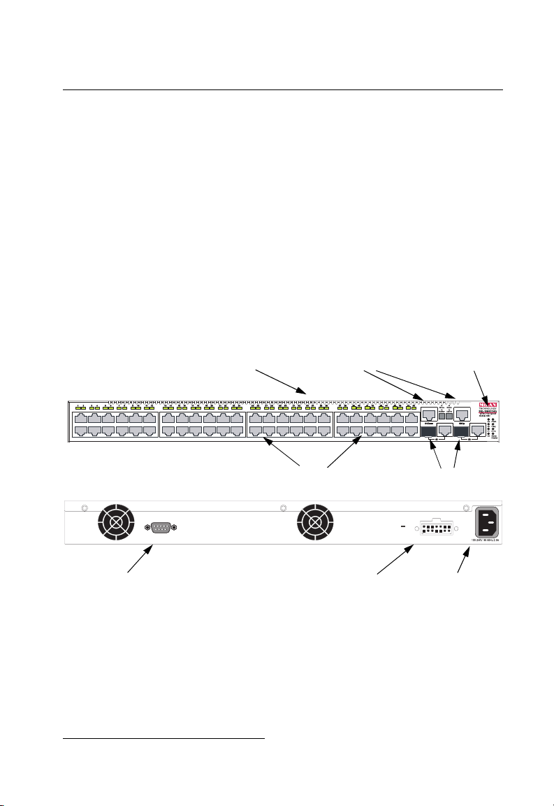
Port Status Indicators
Console
Stacking Ports
10/100 Mbps RJ-45 Ports
System Indicators
1000BASE-T/SFP Ports
RPS
DC
12V4.5A
Console Port
Redundant Power Socket
Power Socket
Figure 1-1 Front and Rear Panels
1. If an SFP transceiver is plugged in, the corresponding RJ-45 port (25-26 or 49-50) is disabled.
1-1

Introduction
1
Switch Architecture
The MIL-SM4804G employs a wire-speed, non-blocking switching fabric2. This
permits simultaneous wire-speed transport of multiple packets at low latency on all
ports. The switches also features full-duplex capability on all ports, which effectively
doubles the bandwidth of each connection.
The switches uses store-and-forward switching to ensure maximum data integrity.
With store-and-forward switching, the entire packet must be received into a buffer
and checked for validity before being forwarded. This prevents errors from being
propagated throughout the network.
The switches include built-in stacking ports that allow multiple units to connected
together through a 4 Gbps stack backplane. The switch stack can be managed from
a master unit using a single IP address.
Network Management Options
With a comprehensive array of LEDs, the MIL-SM4804G switch provides “at a
glance” monitoring of network and port status. The switches can be managed over
the network with a web browser or Telnet application, or via a direct connection to
the console port. The switches includes a built-in network management agent that
allows them to be managed in-band using SNMP or RMON (Groups 1, 2, 3, 9)
protocols. They also have an RS-232 serial port (DB-9 connector) on the front panel
for out-of-band management. A PC may be connected to this port
and monitoring out-of-band via a
options.)
For a detailed description of the advanced features, refer to the Management Guide.
null-modem serial cable. (See Appendix B for wiring
for configuration
Description of Hardware
10BASE-T/100BASE-TX Ports
The MIL-SM4804G switch contains 48 10BASE-T/100BASE-TX RJ-45 ports. All
ports support automatic MDI/MDI-X operation, so you can use straight-through
cables for all network connections to PCs or servers, or to other switches or hubs.
(See “10BASE-T/100BASE-TX Pin Assignments” on page B-1.)
Each of these ports support auto-negotiation, so the optimum transmission mode
(half or full duplex), and data rate (10 or 100 Mbps) can be selected automatically. If
a device connected to one of these ports does not support auto-negotiation, the
communication mode of that port can be configured manually.
2. Non-blocking switching is used for traffic crossing ports attached to the same switch ASIC;
while blocking is employed for traffic passing between different switch chips. The
MIL-SM4804G has two switch chips – ASIC#1: Ports 1-12, 25-36, 49, 51 and ASIC#2: Ports
13-24, 37-48, 50, 52.
1-2

Description of Hardware
Each port also supports IEEE 802.3x auto-negotiation of flow control3, so the switch
can automatically prevent port buffers from becoming saturated.
1000BASE-T/SFP Ports
These are combination Gigabit RJ-45 ports with shared Small Form Factor
Pluggable (SFP) transceiver slots (See Figure 1-1, Ports 25-26/49-50). If an SFP
transceiver (purchased separately) is installed in a slot and has a valid link on the
port, the associated RJ-45 port is disabled.
The 1000BASE-T RJ-45 ports support automatic MDI/MDI-X operation, so you can
use straight-through cables for all network connections to PCs or servers, or to other
switches or hubs. (See “1000BASE-T Pin Assignments” on page B-3.)
1
3. Flow control is only supported for ports attached to the same switch ASIC. The MIL-SM4804G
has two switch chips– ASIC#1: Ports 1-12, 25-36, 49, 51 and ASIC#2: Ports 13-24, 37-48, 50,
52.
1-3
Introduction
1
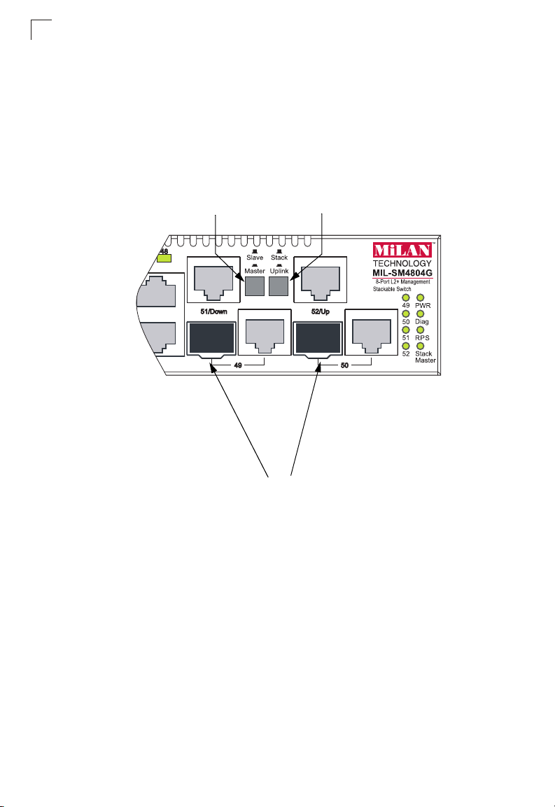
Stacking Ports
The unit provides two stacking ports that provide a 4 Gbps stack backplane
connection. You can stack up to four MIL-SM4804G units using Category 5 Ethernet
cables (purchased separately). The Master button enables one switch in the stack to
be selected as the master. This is the unit through which you manage the entire
stack.
The stacking ports can also be used as normal Ethernet ports in standalone mode
by pressing the Uplink button.
Master Button
Figure 1-2 Stacking Ports
Uplink Button
Stacking Ports
1-4
Description of Hardware
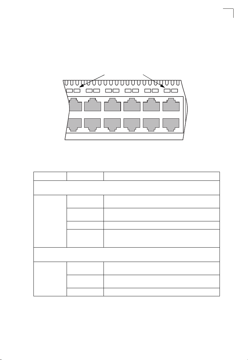
Port and System Status LEDs
The MIL-SM4804G includes a display panel for key system and port indications that
simplify installation and network troubleshooting. The LEDs, which are located on
the front panel for easy viewing, are shown below and described in the following
tables.
Port Status LEDs
4
5
1
3
2
6
7
Figure 1-3 Port LEDs
Table 1-1 Port Status LEDs
LED Condition Status
Fast Ethernet Ports
MIL-SM4804G: Ports 1-48
(Link/Activity) On/Flashing
Amber
On/Flashing
Green
Port has established a valid 10 Mbps network connection.
Flashing indicates activity.
Port has established a valid 100 Mbps network connection.
Flashing indicates activity.
Off There is no valid link on the port.
Flashing Green W hen the “light unit” command is entered in the Co mmand Line
Interface, the LE D corresponding to the switch’s ID will fla sh for
about 15 seconds.
Gigabit Ethernet Ports
MIL-SM4804G: Ports 49-50, and Ports 51-52 when stacking is not implemented
(Link/Activity) On/Flashing
Amber
On/Flashing
Green
Port has established a valid 10/100 Mbps network connection.
Flashing indicates activity.
Port has established a valid 1000 Mbps network connection.
Flashing indicates activity.
Off There is no valid link on the port.
9
8
11 12
10
1
1-5
 Loading...