

Page 1
24-Port + One Dual-Module
Expansion Slot
Stackable Managed Switch
MIL-SM2401M-STK
USER GUIDE
Page 2

Regulatory Approval
- FCC Class A
- UL 1950
- CSA C22.2 No. 950
- EN60950
- CE
- EN55022 Class A
- EN55024
Canadian EMI Notice
This Class A digital apparatus meets all the requirements of the Canad ian Interference-Causing Equipment Regulations.
Cet appareil numerique de la classe A respecte toutes les exigences du Reglement sur le materiel brouilleur du Canada.
European Notice
Products with the CE Marking comply with both the EMC Directive (89/336/EEC) and the Low Voltage Directive (73/23/EEC) issued
by the Commission of the European Communi ty Compliance with these directives imply conformity to the following European Norms:
EN55022 (CISPR 22) - Radio Frequency Interference
EN61000-X - Electromagnetic Immunity
EN60950 (IEC950) - Product Safety
MiLAN Technology warrants to the original consumer or purchaser that each of it's products,
and all components thereof, will be free from def ects in material and/or workmanship for a
period of five years from the original factory shipment date. Any warranty hereunder is
extended to the original consumer or purchaser and is not assignabl e.
MiLAN Technology makes no express or implied warranties including, but not limited to, any
implied warranty of merchantability or fitness for a particular purpose, except as expressly set
forth in this warranty. In no event shall MiLAN Technology be liable for incidental or
consequential damages, costs, or expenses arising out of or in connection with the
performance of the product delivered hereunder. MiLAN Techno logy will in no case cover
damages arising out of the product being used in a negligent fashion or manner.
Trademarks
The MiLAN logo and MiLAN Technology trademarks are registered trademarks of MiLAN Technology in the
United States and/or other countries.
To Contact MiLAN Technology
For prompt response when calling for service information, have the following information ready:
- Product serial number and revision
- Date of purchase
- Vendor or place of purchase
You can reach MiLAN Technology technical support at:
E-mail: support@milan.com
Telephone: +1.408.744.2751
Fax: +1.408.744.2771
MiLAN Technology
1329 Moffett Park Drive
Sunnyvale, CA 94089
United States of Amer ic a
Telephone: +1.408.744.2775
Fax: +1.408.744.2793
http://www.milan.com
info@milan.com
© Copyright 2005 MiLAN Technology P/N: 90000416 Rev. x
Five-Year Limited Warranty
Page 3

Table of Contents
1. Introduction
Features
Ethernet Switching Technology
2. Hardware Description
Front Panel
Rear Panel
3. Network Application
4. Console Management
Connecting a Terminal or PC to the Console Port
Communication Parameters
Console - Login
Console Management Options
5. CLI Management Interface
Software Features
Package Contents
Management Methods
Console and Telnet Management
Web-based Management
SNMP Network Management
LED Indicators
Desktop Installation
Rack-mounted Installation
Power On
Small Workgroup
Segment Bridge
Stacking Workgroup
5-1. Commands Level
5-2. Commands Set List
5-2-1. System Commands Set
5-2-2. Port Commands Set
5-2-3. Trunk Commands Set
5-2-4. VLAN Commands Set
Page 4

5-2-5. Spanning Tree Commands Set
5-2-6. QoS Commands Set
5-2-7. IGMP Commands Set
5-2-8. Mac/Filter Table Commands Set
5-2-9. SNMP Commands Set
5-2-10. Port Mirroring Comman d s Set
5-2-11. Stacking Comm ands Set
5-2-12. 802.1x Commands Set
5-2-13. TFTP Commands Set
6. Console Menu Management
6-1. Main Menu
6-2. Status and Counters
6-2-1. Port Status
6-2-2. Port Counters
6-2-3. System Information
6-3. Switch Configuration
6-3-1. Administration Configuration
6-3-1-1. Device Information
6-3-1-2. IP Configuration
6-3-1-3. User Name Configuration
6-3-1-4. Password Conf iguration
6-3-2. Port Configuration
6-3-3. Trunk Configur ation
6-3-4. Port Mirroring Configuration
6-3-5. VLAN Configur ation
6-3-5-1. VLAN Configure
6-3-5-2. Create a VLAN Group
6-3-5-3. Edit / Delete VLAN Group
6-3-5-4. Groups Sorted Mode
6-3-6. Priority Configuration
6-3-7. MAC Address Configuration
6-3-7-1. Static MAC Address
6-3-7-2. Filtering MAC Address
6-3-8. Miscellaneous Configur at ion
Page 5

6-3-8-1. MAC Address Ageing Time
6-3-8-2. Broadcast Storm Filt ering
6-3-8-3. Max Bridge Tr ansmit Delay Bound
6-3-8-4. Collision Retry Forever
6-3-8-5. Hash Algorithm
6-3-8-6. IFG Compensat ion
6-3-8-7. IP Stacking Group ID (0…65535)
6-3-8-8. IP Stacking Mode
6-4. Protocol Relate d C onfiguration
6-4-1. STP
6-4-1-1. STP Setup
6-4-1-2. System Configuration
6-4-1-3. STP Per Port Setting
6-4-2. SNMP
6-4-2-1. SNMP System Options
6-4-2-2. Community Strings
6-4-2-3. Trap Managers
6-4-3. LACP
6-4-3-1. LACP Working Ports
6-4-3-2. LACP State Activity
6-4-3-3. LACP Group Status
6-4-4. IGMP/GVRP Configuration
6-4-5. 802.1X Configurati on
6-4-5-1. 802.1X Setup
6-4-5-2. 802.1X System Configurat i on
6-4-5-3. 802.1X Per Port Configuration
6-4-5-4. 802.1X Miscellaneous Conf igur at i on
6-5. System Reset Configuration
6-5-1. Factory De fault
6-5-2. System Reboot
6-5-3. TFTP Configur ation
6-5-3-1. TFTP Update Firmware
6-5-3-2. TFTP Restore Conf iguration
6-5-3-3. TFTP Backup Confi guration
Page 6

6-5-3-4. Save Configuration
6-6. Xmodem Upgrade
7. Web-Based Management
7-1. System Login
7-2. Port Status
7-3. Port Statistics
7-4. Administrator
7-4-1. IP Address
7-4-2. Switch Setting
7-4-2-1. Basic Switch Settings
7-4-2-2. Advanced Settings
7-4-2-3. Miscellaneous Sett ings
7-4-3. Console Port Information
7-4-4. Port Controls
7-4-5. Trunking
7-4-5-1. Aggregator Setting
7-4-5-2. Aggregator Information
7-4-5-3. State Activity
7-4-6. Forwarding and Filtering
7-4-6-1. IGMP Snooping
7-4-6-2. Static MAC Address
7-4-6-3. MAC Filtering
7-4-7. VLAN Configur ation
7-4-7-1. VLAN Operation Mode 802.1Q (802.1Q VLAN)
7-4-8. Spanning Tree
7-4-8-1. System Configuration
7-4-8-2. Per Port Configurat ion
7-4-9. Port Mirroring
7-4-10. SNMP Management
7-4-10-1. System Options
7-4-10-2. Community Strings
7-4-10-3. Trap Managers
7-4-11. Security Manager
7-4-12. 802.1X
Page 7

7-4-12-1. System Configuration
7-4-12-2. Per Port Configuration
7-4-12-3. 802.1X Miscellaneous Configuration
7-4-13. TFTP Update Firmware
7-4-14. Configuration Ba ckup
7-4-14-1. TFTP Restore Configuration
7-4-14-2. TFTP Backup Configuration
7-4-15. Factory Default
7-4-16. System Reboot
7-5. Panel List
7-6. IP Stacking
7-6-1. Setting up an IP Stacking Group
8. Troubleshooting
Incorrect connections
Diagnostic LED Indicators
9. Technical Specification s
Page 8

Page 9

1.
Introduction
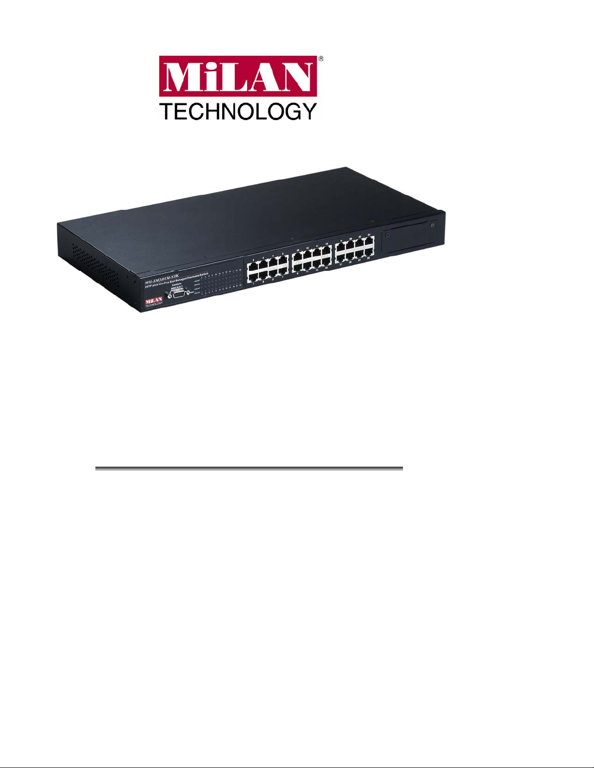
The MIL-SM2401M-STK managed switch is a multi-port switch that can be used
to build high-performance switched workgroup networks. This switch is a
store-and-forward device that offers low latency for high-speed networking. The
switch is targeted at workgroup, department or backbone computing
environments.
The switch features a “store-and-forward “ switching scheme. This allows the
switch to auto-learn and store source addresses in an 8K-entry MAC address
table.
The
MDI port does not cross transmit and receive lines, which is done by the regular
ports (MDI-X ports) that connect to end stations. In general,
connecting to another hub or switch while
workstation or PC. Therefore,
another switch or workstation without changing non-crossover or crossover
cabling.
The MIL-SM2401M-STK switch provides 24 auto-sensing 10/100Base-TX RJ-45
ports plus one dual-port expansion slot for optional fiber, gigabit fiber, or gigabit
UTP modules, which enables long-distance fiber connections or gigabit copper for
higher connection speeds.
(Medium Dependent Interface) port is also called an "uplink port". The
MDI
means
MDI
means connecting to a
MDIX
Auto MDI/MDIX
means that you can connect to
1
Page 10

Features
Conforms to IEEE802.3 10BASE-T, 802.3u 100BASE-TX/FX, 802.3ab
1000BASE-T, 802.3z Gigabit fiber
24 10/100 Ethernet ports plus one expansion slot
IEEE802.3x Flow control
Flow control for full duplex
¾
Backpressure for half duplex
¾
High back-plane bandwidth 8.8Gbps
IEEE802.3ad Port trunk with LACP
Broadcast storm filter
Stack management via single IP address
IGMP support for Multi Media application
EEE 802.1p class of service
Formatted:
Bullets and Numbering
Port security
Port bandwidth control
IEEE 802.1d Spanning tree protocol
GVRP function
Port based VLAN/802.1Q VLAN
IEEE 802.1x user authentication
DHCP client
SNMP, Telnet, Web and Local console management
Provides command line interface for telnet and local console
management
Modules include: 2 x 100FX, 2 x 1000SX, 1000T + 1000SX, 1000T +
1000LX, 2 x 1000T, 2 MINI GBIC
2
Page 11

Software Features
Provides SNMP, Web browser, Telnet and local RS-232
Management
RFC Standard
console management. The telnet and console also
supports command line interface.
RFC 1157 SNMP, RFC 1213 MIB II, RFC 1643 Ethernet
like, RFC 1493 Bridge MIB, RFC 1757 RMON 1, RFC 1215
Trap, RFC 2674 VLAN MIB, private MIB.
SNMP Trap
Software Upgrade TFTP and Console firmware upgradeable
Port Trunk
Spanning Tree IEEE802.1d Spanning Tree
VLAN
QOS Policy Supports 8 priority levels ID for two priority queues
Cold start, link down, link up, authorization fail, Trap station
up to 3.
Supports IEEE802.3ad with LACP function. Up to 7 trunk
groups and group member up to 4. The trunk port within
24-port 10/100TX and extension module.
Port based VLAN
IEEE802.1Q Tag VLAN
IEEE802.1v Protocol VLAN (IP, IPX, etc.)
The static VLAN groups up to 256 and dynamic VLAN
groups up to 2048, the VLAN ID can be assigned from 0 to
4094.
Per system supports high and low queues. The priority
Class of Service
3
service rule: first come first service, all High before Low,
WRR for high or low weight.
Page 12

Port Based Priority
Supports 3 settings: “Disable, Low or High priority”. When
set to “Disable”, the incoming packet will follow QoS policy;
Otherwise, the packet will follow port priority setting to
“High/Low” queue.
IGMP
Supports IGMP snooping for Multi-Media application and
supports 256 groups
Supports ingress and egress MAC address filter and static
Port Security
source MAC address lock.
Global system supports 3 mirroring types: “RX, TX and
Port Mirror
Both packet”. The maximum of port mirror entries is up to
25.
Bandwidth Control Each port supports bandwidth control. Per level 100Kbps.
Supports single IP management feature, stacked up to 8
Stacking
units. Stacking and switch management can be through
any port, including the uplink module.
Supports IEEE802.1x User-Authentication and can report
to RADIUS server.
Reject
802.1x
Accept
Authorize
Disable
DHCP DHCP Client
Packet filter Broadcast storm
4
Page 13

Package Contents
Unpack the contents of the package and verify them against the checklist below.
MIL-SM2401M-STK Switch
Power Cord
Four Rubber Feet
Rack Mount Ears
RS-232 cable
User Guide (CD Manual)
Warranty Card
If any item is missing or damaged, please contact your local dealer for service.
Management Methods
The MIL-SM2401M-STK switch series supports the following management
methods:
Console and Telnet Management
Web-based Management
SNMP Network Management
Console and Telnet Management
Console Management is done through the RS-232 Console Port. Managing the
switch in this method requires a direct connection between a PC and the switch.
Telnet management requires a network connection. The default IP address is
5
Page 14

192.168.1.77 with a subnet mask of 255.255.255.0. This default address can be
used to login and change the configuration using Telnet.
Web-based Management
The switch provides an embedded HTML web server residing in flash memory. It
offers advanced management features and allows users to manage the switch
from anywhere on the network through a standard browser such as Microsoft
Internet Explorer or Netscape.
SNMP Network Management
SNMP (Simple Network Management Protocol) provides a means to monitor and
control network devices, and to manage configurations, statistic collection,
performance, and security.
6
Page 15

Ethernet Switching Technology
Ethernet Switching Technology dramatically boosted the total bandwidth of a
network, eliminated congestion problems inherent with CSMA/CD (Carrier Sense
multiple access with Collision Detection) protocol, and greatly reduced
unnecessary transmissions.
This revolutionized networking. First, by allowing two-way, simultaneous
transmissions over the same port (Full-duplex), that essentially doubled the
bandwidth. Second, by reducing the collision domain to a single switch-port, that
eliminated the need for carrier sensing. Third, by using the store-and-forward
technology’s approach of inspecting each packet to intercept corrupt or redundant
data, switching eliminated unnecessary transmission that slow the network. By
employing address learning, which replaced the inefficient receiving port.
Auto-negotiation regulates the speed and duplex of each port, based on the
capability of both devices. Flow-control allows transm issio n from a 100M bps node
to a 10Mbps node without loss of data. Auto-negotiation and flow-control may
require disablement for some networking operations involves legacy equipment.
Disabling the auto-negotiation is accomplished by fixing the speed or duplex of a
port.
Ethernet Switching Technology supplied higher performance at costs lower than
other solutions. Wider bandwidth, no congestion, and the reduction in traffic is
why switching is replacing expensive routers and inefficient hubs as the ultimate
networking solution. Switching brought a whole new way of thinking to networking.
7
Page 16
2.
Hardware Description
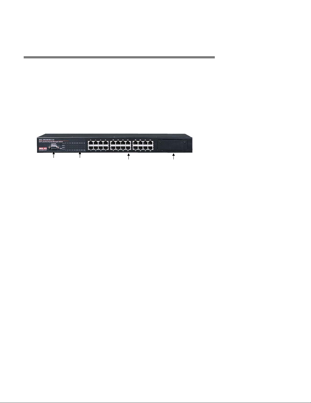
Front Panel
The Front Panel of the MIL-SM2401M-STK switch series consists of 24
10/100Base-TX RJ-45 ports (Auto MDI/MDIX) and one expansion slot. The LED
Indicators and console port are also located on the front panel of the switch.
Console LED Fast Ethernet Ports Module Bay
Port Indicators
Figure 2-1. Front panel for MIL-SM2401M-STK
100BASE-TX UTP Ports:
Fast Ethernet UTP ports.
Modules:
modules. Check with your MiLAN sales representative for details.
Console Port:
It requires a direct connection between the switch and an end station (PC) via
a RS-232 cable.
The MIL-SM2401M-STK provides a broad range of expansion slot
Console management can be done through the Console Port.
The MIL-SM2401M-STK comes with 24 100Mbps
8
Page 17
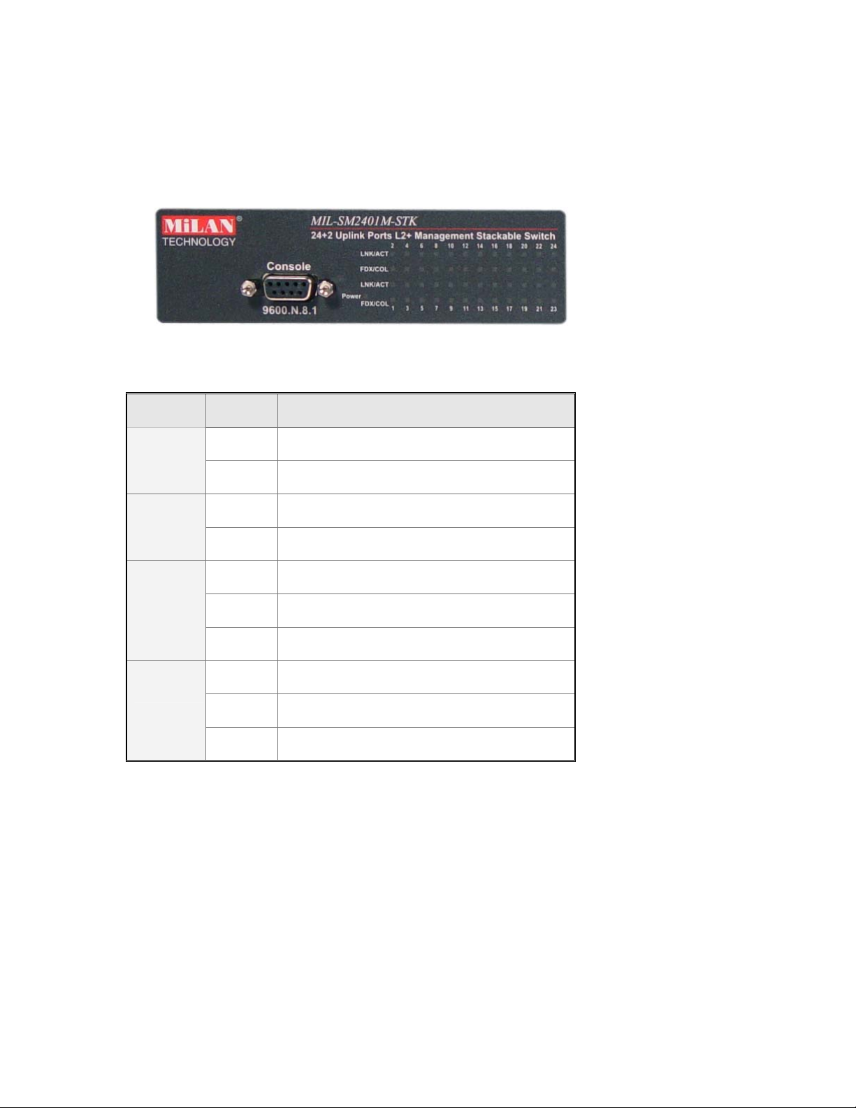
LED Indicators
The LED Indicators give real-time information of systematic operation status. The
following table provides descriptions of LED statuses and their meaning.
Figure 2-2. LED Indicators
LED Status
Description
Green Power On
Power
Off Power is not connected
Green The port is in 100Mbps speed.
100M
Off The port is in 10Mbps speed.
Green The port is connecting with the device.
LNK/ACT
Blinks The port is receiving or transmitting data.
Off No device attached.
Orange The port is operating in Full-duplex mode.
FDX/COL
Blinks Collision of Packets is occurring on the port.
Off The port is operating in half-duplex mode
Table 2-1. The Description of LED Indicators
9
Page 18

Rear Panel
The 3-pronged power plug is located at the rear panel of the MIL-SM2401M-STK
as shown in Figure 2-3. The Switch will work with AC in the range 100-240V AC,
50-60Hz.
Figure 2-3. The Rear Panel of the 24 10/100TX plus one Exp. Slot stackable switch
10
Page 19
Desktop Installation
Set the switch on a sufficiently large flat space with a power outlet nearby. The
surface where you put your switch should be clean, smooth, level and sturdy.
Provide enough clearance around the switch to allow attachment of cables, power
cord and allow air circulation.
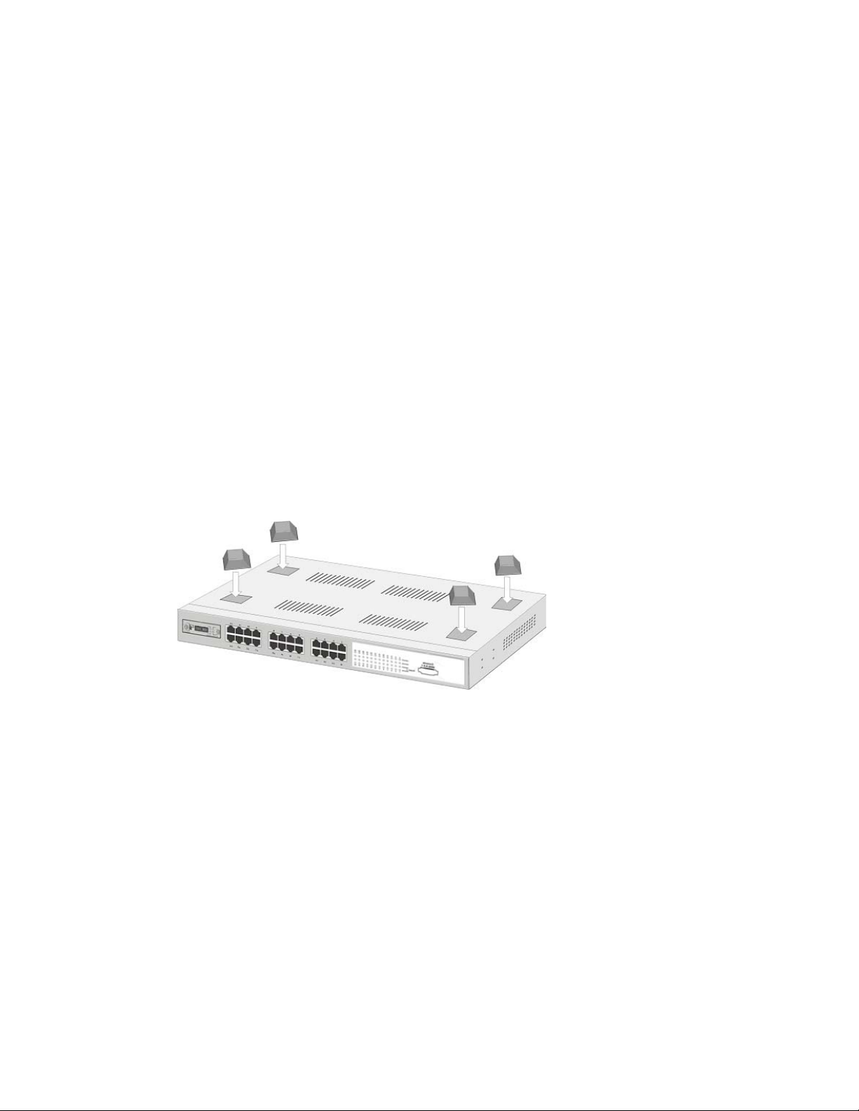
Attaching Rubber Feet
A. Make sure the mounting surface on the bottom of the switch is grease and
dust free.
B. Remove adhesive backing from your Rubber Feet.
C. Apply the Rubber Feet to each corner on the bottom of the switch.
These footpads can prevent the switch from shock/vibration.
Figure 2-4. Attaching Rubber Feet to each corner on the bottom of the switch
11
Page 20
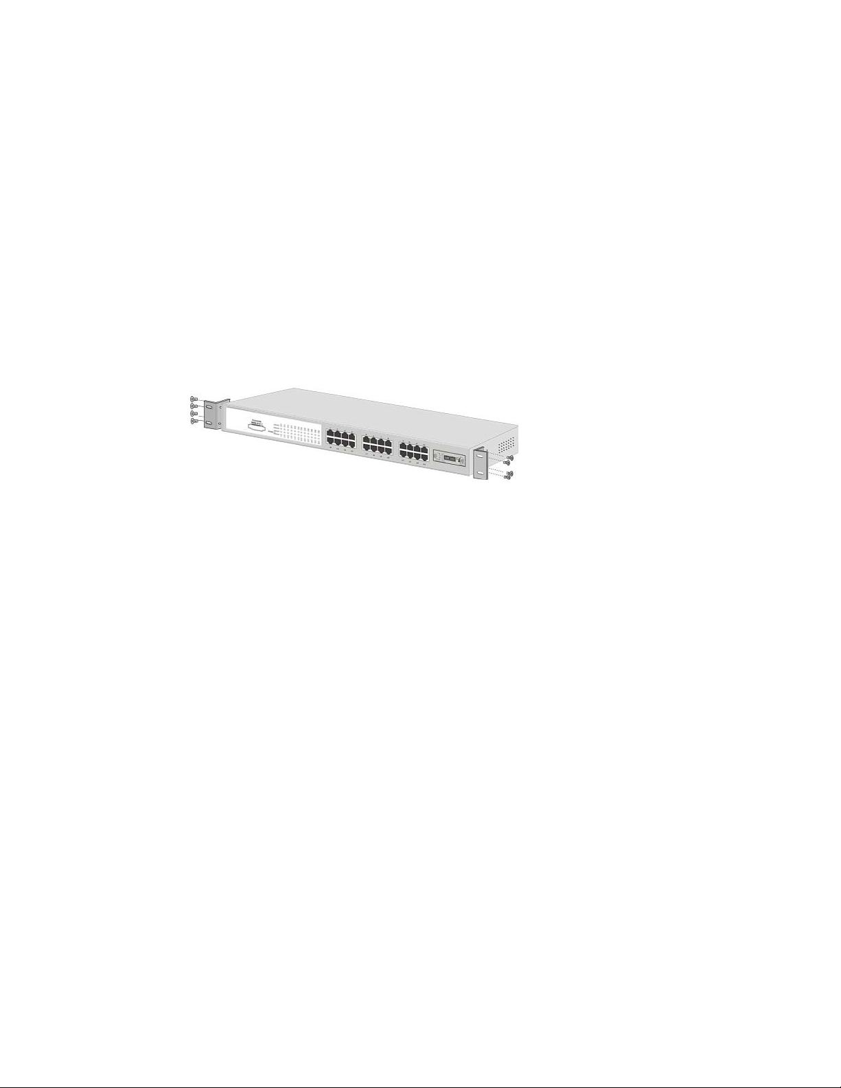
Rack-mounted Installation
The MIL-SM2401M-STK switch come with a rack-mounted kid and can be
mounted in an EIA standard size, 19-inch Rack. The switch can be placed in a
wiring closet with other equipment.
Perform the following steps to rack mount the switch:
A. Position one bracket to align with the holes on one side of the switch and
secure it with the smaller bracket screws. Then attach the remaining bracket
to the other side of the Switch.
Figure 2-5. Attach mounting brackets with screws
12
Page 21
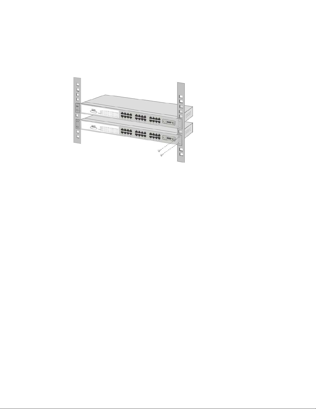
B. After attaching both mounting brackets, position the MIL-SM2401M-STK in
the rack by lining up the holes in the brackets with the appropriate holes on
the rack. Secure the switch to the rack with a screwdriver and the
rack-mounting screws.
Figure 2-6. Mount the switch in an EIA standard 19-inch Rack
For proper ventilation, allow about at least 4 inches (10 cm) of clearance on the
Note:
front and 3.4 inches (8 cm) on the back of the Switch. This is especially important for
enclosed rack installation.
Power On
Connect the power cord to the power socket on the rear panel of the switch.
Connect the other end of the power cord to an appropriate power outlet. The
internal power supply of the switch works with voltage range of AC in the
100-240VAC, f requency 50~60Hz.
Press the power On/Off switch to the On position and check the power indicator
on the front panel to see if power is properly supplied.
13
Page 22

3.
Network Application
This section provides you a few samples of network topology in which the Switch
is used. In general, the 24 10/100TX plus one Exp. Slot Single IP Stackable
Switch is designed as a segment switch. That is, with its large address table
(8000 MAC address) and high performance, it is ideal for interconnecting
networking segments.
PC, workstations, and servers can communicate each other by directly
connecting with 24 10/100TX plus one Exp. Slot Single IP Stackable Switch. The
switch automatically learns nodes address, which are subsequently used to filter
and forward all traffic based on the destination address.
By using Uplink port, the Switch can connect with another switch or hub to
interconnect other small-switched workgroups to form a larger switched network.
Meanwhile, you can also use fiber ports to connect switches. The distance
between two switches via fiber cable can be up to 2 kilometer (multi-mode fiber)
or 60 kilometer (single-mode fiber).
14
Page 23
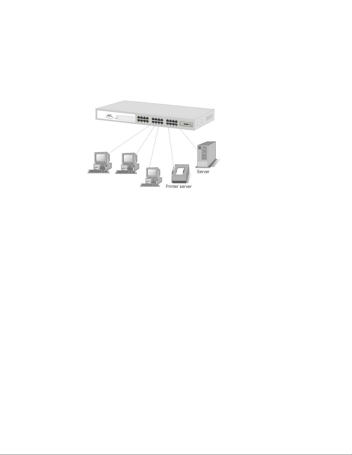
Small Workgroup
The MIL-SM2401M-STK switch can be used as a standalone switch to which
personal computers, servers and printer servers are directly connected to form a
small workgroup.
Figure 3-1. Small Workgroup Application
15
Page 24
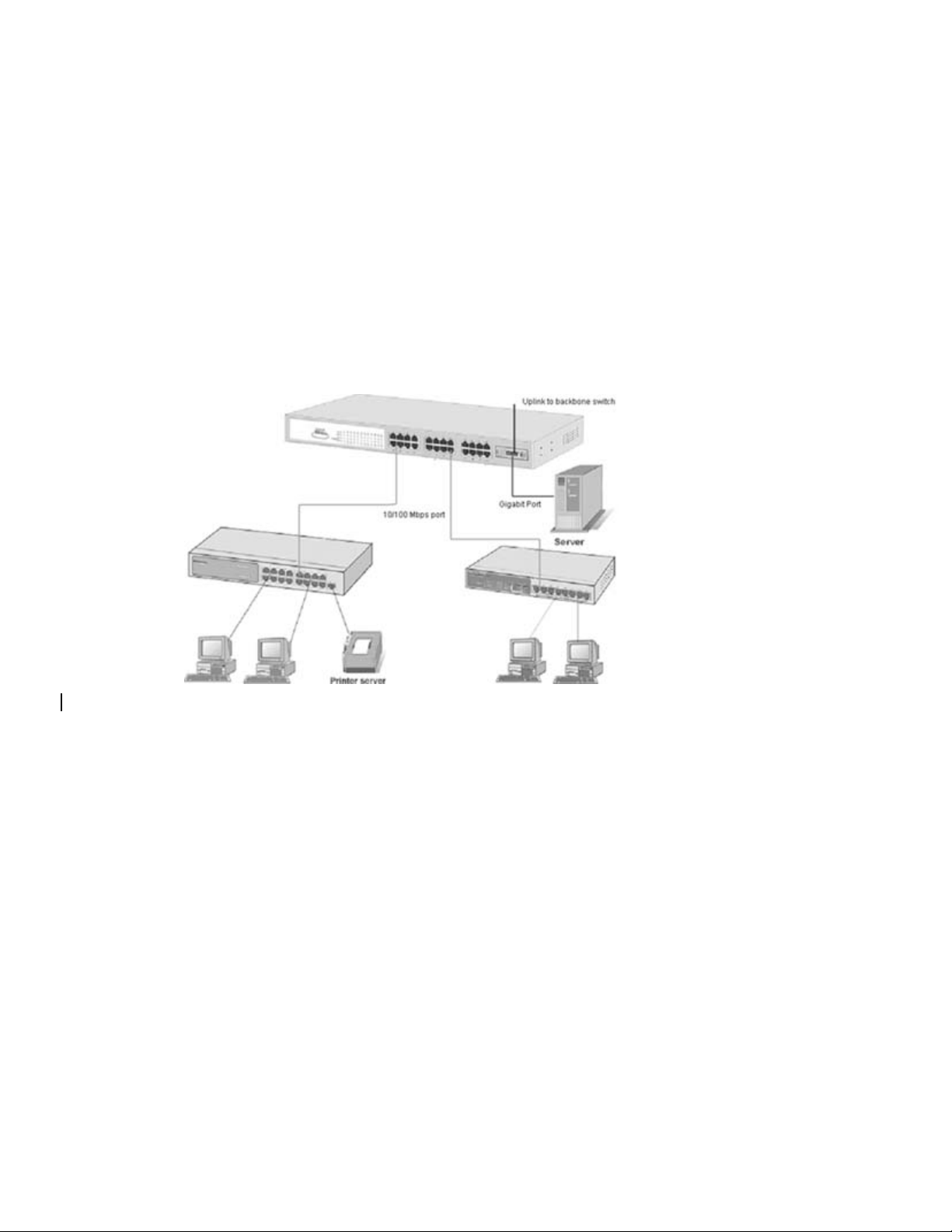
Segment Bridge
For enterprise networks where large data broadcasts are constantly processed,
this switch is an ideal solution for department users to connect to the corporate
backbone.
In the illustration below, two Ethernet switches with PCs, print servers, and local
servers attached, are both connected to the switch. All the devices in this network
can communicate with each other through the switch. Connecting servers to the
switch allows other users to access the data on server.
Figure 3-2 Department Bridge Application
16
Page 25
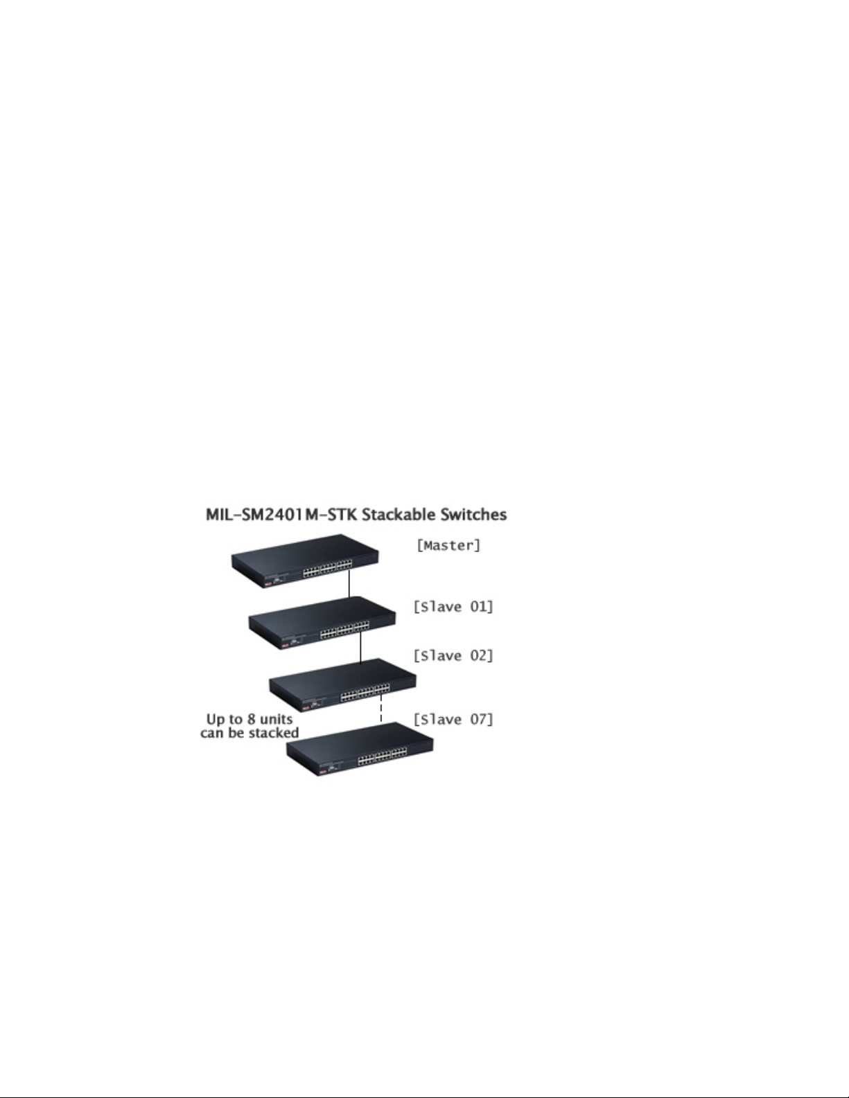
Stacking Workgroup
Up to eight (8) individual MIL-SM2401M-STK switches can be connected to form
a single logical unit using embedded stacking technology. The stack behaves as a
single switching unit that is manageable by a master switch elected from one of
the member switches.
The master switch serves as the control center for the stack and automatically
creates and updates all of the switching tables. The remaining member switches
act as forwarding processors and each switch in the stack is assigned to a single
workgroup ID. In addition, a working stack can accept new members or delete
old ones without service interruption or degraded performance.
No special tools, extra software, or expensive equipment is needed to form a
Stacking Workgroup. With the MIL-SM2401M-STK, management applications
represent the entire stack as a single device with simple point and click
management.
Figure 3-3. A stacking workgroup application
17
Page 26
4.
Console Management
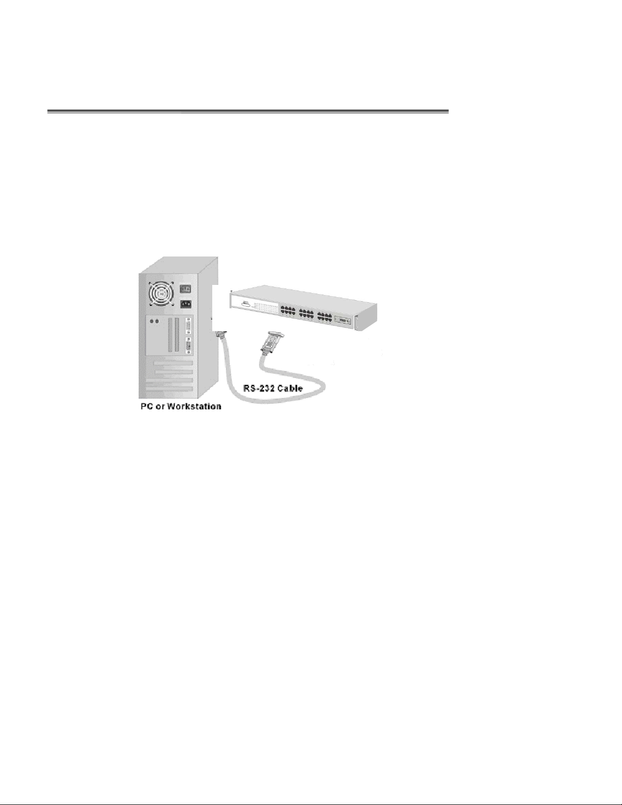
Connecting a Terminal or PC to the Console Port
Console management involves the administration of the switch via a direct
connection to the RS-232 console port. This port is a female DB-9 connector.
From the main menu of the console program, the user has access to manage the
functions of the switch.
Figure 4-1. Connecting the switch to a terminal via RS-232 cable
Use the supplied RS-232 cable to connect a terminal or PC to the console port.
The terminal or PC to be connected must support the terminal emulation program.
18
Page 27
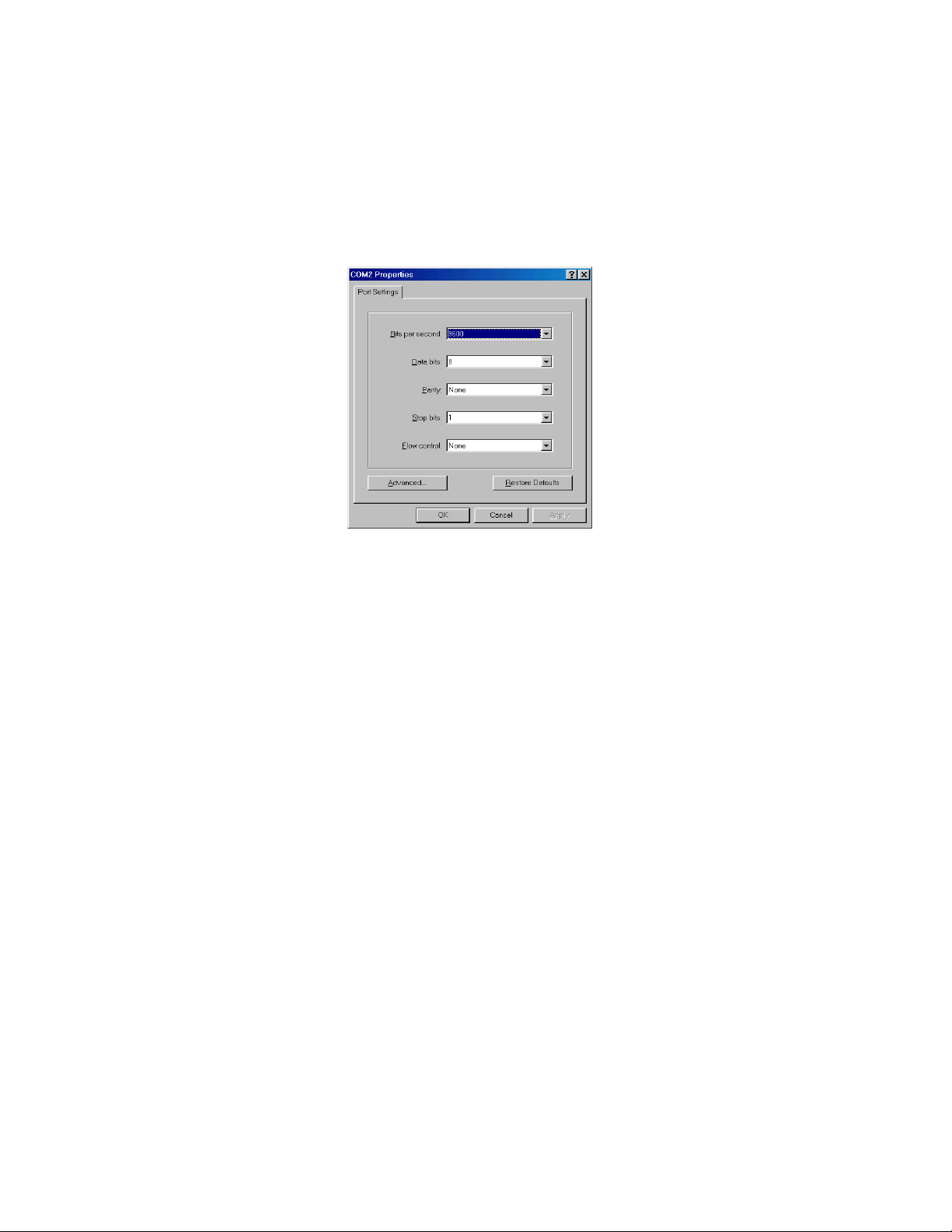
Communication Parameters
After the connection between Switch and PC is finished, turn on the PC and run a
terminal emulation program
or
Hyper Terminal
characteristics of the console port:
Baud Rate: 9600 bps
Data Bits: 8
Parity: none
Stop Bit: 1
Control flow: None
Figure 4-2. The settings of communication parameters
to match the following default
19
Page 28

Console - Login
After you have entered the parameter settings, click OK. When the blank screen
appears, press the
password to login. The default user name is
Key to access the login screen. Type the user name and
Enter
; the default password is
root
Figure 4-3. Console login screen
root
.
1. The switch also provides a serial interface to manage and monitor the switch.
The user can follow the Console Port Information provided by the web to use
the Windows HyperTerminal program to link the switch.
2. Type the user name and password to login. The default user name is
default password is
root
.
root
; the
3. The timeout on the console port is 60 seconds. If no action is taken on the
console screen for one minute, the program reverts back to the logon screen
and a new login is necessary in order to continue.
20
Page 29

4. The switch is shipped with a default IP address of 192.168.1.77. The default
subnet mask is 255.255.255.0.
21
Page 30

Console Management Options
The system supports two types of console management – CLI Command and
Menu Selection. After you login to the system, you will see a command prompt.
To enter the Menu Selection management interface, type “
prompt and you will see the main menu interface.
To enter CLI Command management interface, type “
enable
prompt.
” at the command
menu
” at the command
22
Page 31

5.
CLI Management Interface
To enter CLI Command management interface, type “
enable
prompt. The following tables list the CLI commands and descriptions.
5-1. Commands Level
” at the command
Modes
User EXEC
Privileged
EXEC
Access
Method
Begin a
session with
your switch.
Enter the
enable
command
while in user
EXEC mode.
Prompt
Switch>
Switch#
Exit
Method
Enter logout
or quit.
Enter
disable to
exit.
About This Mode1
The user commands
available at the user
level are a subset of
those available at the
privileged level.
Use this mode to
• Perform basic tests.
• Display system
information.
The privileged
command is advance
mode
Privileged this mode to
• Display advance
function status
• Save configures
Global
Enter the
configure
Configuration
command
23
Switch
(config)#
To exit to
privileged
EXEC
Use this mode to
configure parameters
that apply to your
Page 32

VLAN
database
Interface
configuration
while in
privileged
EXEC mode.
Enter the vlan
database
command
while in
privileged
EXEC mode.
Enter the
interface
command
(with a
specific
interface)
while in global
configuration
mode
Switch
(vlan)#
switch
(config-if)#
mode, enter
exit or end
To exit to
user EXEC
mode, enter
exit.
To exit to
global
configuratio
n mode,
enter exit.
To exist to
privileged
EXEC
mode, or
end.
switch as a whole.
Use this mode to
configure
VLAN-specific
parameters.
Use this mode to
configure parameters
for the switch and
Ethernet ports.
24
Page 33

5-2. Commands Set List
5-2-1. System Commands Set
Commands
system name
[systemname]
system location
[system
location]
system
description
[systemdescript
ion]
system contact
[systemcontact]
ip address
[ip-address]
[subnet-mask ]
[ gateway]
Command
Level
Global
configuration
mode
Global
configuration
mode
Global
configuration
mode
Global
configuration
mode
Global
configuration
mode
Description Defaults Example
Set switch system
name string
Set switch system
location string
Set switch system
description string
Set switch system
contact window string
Use the ip address
interface configuration
command to set an IP
address for a switch.
Use the no form of this
command to remove
an IP address or to
disable IP processing.
Switch (config)#
system name xxx
Switch (config)#
system location
xxx
Switch (config)#
system
description xxx
Switch (config)#
system contact
xxx
Switch (config)#
ip address
192.168.1.1
255.255.255.0
192.168.1.254
25
Page 34

reload
default
username
[user-name]
password
[password]
show system
info
Global
configuration
mode
Global
configuration
mode
Global
configuration
mode
Global
configuration
mode
User EXEC
Halt and perform a
cold restart
Restore to default
Changes a login
username. (maximum
10 words)
Specifies a password
(maximum 10 words)
Show system
information
Switch (config)#
reload
Switch (config)#
Default
Switch (config)#
username xxxxxx
Switch (config)#
Password xxxxxx
Switch> show
system info
Name: switch1
location: lab
Description:
layer2 switch
Contact:
somewhere
Serial NO: 1.00
show ip
Privileged
EXEC
Show ip information
26
Switch# show ip
Address ip:
192.168.1.1
Address subnet:
255.255.255.0
Address
gateway:
192.168.1.254
Page 35

show
accounting
Privileged
EXEC
show version User EXEC
Privileged
show terminal
EXEC
Show username &
password
Use the show version
user EXEC command
to display version
information for the
hardware and
firmware.
Use the show terminal
command to display
console information
for the switch
Switch# show
accounting
Username: root
Password: root
Switch> show
version
Firmware
version: 1.0
Hardware
version: 3.0
Kernel version:
1.10
Switch (config)#
show terminal
Baud rate
(bits/sec): 9600
Data Bits: 8
Parity Check:
none
Stop Bits: 1
Flow Control:
none
27
Page 36

5-2-2. Port Commands Set
Commands
interface
[FastEthernet
/module
Ethernet] [slot
id] [id]
duplex [full | half|
auto]
Command
Level
Interface
configuration
mode
Interface
configuration
mode
Description Defaults Example
Use the fast Ethernet
interface
configuration
command
Use the module
Ethernet interface
configuration
command
Use the duplex
configuration
command to specify
Auto
the duplex mode of
operation for Fast
Ethernet.
Use the duplex
configuration
command to specify
Auto
the duplex mode of
operation for module
Ethernet.
Switch (config)#
interface
fastEthernet 0/1
Switch (config)#
interface
moduleEthernet 1/1
Switch (config)#
interface
fastEthernet 0/1
Switch (config-if)#
duplex full
Switch (config)#
interface
moduleEthernet 1/1
Switch (config-if)#
duplex full
28
Page 37

speed
[10 | 100 | 1000 |
auto]
speed [10| 100 |
1000 | auto]
Interface
configuration
mode
Interface
configuration
mode
Use the speed
configuration
command to specify
the speed mode of
operation for Fast
Ethernet.
Use the speed
configuration
command to specify
the speed mode of
operation for module
Ethernet.
(The 100Base-FX
module only
supported for speed
100)
(The 1000Base-FX
module only
supported for speed
1000 & auto)
Auto
Switch (config)#
interface
fastEthernet 0/1
Switch (config-if)#
speed 10
Switch (config)#
interface
fastEthernet 1/2
Switch (config-if)#
speed 1000
Use the flow control
configuration
command on
Ethernet ports to
Interface
flowcontrol on or
control traffic rates
configuration
no flowcontrol
during congestion.
mode
Use the no form of
this command to
disable security on
the port.
29
Switch (config)#
interface
On
fastEthernet 0/1
Switch (config-if)#
flowcontrol on
Page 38

security on or no
security
priority on [hi |
low] or no
priority
Interface
configuration
mode
Interface
configuration
mode
Use the security
configuration
command on
Ethernet ports.
Use the no form of
this command to
disable security on
the port.
Use the priority
configuration
command on
Ethernet ports.
Use the no form of
this command to
disable security on
the port.
Disable
Disable
Switch (config)#
interface
fastEthernet 0/1
Switch (config-if)#
security on
Switch (config)#
interface
fastEthernet 0/1
Switch (config-if)#
priority on hi
Bandwidth [in |
out] [value]
Interface
configuration
mode
Set bandwidth in or
out rate. The value
rage is (0~999), and
zero of the value is
disable
(The module can’t be
setting)
30
Disable
Switch (config)#
interface
fastEthernet 0/1
Switch (config-if)#
bandwidth in 50
Page 39

State [Enable |
Disable]
show interface
configuration
Interface
configuration
mode
Interface
configuration
mode
Use the state
interface
configuration
command to specify
the state mode of
operation for
Ethernet ports. Use
the disable form of
this command to
disable the port.
show interface
configuration status
Enable
Switch (config)#
interface
fastEthernet 0/1
Switch (config-if)#
state disable
Switch (config)#
interface
fastEthernet 0/1
Switch (config-if)#
show interface
configuration
Interface
show interface
show interface actual
configuration
status
status
mode
Interface
show interface
show interface
configuration
accounting
statistic counter
mode
31
Switch (config)#
interface
fastEthernet 0/1
Switch (config-if)#
show interface
status
Switch (config)#
interface
fastEthernet 0/1
Switch (config-if)#
show interface
accounting
Page 40

show bandwidth
Interface
configuration
mode
Display the
bandwidth of the
values
Switch (config)#
interface
fastEthernet 0/1
Switch (config-if)#
Show bandwidth
32
Page 41

5-2-3. Trunk Commands Set
Commands
port group
[group-number]
[port-list] lacp
[on | off] workp
[work ports]
no port group
[group-number]
lacp [on | off]
workp [work
ports]
show group
[group-ID]
Command
Level
Global
configuration
mode
Privileged
EXEC mode
Description Defaults Example
LACP:
Add trunking
group.
Use the no form of
this command to
delete trunking
group.
Display trunk group
information. If there
is no group-number
in put, display all
trunk groups.
Disable
Switch (config)# port
group 1 1-4
lacp on workp 2
Trunk without LACP:
Switch (config)# port
group 1 1-4
lacp off workp 4
Switch # show group
1
Group Trunk.1:
Ports: 02 03 04
Priority: 0001
Lacp: Enable
Work ports: 0
port group
[group-number]
activityport
[port-list]
33
Global
Set trunking group
configuration
port active
mode
Switch (config)# port
group 3 activityport
2-4
Trunk.1 Lacp:
Enable
Check OK!
NEW: 2 4
Page 42

Update finished!!
34
Page 43

5-2-4. VLAN Commands Set
Commands
Vlan datatbase
vlanmode
[disable|
portbase|
802.1q | gvrp]
vlan [Group
Name] grpid
[Group ID] port
[Port Number]
no vlan Group
Name] [Group
ID]
Command
Level
Privileged
EXEC mode
VLAN
database
mode
VLAN
database
mode
VLAN
database
mode
Description Defaults Example
To enter the VLAN
configuration
interface
To set switch VLAN
mode .Use the no
form of this
command to restore
to default.
Port Base VLAN
Add new Port Base
VLAN
Delete port base
VLAN group
Disable
Switch# vlan
database
Switch(vlan)#
Switch (vlan)#
vlanmode 802.1q
Switch (vlan)# vlan
v2 grpid 2 port 1-4
Switch (vlan)# no
vlan v2 2
show vlan
[GroupName]
[GroupID] or
show vlan
vlan [Group
name] add [port
Number]
[tagged |
untagged]
vlan [Group
name] delete
35
VLAN
database
mode
VLAN
database
mode
VLAN
database
Show VLAN of
Group Name or
Group ID
information
Set the port of
some port group
tagged or untagged
Remove the port
from it’s port group.
Switch (vlan)# Show
vlan v2 2
Switch (vlan)# vlan
v2 add 5 tagged
Switch (vlan)# vlan
v2 delete 5
Page 44

[port Number] mode
802.1Q | 802.1Q with GVRP VLAN mode
vlan [Group
name]
vlanid [Vlan ID]
port [port
Number] tag
[port Number]
no vlan
[Group name] or
[VLAN ID]
vlan protocol
[Group name]
[protocol value]
vlanid [VLAN ID]
port
[portNumber]
tag [port
Number]
VLAN
database
mode
VLAN
database
mode
VLAN
database
mode
Add new 802.1Q
VLAN
[VLAN name]:
VLAN name
[VLAN ID]: 1 ~ 4094
[port ID]:
port members 1~9
Delete 802.1Q
VLAN group
Add protocol vlan
[Group name]: vlan
group name
[protocol value]
IP-ip , ARP-arp,
Appletalk_AARP-ap
p_arp ,
Novell_IPX-ipx ,
Banyan_vines-bany
an_c4,
Banyan_vines-bany
an_c5,
Banyan_vines-bany
an_ad,
Decent_mop_01-de
cent_01,
Decent_mop_02-de
6510,652
6
Switch(vlan)# vlan
v2 vlanid 2 port 1-4
tag 2-4
Switch (vlan)# no
vlan v2
Switch (vlan)# no
vlan v2 2
Switch (vlan)# vlan
protocol v3 ip vlanid
2 port 5-8 tag 6,8
36
Page 45

vlanidrange
[VLANidrange]
VLAN
database
mode
cent_02,
Decent_dpr-decent
_dpr,
Decent_LAT-decen
t_lat,
Decent_LAVC-dece
nt_larc, IBM
SNA-ibm, X.75
internet-x75, X.25
Layer3-x25
[VLAN ID]: 1 ~ 4094
[port Number]:
port Number 1~24
Set VLAN ID range
[1~255] range 0
[256~511] range 1
[512~767] range 2
[768~1023] range 3
[1024~1279] range
4
[1280~1535] range
5
[1536~1791] range
6
[1792~2047] range
7
[2048~2303] range
8
[2304~2559] range
9
[2560~2815] range
Switch (vlan)#
vlanidrange 2
OLD: 0
NEW: 2
37
Page 46

VLAN protocol
[Groupname]
add
[portNumber]
[tagged |
untagged]
VLAN
database
mode
10
[2816~3071] range
11
[3072~3327] range
12
[3328~3583] range
13
[3584~3839] range
14
[3840~4094] range
15
Set the port of
some port group
tagged or untagged
Switch (vlan)# vlan
protocol v2 add 5
tagged
VLAN protocol
[Groupname]
delete
[portNumber]
show vlan
[Groupname]
[GroupID] or
show vlan
show vlan
protocol
VLAN
database
mode
VLAN
database
mode
VLAN
database
mode
Remove the port
from its port group.
Show VLAN of
Group Name or
VLAN ID
information
vlanid: 1 ~ 4094
show protocol vlan
Protocol
ip
ipx
netbios
38
Switch (vlan)# vlan
protocol v2 delete 5
Switch (vlan)# show
vlan v2 2
Switch (vlan)# show
vlan protocol
Page 47

port [port ID]
pvid [port VID]
ingressfilter1
[on | off]
ingressfilter2
[on | off]
show port [port
ID]
VLAN
database
mode
VLAN
database
mode
Set Port PVID and
Ingress Filter
Rules1 & Ingress
Filter Rules2
show Port PVID
and Ingress Filter
Rules1 & Ingress
Filter Rules2
Switch (vlan)# port 2
pvid 2 ingressfilter1
off ingressfilter2 on
Switch (vlan)# show
port 2
Port ID: 2
Port Vid: 2
Ingress 1 Filter:
Disable
Ingress 2 Filter:
Enable
39
Page 48

5-2-5. Spanning Tree Commands Set
Commands
show
spanning-tree
Command
Level
User EXEC
mode
Description Defaults Example
Switch> show
spanning-tree
System:
Priority: 32768
Max Age: 20
Hello Time: 2
Display a summary
of the spanning-tree
states.
Forward Delay: 15
Priority: 32768
Mac Address:
004063800030
Root_Path_Cost: 0
Root Port: we are
root
Max Age: 20
Hello Time: 2
Forward Delay: 15
spanning-tree
[on / off] or no
spanning-tree
Global
configuration
mode
Use the
spanning-tree
global configuration
command to enable
Spanning Tree
Protocol (STP). Use
the no form of the
command to restore
to default
40
Disable
Switch (config)#
spanning-tree on
Page 49

spanning-tree
priority [number]
spanning-tree
max-age
[seconds]
Global
configuration
mode
Global
configuration
mode
Use the
spanning-tree
max-age global
configuration
command to
change the priority.
Use the no form of
this command to
return to the default
interval.
Use the
spanning-tree
max-age global
configuration
command to
change the interval
between messages
the spanning tree
receives from the
root switch. If a
switch does not
receive a bridge
protocol
data unit (BPDU)
message from the
root switch within
this interval, it
recomputes the
Spanning Tree
32768
20 sec
Switch (config)#
spanning-tree priority
32767
Switch (config)#
spanning-tree
max-age 15
41
Page 50

spanning-tree
hello-time
[seconds]
Global
configuration
mode
Protocol (STP)
topology. Use the
no form of this
command to return
to the default
interval.
Use the
spanning-tree
hello-time global
configuration
command to specify
the interval
between hello
bridge protocol data
units (BPDUs). Use
the no form of this
command to return
to the default
interval.
2 sec.
Switch (config)#
spanning-tree
hello-time 3
42
Page 51

spanning-tree
forward-time
[seconds]
Global
configuration
mode
Use the
spanning-tree
forward-time global
configuration
command to set the
forwarding-time for
the specified
spanning-tree
instances. The
forwarding time
determines how
long each of the
listening and
learning states last
before the port
begins forwarding.
Use the no form of
this command to
return to the default
value.
15 sec.
Switch (config)#
spanning-tree
forward-time 20
Use the
spanning-tree cost
interface
configuration
Interface
command to set the
stp-path-cost
configuration
path cost for
[PortCost]
mode
Spanning Tree
Protocol (STP)
calculations. In the
event of a loop,
spanning tree
43
10 Mbps
–
100
100 Mbps
– 10
Switch (config)#
interface
fastEthernet 0/2
Switch (config-if)#
stp-path-cost 20
Page 52

stp-path-priority
[Port Priority]
Interface
configuration
mode
considers the path
cost when selecting
an interface to
place into the
forwarding state.
Use the no form of
this command to
return to the default
value.
Use the
spanning-tree
port-priority
interface
configuration
command to
configure a port
priority that is used
when two switches
tie for position as
the root switch. Use
the no form of this
command to return
to the default value.
128
Switch (config)#
interface
fastEthernet 0/2
Switch (config-if)#
stp-path-priority 127
44
Page 53

5-2-6. QOS Commands Set
Commands
qos
storm-control
[5|10|15|20|25|
off (%)] or no
storm-control
qos
low-priority-dela
y-bound [on|off]
[sec.] or no qos
low-priority-dela
y-bound
qos queuepolicy
[Policy] hi
[Priority] low
[Priority]
Command
Level
Global
configuration
mode
Global
configuration
mode
Global
configuration
mode
Description Defaults Example
Enable/Disable
broadcast storm
control. Use the no
form of this command
to restore to default.
Enable/Disable low
priority delay board.
Use the no form of
this command to
restore to default.
[Policy]:fcfs: first in
and first out
wrr: weight round
robin
sp: all high before
low.
[Priority] Hi:1~7
Low:1
OFF
Off
WRR
Hi 2
Low 1
Switch (config)#
qos storm-control 5
Switch (config)#
qos
low-priority-delay-b
ound on 1
WRR:
Switch (config)#
qos queuepolicy
wrr hi 7 low 1
First Come First
Served:
Switch (config)#
qos queuepolicy
fcfs
All High before
Low:
Switch (config)#
qos queuepolicy sp
45
Page 54

qos level
[priority] enable
no qos level
[priority]
qos
bridge-delay-bo
und [number] .
no qos
bridge-delay-bo
und
show qos
storm-control
Global
configuration
mode
Global
configuration
mode
Global
configuration
mode
Global
configuration
mode
[Priority] 0~7
[Priority] 0~7
Set qos bridge delay
bound
Use the no form of
this command to
restore to default.
Show broadcast
storm control.
0~3 LOW
4~7 HI
0~3 LOW
4~7 HI
OFF
Switch (config)#
qos level 2,3
enable
Switch (config)# no
qos level 0-7
Switch (config)#
qos
bridge-delay-bound
1
Switch (config)#
show qos
storm-control
QOS storm control
mode: ENABLE
show qos
low-priority-dela
y-bound
show qos policy
Privileged
EXEC mode
Privileged
EXEC mode
Show low priority
delay board.
Show qos policy
46
Switch (config)#
show qos
low-priority-delay-b
ound
Qos low priority
delay bound: 1
Switch (config)#
show qos policy
Qos Mode: WRR
Page 55

show qos
bridge-delay-bo
und
Privileged
EXEC mode
Show bridge delay
bound
Switch (config)#
show qos
bridge-delay-bound
bridge-delay-bound
5
47
Page 56

5-2-7. IGMP Commands Set
Commands
igmp [on | off]
Igmp-query
[auto |enable |
disable]
show ip igmp
profile
Command
Level
Global
configuration
mode
Global
configuration
mode
Privileged
EXEC mode
Description Defaults Example
Enable /Disable
IGMP snooping
function
Modify IGMP query
mode
Displays the details of
an IGMP profile entry.
Off
Disable
Switch (config)#
igmp on
Switch (config)#
Igmp-query enable
Switch# show ip
igmp profile
IP
VID Port 224.1.1.1
10 1,2,6
48
Page 57

5-2-8. Mac / Filter Table Commands Set
Commands
mac-address-ta
ble aging-time
[on | off]
mac-address-ta
ble aging-time
[sec.]
or no
mac-address-ta
ble aging-time
Command
Level
Global
configuration
mode
Description Defaults Example
Use the
mac-address-table
aging-time global
configuration
command to set the
length of time that a
dynamic entry
remains in the MAC
address table after
300 secs
the entry is used or
updated.
Use the no form of
this command to
use the default
aging-time interval.
The aging time
applies to all
VLANs.
(Enable)
Switch (config)#
mac-address-table
aging-time on
Switch (config)#
mac-address-table
aging-time 333
(Disable)
Switch (config)#
mac-address-table
aging-time off
Or
Switch(config)# no
mac-address-table
aging-time
Use the
mac-address-table
mac-address-ta
ble table [static |
Interface
filter] hwaddr
configuration
[MAC address]
mode
vlanid
[VLAN-ID]
49
static to add static |
filter addresses to
the MAC address
table. Use the no
form of this
command to
remove static
entries from the
Switch (config)#
interface fastEthernet
0/2
Switch (config-if)#
N/A
mac-address-table
static hwaddr
004063112233 vlanid
10
Page 58

no
mac-address-ta
ble [static | filter]
hwaddr [MAC
address] vlanid
[VLAN-ID]
show
mac-address-ta
ble [static | filter]
Interface
configuration
mode
Privileged
EXEC mode
MAC address table.
Use the no
mac-address-table
privileged EXEC
command to delete
entries from the
MAC address table.
Use the show
mac-address-table
user EXEC
command to display
the MAC address
table.
Switch (config)#
interface fastEthernet
0/2
Switch (config-if)# no
mac-address-table
static hwaddr
004063112233 vlanid
10
Switch (config)#
show
mac-address-table
static
show
mac-address-ta
ble aging-time
Privileged
EXEC mode
Use the show
mac-address-table
user EXEC
command to display
the MAC address
table.
50
Switch (config)#
show
mac-address-table
aging-time 300
MAC Address
aging-time: 300
Page 59

5-2-9. SNMP Commands Set
Commands
snmp
system-name
[SystemName]
snmp
system-location
[SystemLocation]
snmp
system-contact
[SystemContact]
snmp
community-strings
[Community]
right [RO | RW]
Or
no snmp
community-strings
[Community]
Command
Level
Global
configuration
mode
Global
configuration
mode
Global
configuration
mode
Global
configuration
mode
Description Defaults Example
Set Snmp agent
N/A
system name
Set Snmp agent
N/A
system location
Set Snmp agent
N/A
system contact
Add snmp
community string.
Use the no form of
PUBLIC
this command to
RO
remove the
specified
community.
Switch (config)#
snmp system-name
l2switch
Switch (config)#
snmp
system-location lab
Switch (config)#
snmp system-contact
where
Switch (config)#
snmp
community-strings
public right RW
51
Page 60

5-2-10. Port Mirroring Commands Set
Commands
port monitor
[RX|TX|Both
|Disable]
PortList
Or
no port monitor
show port
monitor
Command
Level
Interface
configuration
mode
Interface
configuration
mode
Description Defaults Example
Use the port
monitor interface
configuration
command to
enable Switch
Port Analyzer
(SPAN) port
monitoring on a
port. Use the no
form of this
command to
return the port to
its default value.
Use the show port
monitor privileged
EXEC command
to display the
ports for which
Switched Port
Analyzer (SPAN)
port monitoring is
enabled.
N/A
Switch (config)#
Interface fastEthernet
0/8
Switch (config-if)# port
monitor both 3
Switch (config-if)#
show port monitor
State: ENABLE
AnalysisPortId: 8
Port 1 Rx: Monitor
Port 1 Rx: Monitor
Port 2 Rx:
Port 2 Rx:
Port 3 Rx: Monitor
Port 3 Rx: Monitor
Port 4 Rx:
Port 4 Rx:
Port 5 Rx:
Port 5 Rx:
Port 6 Rx:
52
Page 61

Port 6 Rx:
Port 7 Rx:
Port 7 Rx:
Port 8 Rx: Analysis
Port 8 Tx: Analysis
Port 9 Rx:
Port 9 Rx:
53
Page 62

5-2-11. Stacking Commands Set
Commands
show
stackinglist
Show
stackinginfo
[MAC
address]
stacking
[MAC
address]
Command
Level
User EXEC
User EXEC
User EXEC
Description Defaults Example
Switch>show stackinglist
Show IP
stacking List
Show the stack
information
Change to
stacking mode
MAC = 00:22:33:44:55:66
[Master]
No Slave!
Switch>show stackinginfo
00.22.33.44.55.66
GroupID: 3000
Stacking Mode: Disable
System Information: test
Switch>stacking
00.22.33.44.55.66
Switch(stacking-00.22.33.
44.55.66)#
set idmode
[ID] [mode]
Stacking
Mode
Set the stack ID
and mode
ID range:
0~65535
Mode: 0 =
Disable, 1 =
Master, 2 =
Slave
54
Switch(stacking-00.22.33.
44.55.66)# set idmode
3000 0
Setting GroupID: 3000,
stacking Mode = Disable
Page 63

set
information
[name]
Stacking
Mode
Set the
information of
the Stack
Switch(stacking-00.22.33.
44.55.66)# set information
test
Setting System
Information: test
55
Page 64

5-2-12. 802.1x Commands Set
Commands
show 8021x
8021x [on | off]
8021x system
radiusip
[RadiusServerIP
]
Or
no 8021x
system radiusip
Command
Level
User EXEC
mode
Global
configuration
mode
Global
configuration
mode
Description Defaults Example
Display a summary of
the 802.1x properties
and also the port sates.
Use the 802.1x global
configuration command
to enable 802.1x
protocols. Use the no
form of the command to
restore to default
Use the 802.1x system
radius IP global
configuration command
to change the radius
server IP.
Use the no form of this
command to return to
the default interval.
Disable
Switch> show
8021x
Switch (config)#
8021x on
Switch (config)#
8021x system
radiusip
192.168.1.1
56
Page 65

8021x system
sharekey
[Sharekey]
or
no 8021x
system
sharekey
8021x misc
quietperiod
[quietperiod
value]
Or
no 8021x misc
quietperiod
Global
configuration
mode
Global
configuration
mode
Use the 802.1x system
sharekey global
configuration command
to change the shared
key value.
Use the no form of this
command to return to
the default interval.
Use the 802.1x misc
quiet period global
configuration command
to specify the quiet
period value of the
switch.
Use the no form of this
command to return to
the default interval.
Switch (config)#
8021x system
sharekey 123456
Switch (config)#
8021x misc
quietperiod 10
Use the 802.1x misc TX
8021x misc
txperiod
period global
configuration command
Global
[TXPeriod value]
to set the TX period.
configuration
Or
mode
no 8021x
txperiod
Use the no form of this
command to return to
the default value.
8021x misc
supptimeout
[SEC]
57
Global
configuration
mode
Set the period of time
the switch wait for a
supplicant response to
Switch (config)#
8021x misc
txperiod 5
Switch(config)#
8021x misc
supptimeout 30
Page 66

Or
no 8021x
supptimeout
8021x misc
servertimeout
[SEC]
Or
no 8021x
servertimeout
8021x misc
maxrequest
[Number]
Or
no 8021x
maxrequest
8021x misc
reauthperiod
[SEC]
Or
no 8021x
reauthperiod
Global
configuration
mode
Global
configuration
mode
Global
configuration
mode
an EAP request.
Set the period of time
the switch wait for a
server response to an
authentication request.
Set the number of
authentication that must
time-out before
authentication fails and
the authentication
session ends.
Set the period of time
after which clients
connected must be
re-authenticated..
Switch(config)#
8021x misc
servertimeout 50
Switch(config)#
8021x misc
maxrequest 2
Switch(config)#
8021x misc
reauthperiod 20
8021x prostate
[reject | accept |
authorize |
disable]
Interface
configuration
mode
Use the 802.1x port
state interface
configuration command
to set the state of the
selected port.
Reject:
the specified
port is required to be
held in the
unauthorized state.
Accept:
the specified
58
Switch (config)#
interface
fastethernet 0/3
Switch (config-if)#
8021x portstate
accept
Page 67

port is required to be
held in the Authorized
state.
Authorized:
specified port is set to
the Authorized or
Unauthorized state in
accordance with the
outcome of an
authentication
exchange between
the Supplicant and the
authentication server.
Disable:
specified port is
required to be held in
the Authorized state.
the
The
5-2-13. TFTP Commands Set
Commands
copy
flash:config.text
tftp [TFTP IP
address] [file
name]
59
Command
Level
Global
Backup configure
configuration
file command
mode
Description Defaults Example
Switch (config)# copy
flash:config.text tftp
>192.168.1.1
>backup.dat
Page 68

tftp:config.text
flash
[TFTP IP
address] [file
name]
tftp:firmware
flash
[TFTP IP
address]
[file name]
Global
configuration
mode
Global
configuration
mode
Restore configure
file command
Update firmware
command
Switch(config)#
Tftp:config.text flash
>192.168.1.1
>restore.dat
Switch (config)#
Tftp:firmware flash
>192.168.1.1
>image.bin
60
Page 69

6.
Console Menu Management
To enter the Menu Selection management interface, type “
prompt. The following sections show the menu interface screens and descriptions.
6-1. Main Menu
There are six items for selection as follows:
” at the command
menu
Status and Counters:
Switch Configuration:
Protocol Related Configuration:
System Reset Configuration:
default configuration.
Save Configuration:
Logout:
61
Exits the menu line program.
Show the status of the switch.
Menus to configure the switch.
Configures the protocol features.
Restarts the system or resets switch to the
Saves the system configuration.
Formatted:
Bullets and Numbering
Page 70

<Control Key>
The control keys listed below are provided in all menus:
Move the cursor to next item.
Tab:
Backspace:
Enter:
Space:
Exits the current action mode.
Esc:
Move the cursor to previous item.
Selects item.
Toggle selected item to next configuration or changes the value.
62
Page 71

6-2. Status and Counters
In Status and Counters, you can view Port status, counters, and system
information.
Press the “
Tab
” or “
Backspace
” to choose an item, and press “
select item.
63
” key to
Enter
Page 72

6-2-1. Port Status
Type:
Link:
Displays port connection speed.
Displays the port's link status. When the port is connecting with the device
and working normally, the link status is “UP”. When the port has no link, the link
status is “
A port that is enabled will be displayed as “Enable”. A port that is disabled
State:
Down
”.
will be displayed as “Disable”.
Negotiation:
Speed / Duplex:
Displays the flow control for the port as being either on or off.
FC:
Indicates if Back Pressure capability is enabled or disabled, only valid for
BP:
Displays the state of Auto-negotiation as either "Auto" or "Fixed".
Displays the port speed and duplex mode.
HDX mode of operation.
Bandwidth In/Out:
Indicates the Ingress bandwidth rate limiting speed in
increments of 100 kbps, 0 indicates port is at full bandwidth in.
Priority:
Indicates whether traffic received on this port is put into the high priority
or low priority queue or do not care.
Security:
Indicates whether or not source MAC address based traffic filtering is
64
Page 73

enabled on the port.
Actions->
Press the
key to select the item.
Enter
<Previous Page>:
<Next page>:
<Quit>:
Exits the port status page, and returns to previous menu.
or
Tab
Backspace
Displays previous page.
Displays next page.
key to choose action menu, and then press the
65
Page 74

6-2-2. Port Counters
The following information provides a view of the current status of the unit. Select
Refresh
Actions->
Press the
Enter
to view updated statistics or select
Tab
or
Backspace
key to choose action menu, and then press the
key to select item.
to reset all counters to 0.
Clear
<Refresh>:
<Clear>:
Updates statistics on all counters.
Sets all counters to 0.
<Previous Page>:
<Next page>:
<Quit>:
Exits the port counters page, and returns to previous menu.
Displays previous page.
Displays next page.
66
Page 75

6-2-3. System Information
System Name:
Displays the name of the device.
Formatted:
Bullets and Numbering
System Location:
System Description:
Firmware Version:
Kernel Version:
Hardware Version:
MAC Address:
Module Information:
Displays where the device is located.
Displays the device type.
Displays the switch’s firmware version.
Displays the system kernel software version.
Displays the switch’s Hardware version.
The unique hardware address assigned by manufacturer.
Displays the module type and description.
Actions->
<Quit>:
67
Exits the system information page, and returns to previous menu.
Formatted:
Bullets and Numbering
Page 76

6-3. Switch Configuration
In Switch Configuration, there are 8 main functions – Administration, Port, Trunk,
Port Mirroring, VLAN, Priority, MAC Address, and Misc. Configuration.
Press the
Tab
or
Backspace
key to choose action menu, and then press the
key to select item.
Enter
68
Page 77

6-3-1. Administration Configuration
In Administration Configuration, you can configure system parameters, IP,
username and password.
69
Page 78

6-3-1-1. Device Information
Name:
10 characters can be used to give the switch a unique name in order to
distinguish it on the network. After configuration this name will show at the top
Formatted:
Formatted:
Bullets and Numbering
Bullets and Numbering
of each menu screen.
Description:
Location:
Contact:
32 characters can be used to describe the switch.
32 characters can be used to give a location of the switch.
32 characters can be used to indicate the contact person or
information.
Actions->
<Edit>:
Configures all items. When finished, pressing
menu line.
<Save>:
<Quit>:
Saves all configured value.
Exits the device information page and returns to previous menu.
70
returns to the action
ESC
Page 79

71
Page 80

6-3-1-2. IP Configuration
This menu enables the user to change the default settings of the IP address,
subnet mask and gateway. Rebooting the switch is necessary to have the
configuration change take affect.
DHCP:
Disables or enables the DHCP client function.
IP Address:
Subnet Mask:
Gateway:
Assigns the switch gateway. The default value is 192.168.16.254.
Actions->
<Edit>:
Configures all items. When finished, pressing
menu line.
<Save>:
<Quit>:
Note:
Saves all configured values.
Exits the IP configuration page and returns to previous menu.
Rebooting the switch is necessary to have the configuration change take
effect.
Assign the switch IP address. The default IP is 192.168.1.77.
Assigns the switch IP subnet mask.
returns to the action
ESC
72
Formatted:
Bullets and Numbering
Page 81

6-3-1-3. User Name Configuration
Use this screen to change the User Name. The default user name is
Actions->
<Edit>:
Configures all items. When finished, pressing
returns to the action
ESC
menu line.
root
.
<Save>:
<Quit>:
73
Saves all configured values.
Exits the user name configuration page and returns to previous menu.
Page 82

6-3-1-4. Password Configuration
Use this screen to change the Password. The default password is
Actions->
<Edit>:
Configures all items. When finished, pressing
returns to the action
ESC
menu line.
<Save>:
Saves all configured values.
root
.
<Quit>:
Exits the password configuration page and returns to previous menu.
74
Page 83

6-3-2. Port Configuration
This page can change every port status.
Press the
configuration of each item.
Displays current port status. The port can be set to disable or enable
State:
key to select each item and press the
TAB
SPACE
key to change the
mode. If the port setting is set to disable, the port will not receive or transmit any
packets.
Negotiation:
Speed/Duplex:
FC / BP:
Displays current auto negotiation setting status of each port.
Each port can be set for link speed and duplex mode.
User can set flow control function to enable or disable. FC (Flow
control for full duplex link mode), BP (Backpressure for half duplex mode).
Bandwidth In/ Out:
User can determine packet transmission rate control for
each port. Per level is 100Kbps. Individual control method of TX and RX is
supported.
Priority:
Security:
75
User cab set each port to high or low priority.
User can enable or disable port security function.
Page 84

Actions->
<Edit>:
Configures all items. When finished, pressing
menu line.
<Save>:
Saves all configured values.
<Previous Page>:
<Next page>:
<Quit>:
Displays next page.
Exits the port configuration page and returns to previous menu.
Displays previous page.
returns to the action
ESC
76
Page 85

6-3-3. Trunk Configuration
This page can configure trunk groups.
Press the
key to select each item and press the
TAB
configuration of each item.
Actions->
<Edit>:
Configures all items. When finished, pressing
SPACE
ESC
key to change the
returns to the action
menu line.
<Save>:
<Quit>:
77
Saves all configured values.
Exits the trunk configuration page and returns to previous menu.
Page 86

6-3-4. Port Mirroring Configuration
Port mirroring is a method for monitoring traffic in switched networks. Traffic
through ports can be monitored by one specific port. The traffic being received
or transmitted by the monitored ports will be duplicated into the monitoring port.
Press the
Space
Mirroring state:
only or Both.
Analysis port:
key to change the configuration of an item.
User can select Mirror mode for TX packet only, RX packet
The port to which all traffic to be mirrored will be sent.
Press the
Actions->
<Quit>:
menu.
<Edit>:
Exits the port mirroring configuration page and returns to previous
Configures all items. When finished, pressing
menu line.
SPACE
key to mark each of the ports that should be mirrored.
returns to the action
ESC
78
Page 87

<Save>:
Saves all configured values.
79
Page 88

6-3-5. VLAN Configuration
This page can set VLAN mode to port-based VLAN, 802.1Q VLAN or disable
VLAN function.
All ports are automatically placed in VLAN 1, the default VLAN. To create new
VLANs, use the Create a VLAN Group menu and add a VLAN. Make sure
when you enter a VLAN name you do not leave spaces. For example VLAN2
is correct; VLAN 2 will give an error. The VLAN name can be any 15
alphanumeric characters. Special characters are not allowed.
NOTE:
device be rebooted to ensure system integrity.
When changes are made to the VLAN mode, it is recommended that the
80
Page 89

6-3-5-1. VLAN Configure
Choose a VLAN
In the VLAN Configure menu select the type of VLAN you want to configure:
VLAN Disabled (default), Port Based VLAN, or IRRR802.1Q Tag based VLAN.
Save the configuration. There are 3 different options for VLANs to choose
from using the space bar: Disabled, Port Based and 802.1Q.
To configure a new VLAN, select
and then use the tab key to select items
Edit
you want to configure. The space bar allows you to select the different
options.
After adding a VLAN group, the configuration option
Edit a VLAN Group
will
allow you to change the membership by adding or deleting ports.
Port Based VLANs
These VLANs only apply to this switch. The VLANs can be overlapping,
meaning that any port can belong to more than one VLAN. One configuration
that is common for port based VLANs is to have all the ports on the switch on
separate VLANs except for the port that has the server connected. The port
connected to the server belongs to all the VLANs. This enables security
between ports but allows all ports access to the server. Up to 256 different port
based VLANs may be configured.
IEEE802.1Q VLANs
If IEEE802.1Q VLANs is selected, all the ports will belong to the default VLAN
1.
81
Page 90

If more than one VLAN is necessary, the additional VLANs may be created.
Security VLANs
Security VLAN’s allow for limiting telnet, SNMP and web access to the switch to
a specific VLAN. The VID of the Security VLAN may be changed from 255 to
another value after creating the VLAN. The new VID must not already exist on
the box.
PVID (Port VID):
Set the port VLAN ID that will be assigned to untagged traffic
on a given port. This feature is useful for accommodating devices that you want
to participate in the VLAN, but don’t support tagging. Only one untagged VLAN
is allowed per port. Other VLANs need to be tagged.
Ingress Filter 1:
ID) matching this port’s configured VID. Press the
If this is set, the port will only forward packets with VID (VLAN
Space
key to choos e f or w ar d
or drop the frame with the VID not matching this port’s configured VID.
82
Page 91

Ingress Filter 2:
Drop untagged frame. Press the
forward the untagged frame.
Actions->
<Edit>:
Configures all items. When finished, pressing
menu line.
<Save>:
<Previous Page>:
<Next page>:
<Quit>:
Saves all configured values.
Displays previous page.
Displays next page.
Exits this page and returns to previous menu.
Space
ESC
key to choose drop or
returns to the action
83
Page 92

6-3-5-2. Create a VLAN Group
Create Port-Based VLAN
Select
to it.
<Edit>
to create a port-based VLAN and add member/nonmember ports
1.
VLAN Name:
characters and no spaces.
2.
Group ID:
3.
Member:
Type the VLAN group ID. The group ID range is 1~4096.
Press the
There are two selections:
Member: The port is member port.
NO: The port is NOT member port.
4. Press
5. Select
“ESC”
<Save>
Type a name for the new VLAN using 15 alphanumeric
Space
to return to the action menu line.
to save all configured values.
key to choose VLAN member type.
NOTE:
If the trunk groups exist, it will be displayed (ex: TRK1, TRK2…) after
port26. The user can configure select if it is the member of the VLAN or not.
84
Page 93

Create 802.1Q VLAN
Select
<Edit>
to create a 802.1Q VLAN and add tagged /untagged member
ports to it.
1.
VLAN Name:
Type a name for the new VLAN using 15 alphanumeric
characters and no spaces.
2.
VLAN ID:
Type a VID (between 1~4096). The default is 1. There are 256
VLAN groups provided to configure.
3.
Protocol VLAN:
4.
Member:
Press the
Press the
Space
three selections:
UnTagged: This port is the member port of this VLAN group and
outgoing frames are NO VLAN-Tagged frames.
Tagged: This port is the member port of this VLAN group and
outgoing frames are VLAN-Tagged frames.
NO: The port is NOT member of this VLAN group.
5. Press
“ESC”
to return to the action menu line.
Space
key to choose the protocol type.
key to choose the VLAN member. There are
6. Select
NOTE:
<Save>
If the trunk groups exist, it will be displayed (ex: TRK1, TRK2…) after
to save all configured values.
port26. The user can configure select if it is the member of the VLAN or not.
Actions->
<Edit>:
Configures all items. When finished, pressing
returns to the action
ESC
menu line.
<Save>:
<Previous Page>:
<Next page>:
85
Saves all configured values.
Displays previous page.
Displays next page.
Page 94

<Quit>:
Exits this page and returns to previous menu.
86
Page 95

6-3-5-3. Edit / Delete VLAN Group
Use this menu to edit or delete a VLAN group.
When editing the chosen VLAN, the user can change the protocol VLAN or a
member port. A new protocol can be configured and the ports can be changed
to tagged or untagged or deleted as member ports from this VLAN. In edit
mode the VLAN Name and VLAN ID are read-only and cannot be modified.
VLAN1, the default VLAN, can never be deleted.
1. Press
<Edit> or <Delete>
item.
2. Choose the VLAN group to edit or delete by using the
press
Enter
.
3. User can change the protocol VLAN or a member port.
4. After editing or deleting a VLAN, press the
<Save>
values.
NOTE:
The VLAN Name and VLAN ID cannot be modified. The default VLAN
cannot be deleted.
87
key, and then
TAB
key to save all configured
Page 96

Actions->
<Edit>:
Configures all items. When finished, pressing
menu line.
<Delete>:
Deletes selected VLAN Groups.
<Previous Page>:
<Next page>:
<Quit>:
Displays next page.
Exits this page and returns to previous menu.
Displays previous page.
returns to the action
ESC
88
Page 97

6-3-5-4. Group Sorted Mode
Use this menu to select the VLAN groups sorted mode. There are two
selections:
Name:
VID:
Sorted by name
Sorted by VID
The results can be viewed on the Edit/Delete a VLAN Group screen.
Actions->
<Edit>:
Configures all items. When finished, pressing
menu line.
<Save>:
89
Saves all configured values.
returns to the action
ESC
Page 98

<Quit>:
Exits this page and returns to previous menu.
90
Page 99

6-3-6. Priority Configuration
Level (0-7):
or low priority queues.
There are eight (0 to 7) priority levels that can be mapped as high
QoS Mode:
packets by pressing the
High Low Queue service ratio:
First In First Out (FIFO):
User can select the ratio of high priority packets and low priority
Space
key.
1:1, 2:1, 3:1, 4:1, 5:1, 6:1, 7:1, FIFO, HÎL
The sequence of packets sent depends on arrival
order.
High to Low (HÎL):
The high priority packets are sent before the low priority
packets.
(1:1, 2:1, 3:1, 4:1, 5:1, 6:1, 7:1): Select the preference given to packets in
Ratio
the switch's high-priority queue. These options represent the number of high
priority packets sent before one low priority packet is sent.
Actions->
<Edit>:
Configures all items. When finished, pressing
menu line.
<Save>:
91
Saves all configured values.
returns to the action
ESC
Page 100

<Quit>:
Exits this page and returns to previous menu.
6-3-7. MAC Address Configuration
92
 Loading...