

Page 1
MIL-L800i
8-Port Power over Ethernet Injector Hub
USER GUIDE
Page 2

Regulatory Approval
- FCC Class A
- UL 1950
- CSA C22.2 No. 950
- EN60950
- CE
- EN55022 Class A
- EN55024
Canadian EMI Notice
This Class A digital apparatus meets all the requirements of the Canadian Interference-Causing Equipment Regulations.
Cet appareil numerique de la classe A respecte toutes les exigences du Reglement sur le materiel brouilleur du Canada.
European Notice
Products with the CE Marking comply with both the EMC Directive (89/336/EEC) and the Low Voltage Directive (73/23/EEC) issued by
the Commission of the European Community Compliance with these directives imply conformity to the following European Norms:
EN55022 (CISPR 22) - Radio Frequency Interference
EN61000-X - Electromagnetic Immunity
EN60950 (IEC950) - Product Safety
Three-Year Limited Warranty
MiLAN Technology warrants to the original consumer or purchaser that each of it's products,
and all components thereof, will be free from defects in material and/or workmanship for a
period of three years from the original factory shipment date. Any warranty hereunder is
extended to the original consumer or purchaser and is not assignable.
MiLAN Technology makes no express or implied warranties including, but not limited to, any
implied warranty of merchantability or fitness for a particular purpose, except as expressly set
forth in this warranty. In no event shall MiLAN Technology be liable for incidental or
consequential damages, costs, or expenses arising out of or in connection with the
performance of the product delivered hereunder. MiLAN Technology will in no case cover
damages arising out of the product being used in a negligent fashion or manner.
Trademarks
The MiLAN logo and MiLAN Technology trademarks are registered trademarks of MiLAN Technology in the
United States and/or other countries.
To Contact MiLAN Technology
For prompt response when calling for service information, have the following information ready:
- Product serial number and revision
- Date of purchase
- Vendor or place of purchase
You can reach MiLAN Technology technical support at:
E-mail: support@milan.com
Telephone: +1.408.744.2751
Fax: +1.408.744.2771
MiLAN Technology
1329 Moffett Park Drive
Sunnyvale, CA 94089
United States of America
Telephone: +1.408.744.2775
Fax: +1.408.744.2793
http://www.milan.com
info@milan.com
© Copyright 2004 MiLAN Technology P/N: 90000429 Rev. A
Page 3

Table of Contents
1. Introduction.............................................................................................................1
Features....................................................................................................................1
Package Contents.....................................................................................................2
2. Hardware Description.............................................................................................3
Physical Dimension...................................................................................................3
Front Panel ...............................................................................................................3
LED Indicators...........................................................................................................4
Rear Panel................................................................................................................4
Power On..................................................................................................................5
Network Application ..................................................................................................5
3. Software Utility Installation....................................................................................7
4. GUI Management ..................................................................................................10
Connecting to PoE..................................................................................................10
System Setup & Control..........................................................................................11
System Information.................................................................................................12
Device Setting.........................................................................................................13
Port Specific Control ...............................................................................................14
Parametric Information............................................................................................17
5. Technical Specification........................................................................................18
6. Appendix ...............................................................................................................20
Console Port Pin Assignments................................................................................20
Page 4

1.
Introduction
Thank you for purchasing MiLAN Technology’s EmPowered
Ethernet Injector Hub. Power-over-Ethernet (PoE) eliminates the need to run 110/220
VAC power to other devices on a wired LAN. Using Power-over-Ethernet, system
installers need to run only a single CAT5 Ethernet cable that carries both power and data
to each device. This allows greater flexibility in locating network devices and significantly
decreases installation costs, in many cases.
There are two system components in PoE -- the Power Sourcing Equipment (PSE)
initiates the connection to the second component, the Powered Device (PD). The current
is transmitted over two of the four twisted pairs of wires in a Category-5 cable.
The MIL-L800i complies with the IEEE 802.3af standard and is completely compatible
with existing industry standard Ethernet switches and networked devices. Since the
Power Sourcing Equipment (PSE) tests whether a networked device is PoE-capable,
TM
Series 8-port Power over
power is never transmitted unless a Powered Device (PD) is at other end of the cable. It
also continues to monitor the channel. If the Powered Device does not draw a minimum
current, because it has been unplugged or physically turned off, the PSE automatically
shuts down the power to that port. Optionally, the standard permits Powered Devices to
signal to the PSEs exactly how much power they need.
Features
8 port Power over Ethernet Injector Hub
IEEE802.3af compliance, Power over Ethernet Mid-Spain mode
Remote power feeding up to 100 meters and for IEEE802.3 10Base-T, IEEE 802.3u
100Base-TX standard
1
Page 5

Auto detect PD and classification of power consumption level
Supports manual control of port power detection and classification
Support automatic system calibration
Support Auto MDI/MDI-X depends on the uplink switch port
Centralized power distribution for PoE powered Device (PD)
High safety short circuit protection to prevent cable short
Supports IEEE 802.3af non-standard device, and supports manual detection of PD
Auto refresh port status and support Plug and Play feature for PD
Package Contents
Unpack the contents of the package and verify them against the checklist below.
MIL-L800i -- 8 port Power over Ethernet Hub
Power Cord
RS-232 cable
User's Guide
Software Utility CD-ROM
Warranty Card
If any item is missing or damaged, please contact your local dealer for service.
2
Page 6
2.
Hardware Description
This Section describes the hardware of the 8 port Power over Ethernet Hub, and gives a
physical and functional overview.
Physical Dimensions
The MIL-L800i PoE Injector Hub’s physical dimension is:
440mm x 224mm x 44mm (Lx W x H)
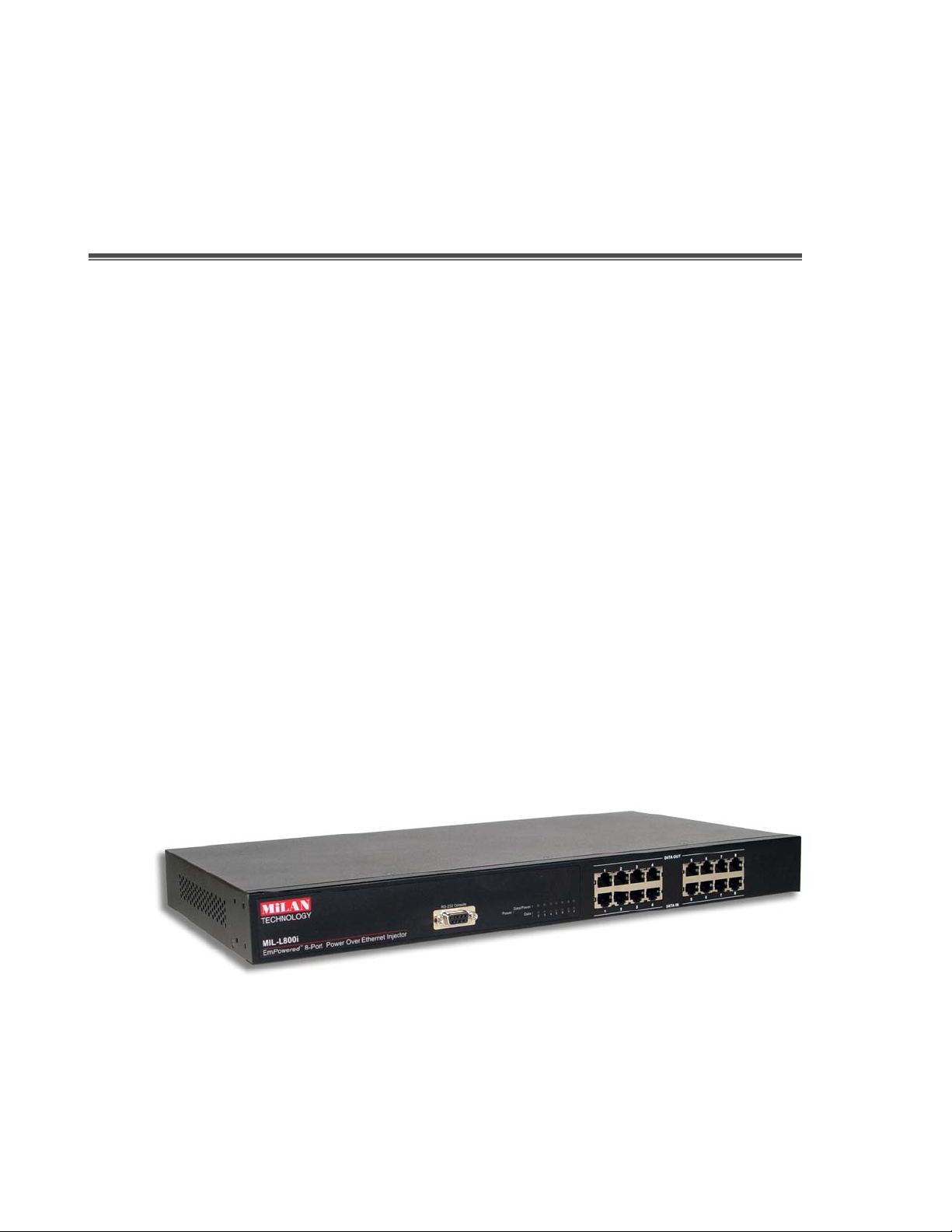
Front Panel
The Front Panel of the MIL-L800i PoE Injector Hub consists of 16x RJ-45 Ethernet ports
(8xData In+8x Data+Power Out), LED indicators, and one console port.
Figure 2-1. The Front panel of 8 port Power over Ethernet Hub
3
Page 7
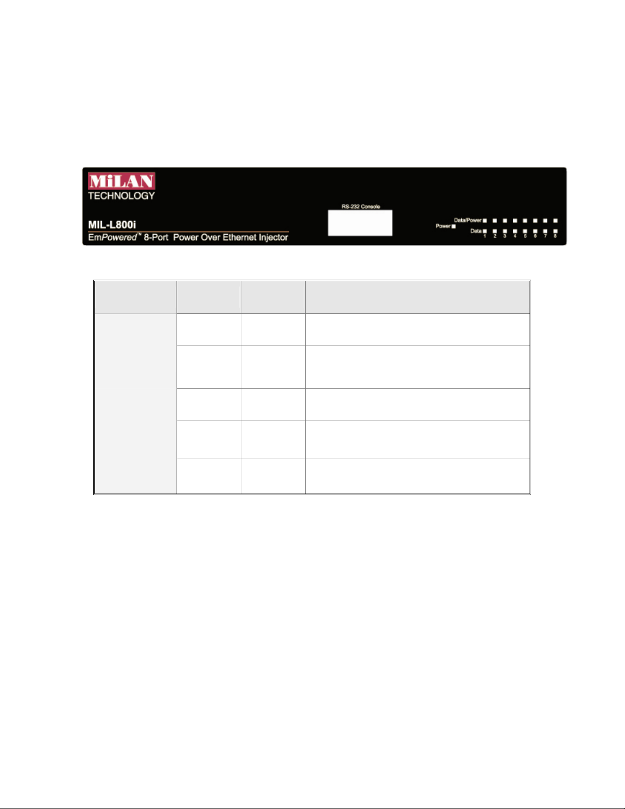
LED Indicators
The LED Indicators gives real-time information of systematic operation status. The
following table provides descriptions of LED status and their meaning.
Figure 2-2. LED indicators
LED Status Color Description
On Green Power is transmitting to the device
Power
Forwarding
Off --
Power is not transmitting to the
device
On Orange Device is overload or short.
Power Off
Blinking Orange It is detecting the PD.
Off -- No device attached.
Table 2-1. The Description of LED Indicators
Rear Panel
The 3-pronged power plug, 2 Ventilation fan and on/off switching are located at the rear
panel of the 8 port Power over Ethernet Hub. The device will work with AC in the range
100-240V AC, 50-60Hz.
4
Page 8

Figure 2-3 Rear panel of the 8 port Power over Ethernet Hub
Power On
Connect the power cord to the power socket on the rear panel of the Switch. The other
side of power cord connects to the power outlet. The internal power supply of the Switch
works with voltage range of AC in the 100-240VAC, frequency 50~60Hz. Check the
power indicator on the front panel to see if power is properly supplied.
Network Application
The Power over Ethernet Hub can provides power to the PD that follow the IEEE 802.3af
standard in the network. It can solve the problem of position limitation. The network
device can be installed in more appropriate position for better performance. The
following figure is an example of network application for Power over Ethernet Hub.
[Note] When the Power over Ethernet Hub connects with the Cisco Aironet 350, please
use cross over cable for connection. For the other brands’ devices, please use
non-cross over cable.
5
Page 9

Co re S wit ch
8x2x9x3x10x4x11x
7x
8x2x9x3x10x4x11x
789101112
123456
7x
1x
C
Ethernet
A
12x
1x
6x
5x
A
12x
AC power
6x
5x
B
Switch
8x2x9x3x10x4x11x
7x
8x2x9x3x10x4x11x
789101112
123456
7x
1x
C
Ethernet
A
12x
1x
6x
5x
A
100M
12x
AC power
6x
5x
B
Powe r o ve r Eth e rn e t Hub
AC power
PC o r
Notebook
Powe r o ve r Eth e rn e t Hub p rovide
po we r t o Pow e re d d e vice
POWERFAULTDA TA ALARM
Pow e r e d De vice , ex: SOHO
sw itc h or W ir ele ss AP
Figure 2-3 Power over Ethernet Hub network application
6
Page 10

3.
Software Utility Installation
Berfore you start to remote configuring PD, please intsall the software utility. Through the
software utility, you can easily to controll the PD that connect with PoE and view the PD
parameter informations. The software utility provides GUI interface and user can easily
to start with it. The software utility supports Windows environment -- Window 98, 2000,
and XP. Please follow the below steps to install the software utility.
1. Insert the software utility CD-ROM into your CD-ROM drive.
2. Run the “setup.exe”.
3. You will see the inst allation screen display.
4. Then, click the “OK” button to go next step. See Figure 3-1.
Figure 3-1
7
Page 11

5. Click the button to start installation. See Figure 3-2.
Figure 3-2
8
Page 12

6. When installation finishes, click “OK” button to finish. See Figure 3-3.
Figure 3-3
7. To run the software utility, go to “Star” Æ “Program” Æ “Power Over Ethernet
series”.
8. If you want to remove the software utility, go to “Star” Æ “Control Panel” Æ
“Remove/ Add application” Æ “Power Over Ethernet series”.
9
Page 13

4.
GUI Management
Connecting to PoE
Connecting the PoE with PC through the console port. Then, connect the PD (Powered
Device) to the port of PoE. Run the software utility and select the COM port form Serial
Link Setup function. You will see the main utility interface as figure 4-1.
Figure 4-1. The GUI management interface
The GUI management is divided into three parts:
System Setup & Control: main system level parameters setup for the POE system.
System Information: display hardware version, firmware version, and utility
version.
10
Page 14

Device Setting: you can save the device configuration to system, down load the
device current configuration to the utility system and enable auto refresh function.
Port Specific Control: each port specific function control and relate parameters
display.
Parametric Information: port parameters information display.
System Setup & Control
Calibrate System: when the system can’t do the port controlling, please remove the
PD device and enable this function to calibrate internal system.
PD Discovery R (ohms): set the PD resistor value range for the system detecting.
The default value range is 19000~26500. You can adjust the upper and lower limit
value when the system can’t detect the PD resistor in the default range. Please refer to
the “Discover R (ohms)” value in Parametric Information section to adjust the upper
and lower limit value. After you have adjusted the upper or lower limit value, please
unplug and then plug in the PD device.
Figure 4-2. System Setup & Control interface
11
Page 15

System Information
Chip Version: display the system chipset version and revision information.
Firmware Version: display the system firmware version.
Utility Version: display the system utility version
Total Port Power (W): total of all the port power that the system provided to PD.
Figure 4-3. System Information interface
12
Page 16

Device Setting
Enable Auto-Refresh:
The system auto refresh in every 2 seconds.
Load fr om Dev ice
utility.
Save to Device
Port Specific Control, please press
configuration into the system.
It allows the system auto refresh the system parameters.
: To get the last configuration value from device to the system
: When you have configured the System Setup & Control and
Save to Device
button to apply the new
Figure 4-4 Device Setting interface
13
Page 17

Port Specific Control
Port Enable: enabling the port. This function is co-responding with “Master Enable”
function.
Bypass Detection: bypass the detection function. Normally the system will try to
detect the 25kΩ resistor in an 802.3af compliant PD device. If the PD doesn’t follow
by IEEE 802.3af standard, you can enable this option to skip the detection on PD.
When you enable this function, the system will not perform the 25Ω resistor
detection for PD and directly transmit the power to PD. This function can be
cooperating with “PD discover R (ohms)” function in System setup & Control section
for non-standard compliant PD device.
[Note] after setting the Bypass Detection function, please unplug and then plug in
the PD device.
Bypass Classification: the system will skip the power classification and directly
transmit the power to PD when this function is enabling. Normally the system will try
to classify the 802.3af compliant PD device by checking the current class level. The
following table is a standard current classification level table.
Note: After setting the Bypass Classification function, please unplug and then plug in
the PD device.
Power Device
Class Usage
0 Default 0.44 12.95 0 4
1 Optional 0.44 3.84 9 12
2 Optional 3.84 6.49 17 20
Power (W)
MIN MAX MIN MAX
Classification Current
(mA)
3 Optional 6.49 12.95 26 30
4 Optional Reserved for future use 36 44
Table of Power Device Classification Levels
14
Page 18

LED Status Indicators: current LED indicator display – green, yellow, and red. The
LED indicator will change depends on the PD status.
¾ Green: It represents PD is connecting with the POE hub system and working
normally.
¾ Yellow: It represents there is no PD connecting with the port.
¾ RED: It represents PD’s power request is over the system support limit or the
cable is short.
Fault Status: display the PD error status message. There are three error status and
explain as following.
¾ Null: It means there is no PD connected or the connected PD device status is
normal.
¾ Overload: It means the current is over the PD current classification limited
(475mA @ 48V DC) that the situation happens over 50msec.
Mode Status: display the PD current operation mode status.
¾ V sample or I sample: It means " Current sample or Voltage sample”. When
PD is detected and current is supplied, the POE hub will keep detecting and
sampling some current or voltage to ensure whether the PD still present on this
port. It is a IEEE 802.3af operating procedure.
¾ R detect: When the port doesn’t connect with any PD, the POE hub will poll
each port and detects the resistor.
15
Page 19

Figure 4-5. Port Specific Control interface
16
Page 20

Parametric Information
Discovery R (ohms): display resistance value.
Port Current (mA): display current value.
Port Voltage (V): display voltage value.
Port Power (W): display watt value.
Class Current (mA): display class current value. When you enable the “Bypass
classification” function, the class current value will not show in here. Please refer to
the following table for output value.
Maximum power of levels at
Class Usage
output of PSE
0 Default 15.4 Watts
1 Optional 4.0 Watts
2 Optional 7.0 Watts
3 Optional 15.4 Watts
4 Reserved for future use Treat as Class 0
Determined Class: display power class. When you enable the “Bypass
classification” function, the class value will not be shown.
Figure 4-6. Parametric Information interface
17
Page 21

5.
Technical Specification
IEEE802.3af Power over Ethernet
Standards
Connector
Power out put
Management
Power over Ethernet mode
IEEE802.3 10Base-T,
IEEE 802.3u 100Base-TX
Data in: 8 x RJ-45, Data pin 1,2,3,6
Data and power out: 8 x RJ-45. Data pin
1,2,3,6 Power pin (V+): 4,5, Power pin (V-): 7,8
Per port DC 48V@350mA (Maximum), Per
system 125Watts (maximum)
Microsoft windows based application for power
management
Mid-Spain
Support Microsoft windows based application
Management utility
System setup and control
Port configuration control
for power management
Plug and play for standard PD and without any
software configuration
System calibrate, IEEE 802.3af resistor range
adjust
Port Disable / Enable
PD detect control (enable/disable)
Classification detect control (enable/disable)
18
Page 22

Null: no PD present or PD status is normal
Fault status detect
Mode status
Parametric information
LED
Power
Overload: current support over 475mA @ DC
48V and over 50 milliseconds
System detects status – I- sample, V-sample
and R-detect
It will show current PD parameters which
include Discover-resistor detected value,
current, voltage, power consumption,
classification current and determined class
System: power
Per port: power Forwarding, power off
AC 100~240V, 50/60 Hz, 130 Watts, IEC
power socket with fuse and power switch
Power consumption
Cooling
Weight
Operating environment
Storage temperature
Humidity Temperature
Dimension
EMI & Safety
130 Watts (maximum)
2 x DC fan
2.7Kg
0℃~45℃, 90%RH
-40℃~70℃, 95% RH
10% ~ 90% (non-condensing)
440mm x 224mm x 44mm (L x W x H)
FCC Class A, CE, UL, cUL
19
Page 23

6.
Appendix
Console Port Pin Assignments
The female DB-9 serial port on the POE hub front panel is used to connect to the switch
for out-of-band console configuration. The web interface configuration program can be
accessed from PC running the system utility program. The pin assignments used to
connect to the serial port are provided in the following tables.
Figure 6-1. DB-9 Console Port Pin Numbers
20
Page 24

DB-9 Port Pin Assignments
EIA Circuit CCITT Signal Description
RxD (Received
BB 104
Data)
TxD
BA 103
(Transmitted
Data)
SGND (Signal
AB 102
Ground)
NOTE: Remaining pins are not used.
Switch’s DB9
DTE Pin #
2 2
3 3
5 5
PC DB9
DTE Pin #
Console Port to 9-Pin DTE Port on PC
Switch’s 9-Pin Serial
CCITT Signal PC’s 9-Pin DTE Port
Port
2 RXD <---------RXD ------------ 3 TxD
3 TXD -----------TXD ----------> 2 RxD
5 SGND -----------SGND ---------- 5 SGND
NOTE: Remaining pins are not used.
21
Page 25

90000429 Rev 1P
 Loading...