

Page 1
Regulatory Approval
•
FCC Class A
•
UL 1950
•
CSA C22.2 Number 950
•
EN60950
CE
•
- EN55022 Class B
- EN50082-1
Canadian EMI Notice
This Class A digital apparatus meets all the requirements of the Canadian Interference-Causing Equipment Regulations.
Cet appareil numerique de la classe A respecte toutes les exigences du Reglement sur le materiel brouilleur du Canada.
European Notice
Products with the CE Marking comply with both the EMC Directive (89/336/EEC) and the Low Voltage
Directive (73/23/EEC) issued by the commission of the European Community Compliance with these directives
implies conformity to the following European Norms:
•
EN55022 (CISPR 22) - Radio Frequency Interference
•
EN50082-1 (IEC801-2, -3, -4) - Electromagnetic Immunity
•
EN60950 (IEC950) - Product Safety
Installation Guide: MIL-C2113 Series
MiLAN Technology warrants to the original consumer or purchaser that each of it’s products, and
all components thereof, will be free from defects in material and/or workmanship for a period of
five years from the original factory shipment date. Any warranty hereunder is extended to the
original consumer or purchaser and is not assignable.
MiLAN Technology makes no express or implied warranties including, but not limited to, any
implied warranty of merchantability or fitness for a particular purpose, except as expressly set
forth in this warranty. In no event shall MiLAN T echnology be liable for incidental or
consequential damages, costs, or expenses arising out of or in connection with the performance
of the product delivered hereunder. MiLAN Technology will in no case cover damages arising
out of the product being used in a negligent fashion or manner.
Trademarks
© 2000 MiLAN, the MiLAN logo and MiLAN Technology are either trademarks or registered
trademarks of Milan , Inc. in the United States and/or other countries. All other
trademarks are the property of their respective holders.
To Contact MiLAN Technology
For prompt response when calling for service information, have the following information ready:
•
Product serial number and revision
•
Date of purchase
Vendor or place of purchase
•
You can reach MiLAN Technology technical support at:
E-mail: support@milan.com
Telephone: +1.408.744.2751
MiLAN Technology
Fax: +1.408.744.2771
Five-Year Limited Warranty
.
LEDs
RJ-45
Connector
SC - Type
Connector
The MIL-C2113 comes equipped with SC-type connectors and supports Fast
Ethernet in both half and full-duplex mode. For network budget constraint,
the MIL-C2113 uses 150 nanoseconds (approximately 30 meters of cable)
during conversion in each direction.
To maximize the fiber cable distance, use one meter of CA T 5 UTP cable
when connecting directly to a node (subject to fiber budget of 16dBm and
collision domain restrictions). In full-duplex environments, use up to 100m
of CAT 5 UTP and:
2Km of multi-mode optical fiber for MIL-C2113;
15Km of single-mode optical fiber for MIL-C2113-15;
40Km of single-mode optical fiber for MIL-C2113-40;
70Km of single-mode optical fiber for MIL-C2113-70;
100Km of single-mode optical fiber for MIL-C2113-100.
Page 2
M ulti-mode fi ber
1300nm wavelength
•
62.5/125 micron diameter
•
4 dBm launch power
-1
•
1 dBm receive sensiti vity
-3
•
Si
ngle-mode fiber (70Km)
1300nm wavelength
•
9/125 micron diameter
•
-4 d
Bm launch pow er
•
7 dBm receive sensiti vity
-3
•
Si
ngle-mode fiber (15Km)
1300nm wavelength
•
9/125 micron diameter
•
Bm launch pow er
-8 d
•
1 dBm receive sensiti vity
-3
•
Single-mode fi ber (100Km)
1300nm wavelength
•
9/125 micron diameter
•
Bm launch pow er
-3 d
•
7 dBm receive sensiti vity
-3
•
Single-mode fi ber (40Km)
1300nm wavelength
•
9/125 micron diameter
•
Bm launch pow er
-5 d
•
4 dBm receive sensiti vity
-3
•
SC-Type
Connectors
4-pin DIP Switch
4
3
2
1
LEDs
RJ-45 Female
Connector
4
5
3
2
MDI-X
Pin 1= RX+
Pin 2= RXPin 3= TX+
Pin 6= TX-
MDI-X/MD
Switch
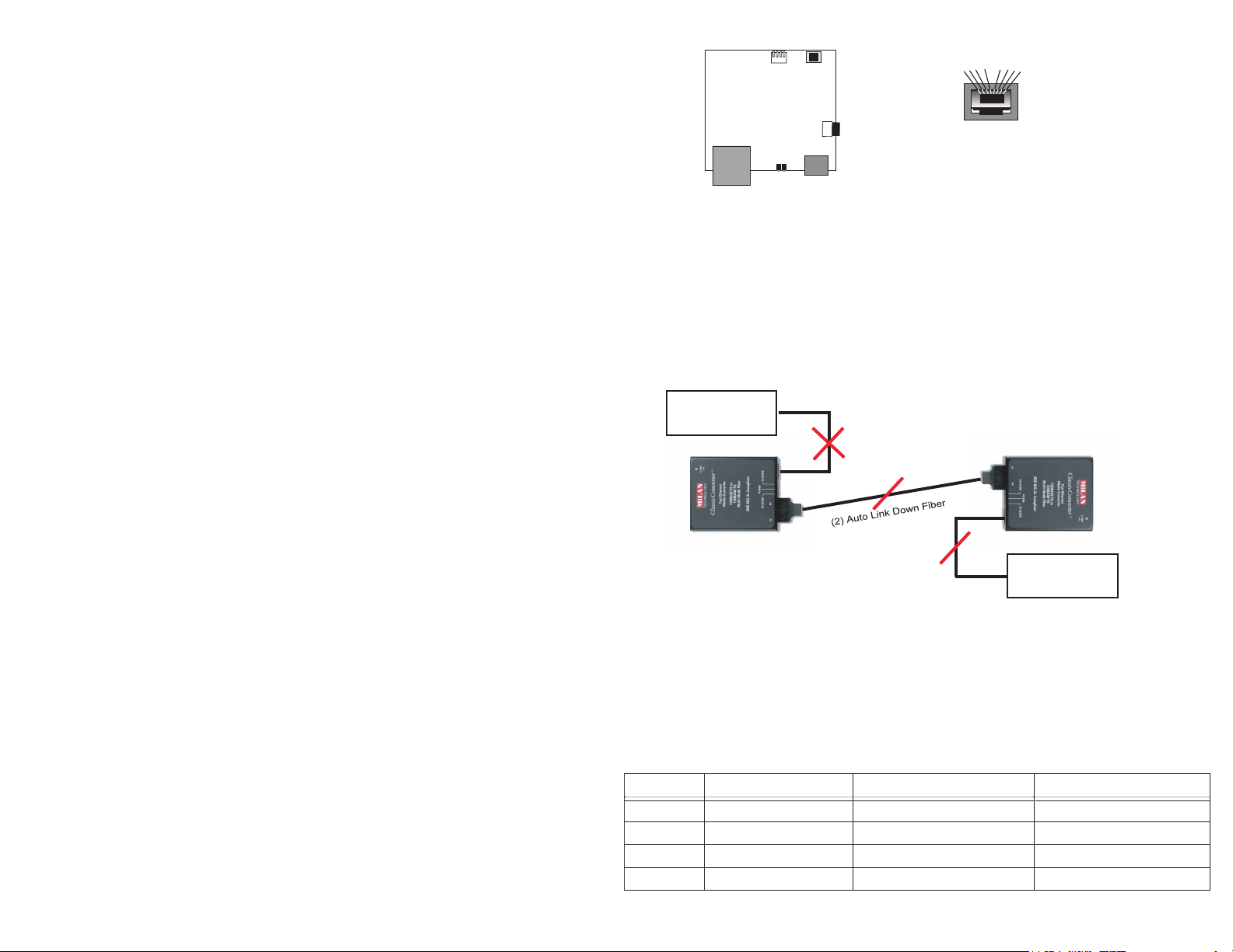
Figure 1. Inside of the MIL-C2113 and
RJ-45 Pinouts
1
6
7
8
MDI
Pin 1= TX+
Pin 2= TXPin 3= RX+
Pin 6= RX-
Installation
1. Attach a UTP cable from the network to the RJ-45 port.
(Use screened UTP cabling for CISPR 22 class B installation.)
2. Cross-connect the fiber cables: Attach both fiber cables
TX to RX and RX to TX from the fiber network cabling to the
ST-type connectors on the MIL-C2113.
3. Apply power to the unit:
A. Insert the power adapter’s receptacle into the power plug.
B. Insert the power adapter into a wall outlet.
Diagnostic LEDs and Conditions Indicated
There are five LEDs, including power and:
TX/ACTIVE: Receiving packets from the 100BASE-TX port.
•
FX/ACTIVE: Receiving packets from the 100BASE-FX port.
•
TX/LINK: An active connection on the 100BASE-TX port.
•
FX/LINK: An active connection on the 100BASE-FX port.
•
MDI-X/MDI Switch
The MDI-X/MDI switch allows for quick configuration
of the 100BASE-TX port. Cables used when the switch is
in the MDI-X position (the “left” position:
For a hub/repeater, use a swap cable (pins are
•
connected 1 to 3, 2 to 6, 3 to 1, and 6 to 2).
For a workstation/PC, use a straight-through cable
•
(pins are connected 1 to 1, 2 to 2, 3 to 3, and 6 to 6).
Cables used when the switch is in the MDI position (the
“right” position):
For a hub/repeater, use a straight-through cable (pins
•
are connected 1 to 1, 2 to 2, 3 to 3, and 6 to 6).
For a workstation/PC, use a swap cable (pins are
•
connected 1 to 3, 2 to 6, 3 to 1, and 6 to 2).
Note: The MIL-C211X media converters operate at full duplex.
Therefore, when connecting the Copper UTP port, be sure to force the
link partner to 100 Full duplex. Failure to force link partner may result
in a duplex mismatch when connecting to an auto negotiating device.
Link Sentry Configuration
The Link Sentry feature on the MIL-C2113 is configured through
a 4-position DIP switch (refer to Table 1).
Link Sentry is a troubleshooting feature that allows MiLAN media converters
to monitor link states on both fiber and copper ports in the event of a physical link down. If a link down is detected, the converter will automatically
notify the end device of the link down by disabling the TX signal of the
neighboring port. (see Figure 2.)
End Node A
(1) Link Down Node A
(3) Auto Link Down Node B
Figure 2. Link Sentry Back to Back Configuration
End Node B
Note: When connecting two MIL-C211X series converters back to
back via fiber, Dip Switches 1 & 2 should be in the “up” and 3 & 4
should be in the “down” position.
The following table displays the Link Sentry dip switch settings needed when the
MIL-C211X is installed in a single media converter environment (not back to back).
Tabl
e 1. Single Converter Link Sentry Settings
Switch
1
2
3
4
UP Down
Fiber TX to RX Link Sentry Disabled
N/A
Copper to Fiber Link Sentry Disabled
Fiber to Copper Link Sentry Disabled
Fiber TX to RX Link Sentry Enabled
N/A
Copper to Fiber Link Sentry Enabled
Fiber to Copper Link Sentry Enabled
Fiber TX link down causes Fiber RX to link down
Copper link down causes Fiber link down
Fiber link down causes Copper link down
Function
Reserved, must remain in up position
 Loading...