

Page 1
Regulatory Approvals
FCC Class A
UL 1950
CSA 22.2 No. 950
EN60950
CE
– EN55022 Class B
– EN50082-1
Canadian EMI Notice
This Class A digital apparatus meets all the requirements of the Canadian Interference-Causing
Equipment Regulations.
Cet appareil numérique de la classe A respecte toutes les exigences du Règlement sur le matériel
brouilleur du Canada.
European Notice
Products with the CE Marking comply with both the EMC Directive (89/336/EEC) and the
Low Voltage Directive (73/23/EEC) issued by the commission of the European Community.
Compliance with these directives implies conformity to the following European Norms:
EN55022 (CISPR 22) - Radio Frequency Interference
EN50082-1 (IEC801-2, IEC801-3, IEC801-4) - Electromagnetic Immunity
EN60950 (IEC950) - Product Safety
Five-Year Limited Warranty
MiLAN Technology warrants to the original consumer or purchaser that each of its products,
and all components thereof, will be free from defects in material and/or workmanship for a
period of five years from the original factory shipment date. Any warranty hereunder is
extended to the original consumer or purchaser and is not assignable.
MiLAN Technology makes no express or implied warranties including, but not limited to, any
implied warranty of merchantability or fitness for a particular purpose, except as expressly set
forth in this warranty. In no event shall MiLAN Technology be liable for incidental or
consequential damages, costs, or expenses arising out of or in connection with the
performance of the product delivered hereunder. MiLAN Technology will in no case cover
damages arising out of the product being used in a negligent fashion or manner.
Trademarks:
The MiLAN logo and MiLAN Technology are registered trademarks of MiLAN Technology
in the United States and/or other countries.
To Contact Technical Support:
For prompt response when calling for service, have the following information ready:
- product serial number
- date of purchase
- vendor or place of purchase
You can reach MiLAN Technology technical support at:
- Email: support@milan.com
- Telephone: +1.408.744.2775
- Fax: +1.408.744.2793
MiAN Technology
1329 Moffett Park Drive
Sunnyvale, CA 94089
United States of America
Telephone: +1.408.744.2775
Fax: +1.408.744.2793
http://www.milan.com
info@milan.com
Installation Guide MIL-185C/MIL-195C
MIL-185C/MIL-195C
TIVE
TIVE
R
TIVE
TWIST
5VDC
Ethernet
10BASE-FL
MIL-195C
500mA
ATM Twist
Model: MIL 195
UTP
to
Fiber
ATM
Single-Mode
CONVERTER
FCC PART 15 CLASS A COMPLIANT
5VDC
UTP ACTIVE
UTP AC
TIVE
P
O
WE
R
F
I
B
E
R AC
TIVE
RXTX
-X/MDI
MDI
AT M
ATM Fiber/UTP Converter
MIL-185C
ATM Twist
Model: MIL 185
UTP AC
UTP
UTP AC
to
P
O
FCC PART 15 CLASS A COMPLIANT
RXTX
WE
F
I
B
E
R AC
Fiber
ATM
Multi-Mode
CONVERTER
Installation Guide
This guide includes the following information:
"Introduction" on page 2
"Installation" on page 3
"Configuration Option" on page 4
"Specifications" on page 7
© Copyright 2002 MiLAN Technology Printed in the USA P/N: 90000011 Rev. G
Page 2
About this Manual
Installation Guide MIL-185C/MIL-195C
Operating Conditions
This manual covers both the MIL-185C and the MIL-195C
media converters.
The terms “converter” or “device” are used throughout
the document to describe either the MIL-185C or the
MIL-195C.
Introduction
The MIL-185C and the MIL-195C are compact, physical
media converters that allow the user to convert signals
between ATM fiber optic cabling in either multi-mode or
single-mode, and UTP cabling. Both converters support
OC-3 (155Mbps) speeds.
Features
• Fiber budget sufficient to drive 2 km for multi-mode
or 15 km for single-mode fiber
• One SC-type single-mode (MIL-195C) or one SC-type
multi-mode (MIL-185C) connector
Table 1: Recommended Operation Conditions
Parameters Minimum Maximum
Operating Temperature +5° C 40° C
Humidity: non-condensing 10% 95%
Signal Output Load 35 ohm 75 ohm
Supply Voltage 4.75 V 5.25 V
Power Supply
External power is required. The device draws 900 mA at
normal operation in room temperature of 25° C.
• Domestic: 110 V AC wall mount power supply.
• International: 220 V AC power supply with IEC
receptacle.
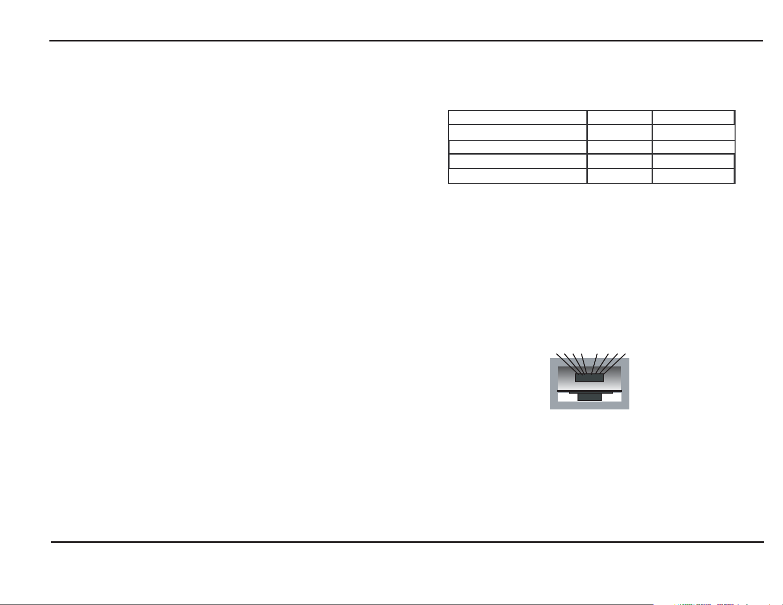
Connectors
1 2 3 4 5 6 7 8
• One shielded RJ-45 UTP connector
• External power supply
• Diagnostic LEDs
• Small form factor
2
Figure 5. RJ-45 Connector
RJ-45 Pinouts
• Pin 1 = Transmit Data +
• Pin 2 = Transmit Data -
• Pin 7 = Receive Data +
• Pin 8 = Receive Data -
7
Page 3

MIL-195C
The MIL-195C converter supports full-duplex ATM
Fiber/UTP links. For fiber budget constraints, the MIL 195C has a launch power of -19 db and a receive
sensitivity of -30 db (using a 1300 nm class 1 laser). In a
full-duplex environment, up to 100m of CAT 5 UTP and
15km single-mode fiber can be used.
Installation Guide MIL-185C/MIL-195C
Installation
To install either converter:
1. Attach the CAT 5 UTP cable from the network to the
RJ-45 port on the device.
Note: Use screened CAT 5 UTP cable for CISPR-22 class B installation.
ATM Twist
Model: MIL 195
UTP
to
Fiber
ATM
Single-Mode
CONVERTER
FCC PART 15 CLASS A COMPLIANT
UTP ACTIVE
UTP ACTIVE
POWER
FIBER ACTIVE
RXTX
Figure 4. MIL-195C
Specifications
Storage Temperature
5VDC
2. Attach the fiber network cable connectors to the
connectors marked “RX” (Receive) and “TX”
(Transmit).
3. Connect the power receptacle from the wall adapter
to the unit.
4. Verify that the power LED illuminates.
5. Verify that both the UTP and the FIBER active LEDs
also illuminate when all cables are attached.
Important notice: This device is set to half duplex mode at the factory. If you are
experiencing excessive collision errors or CRC errors, then you
must force full duplex mode operation on the connecting
device(s) before you power up the MiLAN device(s).
Diagnostic LEDs
• UTP ACTIVE: Illuminates when the device receives a
valid signal from the device connected to the UTP port
• POWER: This LED illuminates when the device is
powered up
• Minimum: -25° C
• Maximum: 75° C
• FIBER ACTIVE: Illuminates when the device receives a
valid signal from the device connected to the fiber port.
6
3
Page 4

Configuration Options
Installation Guide MIL-185C/MIL-195C
Special Notes
The following two figures display the typical network
configuration for the converters.
RJ-45
connector
ATM Twist
Model: MIL 185
Multi-Mode
CONVERTER
Fiber
cabling
UTP
to
Fiber
ATM
FCC PART 15 CLASS A COMPLIANT
UTP A
UTP ACTIVE
P
O
W
F
I
BE
RXTX
CTIVE
E
R
R
ACTIVE
5 VDC power
connector
5VDC
Power
UTP cabling
Switching hub
Figure 1. Fiber Network to Switching Hub
Power
RJ-45
connector
ATM Twist
Model: MIL 185
Multi-Mode
CONVERTER
Fiber
cabling
UTP
to
Fiber
ATM
FCC PART 15 CLASS A COMPLIANT
UTP A
UTP ACTIVE
P
O
F
I
RXTX
CTIVE
W
E
R
B
E
R ACTIVE
5 VDC power
connector
5VDC
UTP cabling
Ethernet port
MIL-185C
The MIL-185C converter supports full-duplex ATM
Fiber/UTP links. For network budget constraints, the
MIL-185C has a launch power of -19 db and a receive
sensitivity of -31 db (using a 850 nm class 1 laser). In a
full-duplex environment, up to 100m of CAT 5 UTP and
2km of multi-mode fiber may be used.
5VDC
ATM Twist
Model: MIL 185
UTP
to
Fiber
ATM
UTP ACTIVE
UTP ACTIVE
POWER
FIBER ACTIVE
Multi-Mode
CONVERTER
FCC PART 15 CLASS A COMPLIANT
RXTX
Figure 3. MIL-185C
Figure 2. Fiber Network to Remote—Full-Duplex Workstation
4
5
 Loading...