

Page 1
The TRANSITION Networks slide-in-module 10Mb/s Ethernet media converters, C/FSM-MM-05, which is designed to be installed in the TRANSITION Networks Media
Conversion Center,
E-MCC-1600, connects 1300nM singlemode fiber-optic cable to
850nM multimode fiber-optic cable.
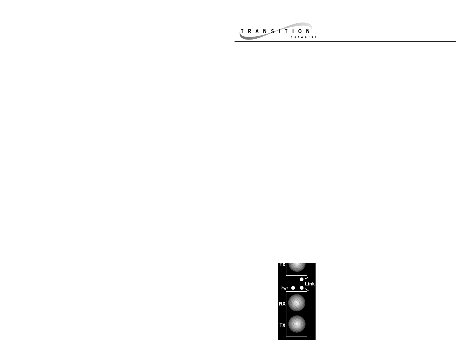
The F-SM-MM-05 media converter provides an ST fiber type RX (receive) and TX
(transmit) connector to 1300nM singlemode fiber-optic cable and an ST fiber type RX
and TX connector to 850nM multimode fiber-optic cable. Fiber’s low signal loss and
high resistance to radio frequency noise allow extended distances between devices
(up to 2 kilometers for multimode, up to 20 kilometers for singlemode).
The media converter functions in half-duplex mode or, when connected to devices
capable of full-duplex connectivity, in full-duplex mode.
10Mb/s Ethernet™ Single Mode/Multimode
Slide-In-Module Media Converter
C/F-SM-MM-05
USER’S GUIDE
Compliance Information
UL Listed
C-UL Listed (Canada)
CISPR/EN55022 Class A
FCC Regulations
This equipment has been tested and found to comply with the limits for a class A digital device, pursuant
to part 15 of the FCC rules. These limits are designed to provide reasonable protection against harmful
interference when the equipment is operated in a commercial environment. This equipment generates,
uses, and can radiate radio frequency energy and, if not installed and used in accordance with the
instruction manual, may cause harmful interference to radio communications. Operation of this
equipment in a residential area is likely to cause harmful interference, in which case the user will be
required to correct the interference at the user’s own expense.
Canadian Regulations
This digital apparatus does not exceed the Class A limits for radio noise for digital apparatus set out on
the radio interference regulations of the Canadian Department of Communications.
European Regulations
Warning
This is a Class A product. In a domestic environment this product may cause radio interference in which
case the user may be required to take adequate measures.
Copyright Restrictions
© 1998, 1999 TRANSITION Networks.
All rights reserved. No part of this work may be reproduced or used in any form or by any means –
graphic, electronic, or mechanical – without written permission from TRANSITION Networks.
Trademark Notice
All registered trademarks and trademarks are the property of their respective owners. 33047.B
MEDIA CONVERTER TECHNICAL SPECIFICATIONS
Environment Temperature: 0-40°C (32° to 104° F )
Humidity 10-90%, non condensing
Altitude 0-10,000 feet
Warranty Five years
P(o)w(e)r Illuminated green LED indicates
connection to external AC power.
Link Steady green LED indicates that fiber
link is connected properly.
850nm Multimode 1300nm
Minneapolis, MN 55344 USA
Status LEDs
Page 2

1. Is the power LED on the media converter illuminated?
NO
• Is the Slide-In-Module properly connected to the Media Conversion Center chasis
backplane?
• Is the Power Supply Module properly connected both to the Media Conversion
Center chasis backplane and to the AC outlet?
• Contact Technical Support at (800) 260-1312/ (800) LAN-WANS.
YES
• Proceed to step 2.
2. Is the multimode fiber Link LED illuminated?
NO
• Check fiber cables for proper connection.
• Verify that TX and RX cables on media converter are connected to RX and TX
ports, respectively, on the other device.
• Refer to Tech Tips available at: http://www.transition.com
• Contact Technical Support at (800) 260-1312/ (800) LAN-WANS.
YES
• Proceed to step 3.
3. Is the singlemode fiber Link LED illuminated?
NO
• Check fiber cables for proper connection.
• Verify that TX and RX cables on media converter are connected to RX and TX
ports, respectively, on the other device.
YES
• Contact Technical Support at (800) 260-1312/ (800) LAN-WANS.
Troubleshooting
If the singlemode to multimode fiber-optic media converter fails, ask the following:
SINGLEMODE
Fiber Optic Cable Recommended: 9/125 µm singlemode fiber
Fiber Optic Transmitter Power: Average: -16 dBm
Fiber Optic Receiver Sensitivity: Average: -33 dBm
Wavelength: 1300nM
Bit error rate: ≤10
-9
Maximum Cable Distance: 5-20 kilometers
MULTIMODE
Fiber Optic Cable Recommended: 62.5 / 125 µm multimode fiber
Optional: 100 / 140 µm multimode fiber
85 / 125 µm multimode fiber
50 / 125 µm multimode fiber
Fiber Optic Transmitter Power: Average: -15 dBm
Fiber Optic Receiver Sensitivity: Average : -33 dBm
Wavelength: 850nM
Bit error rate: ≤10
-10
Maximum Cable Distance: 2 kilometers (6,600 feet)
NOTE: This product is NOT a repeater. Therefore, maximum
distances depend on specific characteristics of the installation.
The full distances of BOTH singlemode and multimode fiber
shown MAY NOT be supported in the same installation.
Fiber Optic Cable Specifications
Installing Slide-In-Module(s)
CAUTION: Wear a grounding device and observe electrostatic discharge precautions when
installing Media Converter Slide-in-Module(s) in the 16-Slot Media Conversion Center. Failure
to observe this caution could result in damage to, and subsequent failure of, the Media
Converter Slide-in-Module(s).
NOTE: Media Converter Slide-in-Modules can be installed in any installation slot, in any order.
To install the Media Converter Slide-in-Module in the E-MCC-1600 chassis:
1. Remove Media Converter Slide-in-Module protective plate from selected installation slot by
removing two screws that secure plate to front of E-MCC-1600. Retain one installation
screw.
2. Carefully slide Media Converter Slide-in-Module into installation slot, aligning Media
Converter Slide-in-Module with installation guides.
NOTE: Ensure that the Media Converter Slide-in-Module is firmly seated against the
backplane.
3. Secure Slide-in-Module by installing retained installation screw.
FIBER OPTIC CABLE CONNECTIONS
• Be certain that the correct mode and wavelength fiber cable is used
BOTH for single-mode and for multimode fiber cable installations.
• Verify that TX and RX cables on media converter are connected to RX
and TX ports, respectively, on the other device.
C/F-SM-MM-05
 Loading...