

MILANDR MILUR 107 Operation Manual
Milandr, Inc.
Milur 107 Operation Manual
Operational Manual for Milur 107 Smart Meter
Page 1 of 16
MILUR 107 ELECTRIC METER OPERATION
MANUAL
Purpose: This manual, intended for studying Milur 107 Smart Electric Meter (hereinafter - the Meter) and
the main guiding document during operation (Installation, Usage, technical information, and maintenance).
The Instruction Manual Contains:
• Description of the Meter and its components;
• Technical Specifications and other information necessary to ensure capabilities of the meter;
• Guidance for dealing with the meter;
• Safety Information and best practices;
• Installation Instructions;
• Manual & Remote operation details;
Note:
The manufacturer is continuously upgrading the meters. The meters may have minor differences
not reflected in the operation manual.

Milandr, Inc.
Milur 107 Operation Manual
Operational Manual for Milur 107 Smart Meter
Page 2 of 16
TABLE OF CONTENTS
1. Product Description
2. Technical Details
3. Safety Information
4. Conditions of Use
5. Environmental Considerations
6. Installation Procedure
7. Manual Operation
8. Remote Operation
9. Measures to prevent unauthorized access
10. Tariff Schedule
11. Load Control
12. Maintenance
13. Software Identification

Milandr, Inc.
Milur 107 Operation Manual
Operational Manual for Milur 107 Smart Meter
Page 3 of 16
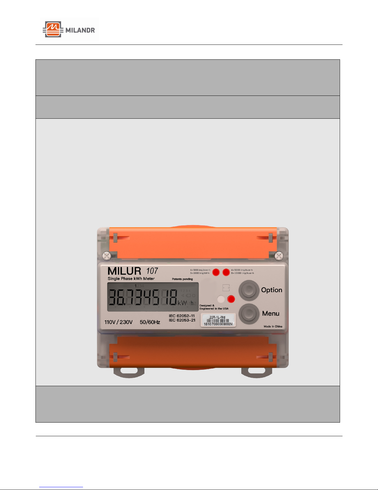
MILUR 107 SMART ELECTRIC METER
Product Description
Description
The Milur 107 is a single-phase smart meter, ideal for measuring
electrical energy consumption. The Meter is direct pass-through, so
it does not require current transformers. It is equipped with a builtin ARM microcontroller and contains a variety of interfaces for
exchanging information with external devices.
The meter is designed to account for active and reactive electrical
energy in two-wire networks of alternating current with a rated
voltage of 110V/230V and frequency 50/60 Hz.
The basic (max) load current is 5 (80) A.
The Meter, depending on its design, is made for both indoor and
outdoor applications. The outdoor enclosures are protected by IP51
and IP54 protection.
A Meter with reduced terminal covers requires additional protection
from direct water ingress.
The measuring unit of the outdoor meter has an IP20 degree of
protection. The Meter is intended for the organization of one and up
to four tariffs of differentiated accounting, both by time of day and
by the level of consumed electricity and power.
Electrical Energy Consumption is shown on the LED (liquid crystal
display) screen on the front of the meter.
The meter has two pulse outputs galvanically separated from the
network for recording active and reactive electrical energy. The
meter can be operated both autonomously or as part of an
automated system of commercial metering of electric power of
ASKUE, with a pre-established program and the possibility of setting
(correcting) the corresponding tariff schedule.
Meter Modifications
The Meter can be equipped with a multitude of modifications, including:
- Additional communication interface (RS-485, PLC, PLC.G3, RF868, ZigBee);
- Hardware load disconnection;
- Additional current sensor in the "zero" wire;
Milandr, Inc.
Milur 107 Operation Manual
Operational Manual for Milur 107 Smart Meter
Page 4 of 16
MILUR 107 SMART ELECTRIC METER
Technical Details
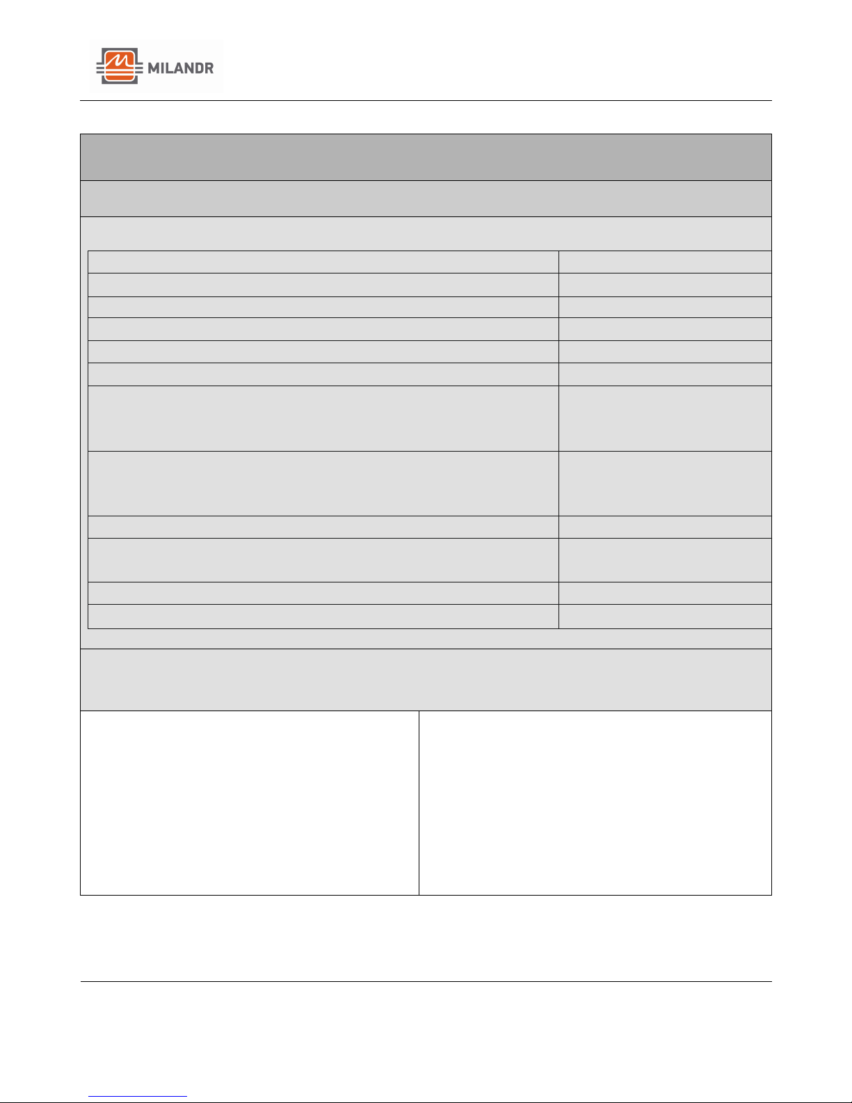
Specifications:
Accuracy Class for active energy
1
Accuracy Class for reactive energy
2
Rated Voltage, V
110 / 230
Absolute limits of working voltage, V
0-265
Current, A
5 (80)
Nominal Frequency, Hz
50/60
Starting current (sensitivity) (no less than), A
- active energy
- reactive energy
0.02
0.025
Operating Temperature range, °F
- indoor Installation
- outdoor Installation
-40 to +158
-58 to +158
Number of tariffs
Up to 4
Accuracy of the build-in clock with the meter on at standard
temperature, s/day (no less than)
±0.5
Average Error-free runtime, hours
220000
Average meter lifetime, years
30
Features:
Reliability and Quality:
MDR32F23QI Chip with 32-bit RISC-core
Cortex-M0
Protection Against Theft:
Electronic log of tamper attempts
Mounting:
DIN Rail Mounting
Fire Safety:
Made of non-combustible Materials
Operating Temperature:
Operates between -40 °F and +158 °F

Milandr, Inc.
Milur 107 Operation Manual
Operational Manual for Milur 107 Smart Meter
Page 5 of 16
MILUR 107 SMART ELECTRIC METER
Safety Information
Safety Information
1. Before operation, it is necessary to familiarize yourself with the
operational documentation of the meter.
2. All work regarding the installation, maintenance and repair of the
meter should be done by persons who have received safety training
and who have worked with a voltage of up to 1000 V.
3. All work related to the installation of the meter must be carried
out on a disconnected network. The circuit breaker should be easily
accessible, located in the immediate vicinity of the meter and
included in the installation of the electrical wiring of the facility.
NOTE - Installation should always be performed by a qualified electrician.
The bus wire and interface connecting diagrams are printed inside the
covers.
Please contact us with any additional installation or maintenance
questions; The detailed specifications, installation and programming
instructions are available online at: www.milur.com
Conditions of Use
1. The voltage applied to the meter must not exceed 265V.
2. The current in the meter's series circuit must not exceed the
specified maximum value of 80 A.
3. Remove the meter from its packaging and perform an external
inspection.
4. Make sure that there is no visible damage to the body or
protective covers for the terminal blocks. Check for the
presence and quality of the seals.
5. Install the meter at the place of operation, remove the
protective covers of the terminal blocks and connect the
voltage and current circuits in accordance with the scheme on
the protective cover.
NOTE - The connection of the internal installation meter to the mains must be
carried out via switch in the immediate vicinity of the meter in an easily accessible
place for the operator. Th e switch must be mark ed as a trip device for the meter.
ATTENTION: connection of voltage and current circuits should be carried out with
the power supply de-energized.
 Loading...