

Page 1

APPROVED EUROPEAN POWER CORD SET
Embossed Alternative Wire
Harmonization Color Codes
Approval Organization Marking Blk Red Ylw
Belgium:Comite
Electrotechnique Beige (CEBEC) CEBEC-HAR 10 30 10
Verband Deutscher Elektrotechniker
(VDE)e, V., Prufstelle VDE-HAR 30 10 10
Technique de l’Electricite (UTE) UTE-HAR 30 30 10
Institute del Marchio Qualita IEMMEQU-HAR 10 30 50
British Approvals Service For
Electric Cables (BASEC-HAR) BASEC-HAR 10 10 30
N.V. tot Keuring van Electro-
technische Matarialien (KEMA) KEMA-KEUR-HAR 10 30 30
Svenska Elecktriska (SMEKO) SMEKO-HAR 10 10 50
Osterreichnischer Verband ful
Electrotechnik (OVE) OVE-HAR 30 10 50
Danmark Elektriske
Materielkontroll (DEMKO) DEMKO-HAR 30 10 30
Institute for Industrial Research
and Standards (IIRS) IRS-HAR 30 30 50
Norges Elektriske
Materielkontroll (NEMKO) NEMKO-HAR 10 10 70
National Standards Authority of
Ireland (NSAI) NSAI-HAR 30 30 50
D-
LAN Master
LAN Master TR16
16 Port
Active Retiming Hub
User’s Guide
Model #: TR-TP-HB-1600
Manual 7348.A
D
Page 2

TECHNICAL SPECIFICATIONS
Cable Type and Distance
There are 18 shielded RJ-45 ports located on the front of the unit.
Either 22, 24, or 26 AWG cable is recommended.
Cable
Catagory Speed Max-Lobe Length* Max-RI\RO Length*
UTP 3 16Mbps 100 meters 150 meters
UTP 5 16Mbps 300 meters 300 meters
STP 5 16Mbps 400 meters 400 meters
UTP 3 4Mbps 300 meters 300 meters
UTP 5 4Mbps 500 meters 500 meters
STP 5 4Mbps 500 meters 500 meters
*Distances as tested with IBM Token Ring and SMC Token Elite Cards.
Other cards guaranteed to 100 meters per 802.5 specification.
Case Dimensions
Height 2” (5cm), Width 19” (48cm), Depth 13“ (33cm).
Interface Connections
16 Lobe ports, 1 Ring Out (RO) port, 1 Ring In (RI) port.
Operating Environment
Temperature: 32° to 122° F (0° to 50° C)
Humidity: 5% to 90% non-condensing
Altitude: 0 to 10,000 feet (max.)
Universal Power Supply
AC Input: 85 - 265 VAC at 47 - 63 Hz. Rated at 40 watts max.
Power Cord
TN
PN Requirement Location
3344 120 volts, 60 hertz USA/Canada/Mexico
3344 100 volts, 50-60 hertz Japan
3347 230 volts, 50 hertz Europe
3348 240 volts, 50 hertz Australia
3349 240 volts, 50 hertz United Kingdom
C
1 INTRODUCTION
A. Technical Support
B. Requirements
2 OVERVIEW OF THE LAN Master TR16
A. Features
B. Description of the Hardware
C. Function of LED’s
D. Switches
3 INSTALLING THE HARDWARE
A. Installation Considerations
B. Pin Assignments for the Twisted Pair Cable Connector
C. Attaching the LAN Master TR16 to the Rackmount Frame
D. Attaching the Twisted Pair Cable
E. Replacing the Fuse
A POLICY AND PROCEDURE
A. Limited Warranty
B. Limitations and Exclusions
C. Return Procedure
D. Restocking Fee
B REGULATION AND REGISTRATION
Compliance Information
FCC Regulation
Canadian Regulation
Copyright Restrictions
Trademark Notice
C TECHNICAL SPECIFICATIONS
Cable Type and Distance
Case Dimensions
Interface Connections
Operating Environment
Universal Power Supply
D APPROVED EUROPEAN POWER CORD SET
Table Of Contents
Page 3

REGULATION AND REGISTRATION
Compliance Information
UL Listed
FCC Regulations
This equipment has been tested and found to comply with the limits for a
Class A digital device, pursuant to Part 15 of the FCC Rules. These limits are
designed to provide reasonable protection against harmful interference when
the equipment is operated in a commercial environment. This equipment
generates, uses, and can radiate radio frequency energy and if not used in
accordance with the instruction manual, may cause harmful interference to
radio communications. Operation of this equipment in a residential area is
likely to cause harmful interference in which case the user will be required to
correct the interference at his own cost.
Canadian Regulations
This digital apparatus does not exceed the Class A limits for radio noise for
digital apparatus set out on the Radio Interference Regulations of the Canadian
Department of Communications.
Copyright Restrictions
© 1994 TRANSITION Networks, Inc.
All rights reserved. No part of this work may be reproduced or used in any
form or by any means- graphic, electronic, or mechanical- without written
permission from TRANSITION Networks, Inc.
Trademark Notice
All registered trademarks and trademarks are the property of their respective
owners. Technical information in this document is subject to change without
notice.
Regulation And Registration
B-1 LAN Master TR16 LAN Master TR16
B
INTRODUCTION
The intended audience for this user’s guide is network installers
and managers. This manual assumes basic familiarity with network
concepts and protocols.
A. Technical Support
TRANSITION Networks is committed to providing customers with a
high quality product along with excellent technical support. Please
feel free to call us with technical questions or suggestions. Contact
your local TRANSITION Networks (TN) distributor or call us directly.
Direct numbers are listed below:
TN Main phone numbers: (612) 941-7600
(800) 325-2725
TN Technical Support number: (800) 260-1312
TN Fax number: (612) 941-2322
TN Bulletin Board: (612) 941-9304
B. Requirements
The following are included with each LAN Master™ TR16. Compare
the shipment to the invoice received.
• LAN Master™ TR16 unit
• Power cord
• This User’s Guide
1
Page 4

A-3 LAN Master TR16 LAN Master TR16
OVERVIEW OF THE LAN Master TR16
The LAN Master TR16 sixteen Port Active Media Hub is a standalone,
active retiming concentrator with secondary backup path.
It has 16 lobe ports plus one RI, one RO port and an internal power
supply. The LAN Master TR16 unit supports both 4 and 16 Mbps and
it has per port retiming functions.
IMPORTANT
This product is designed to support an Active Retime environment
with HOT SWAP capability. An active hub can be added or removed
without bringing the network down.
In order to support Hot Swap Capability when connecting to Passive
Hubs (Ex. IBM8228), the following steps must be taken in sequence:
When adding a passive hub to the LAN Master’s RI port:
• Plug in cable between RI and RO of the passive hub
• Switch the LAN Master “Ring In” switch to “Passive” position.
When removing a passive hub from the LAN Master’s RI port:
• Switch the LAN Master “Ring In” switch to ”Active” position
• Disconnect cable between RI and RO of the passive hub.
When adding a passive hub to the LAN Master’s RO port:
• Plug in cable between RO and RI of the passive hub
• Switch the LAN Master “Ring Out” switch to “Passive” position.
When removing a passive hub from the LAN Master’s RO port:
• Switch the LAN Master “Ring Out” switch to ”Active” position
• Disconnect cable between RO and RI of the passive hub.
When connecting LAN Master to external RI/RO IBM-type Data
Connector, through converter:
• Switch the LAN Master “Ring Out” switch to “Passive” position
• Switch the LAN Master “Ring In” switch to “Passive” position
2
Overview Of The LAN Master TR16
2-1
The sole purpose of this remedy shall be provided the customer with the replacement or
repair of non-conforming goods in the manner described in this Warranty statement. This
exclusive remedy shall not be deemed to have failed of its essential purpose so long as TN
is willing and able to repair or replace the defective item(s) or refund the purchase price.
TN reserves the right to inspect products claimed to be defective under warranty either at
the customer’s location or at TN’s plant. TN assumes no liability for liability charges
incidental to the adjustment, service, repairing, removal or replacement of the product, or
other costs, or the expense of repairs made outside of its factory, except when made with
TN’s prior written consent. Additionally, Transition Networks reserves the right to charge for
all testing and shipping incurred, if after testing, a return is classified as “No Problem
Found”.
TN’s total liability in connection with the products and their installation to all persons and
from all causes in the aggregate, whether in contract, tort, or strict liability, shall not exceed
the amount paid to TN for the product directly related to the alleged damage. However, in
no event shall TN have any liability to a customer or any third party for products
manufactures according to the customer’s specifications.
C. Return Procedure
The customer must follow this procedure for the return of defective items:
1. Locate the serial number(s) of the item(s) to be returned.
2. Determine the date the item(s) was received.
3. Contact Transition Networks Technical Support to determine if the problem can be
corrected on site.
If not, and the product is covered by warranty, then:
• Call the distributor directly or contact TN.
• Request a Return Material Authorization (RMA).
• Ship the item, prepaid in original packaging to Transition Networks at the above
address.
• Include the RMA number on the outside of the carton and/or on the Packing List.
• Include a copy of the RMA form.
• Include a copy of the original invoice or packing list (if possible) to expedite
processing.
• The item(s) may be shipped by the customer or the distributor.
• Transition Networks will repair or replace the unit, at TN’s discretion, and cover the
cost of the return freight to the distributor or to the customer, whichever requested
the RMA number.
If the item(s) was received more than five years ago, or if the item(s) is no longer covered
by warranty for other reasons, then:
• Call the distributor or contact TN.
• Request a Material Repair Authorization number (MRA).
• Ship the item(s), prepaid, in the original packaging to Transition Networks at the
above address.
• Include the MRA number on the outside of the carton add/or on the Packing List.
• Include a copy of the MRA form.
• Include a copy of the original invoice or packing list (if possible) to expedite
processing.
• Only the customer (end-user) may send the items(s) to TN.
• TN will contact the customer after the item(s) have been received, inspected, and a
cost estimate of the repair determined.
• The repair charges may be billed, with customer’s approval, though the distributor,
or on a prepaid or C.O.D. basis directly to the customer. The charges will include
Page 5
A-2
Overview Of The LAN Master TR16
LAN Master TR16 2-2LAN Master TR16
A. Features
• Complies with current IEEE 802.5 standards to ensure
interoperability
• Eighteen shielded RJ-45 ports
• Active signal retiming and regeneration on a per port basis
maximizes lobe and RI/RO cable runs
• Supports Category 3, 4 or 5 UTP/STP and IBM Type 1 Cable
• 4 or 16 Mbps operation
• Delivers fault-tolerant, automatic ring wrap capability at RI/RO
• Zero Delay Lockout, automatic lockout of station configured at
wrong speed
• Standalone or rackmount in a standard 19” rackmount frame.
B. Description of the Hardware
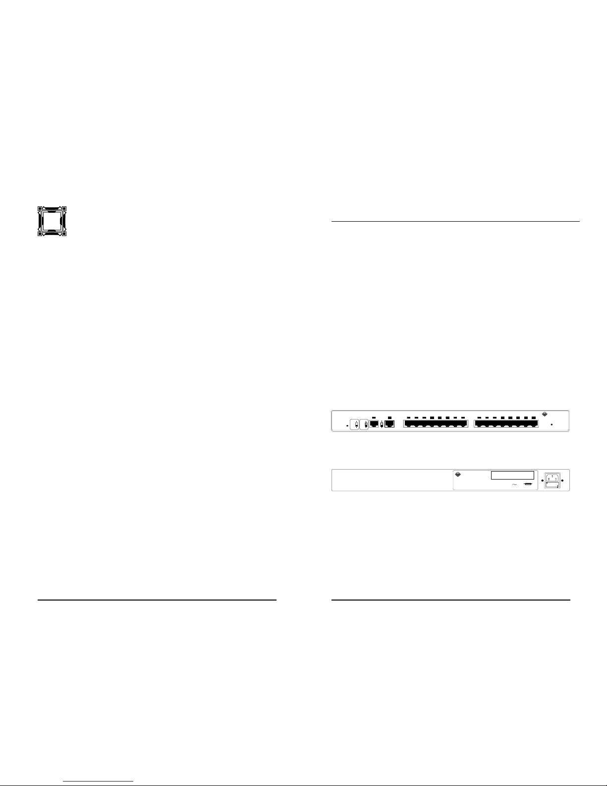
Front and back views of the LAN Master TR16 unit are illustrated
below.
Figure 2.1 Front View of the LAN Master TR16 Unit
Figure 2.2 Back View of the LAN Master TR16 Unit
110-120
220-240
Caution : For continued protection
against risk of fire, replace only with same
type and rating of fuse : 250V 2A.
Caution : Disconnect power before replacing fuse.
ATTENTION: Couper le courant avant de replacer
le fusible.
2A, 250V
Input Power: 100-240 V
50/60 Hz
0.5 A
Model#: TR-TP-HB-1600
E N G I N E E R I N G , I N C .
TRANSITION
7090 Shady Oak Road
Mpls, MN 55344
12345678 910111213141516
Lobe Ports
16 Port Active Media Hub
Insert Normal
Power
R OR I
4
Passive
Active
Ring
Out
16
Passive
Active
Ring
In
Reset
TRANSITION
E N G I N E E R I N G , I N C .
™
LAN Master TR16
Warranty Statement
A. Five Year Warranty
Transition Networks, Inc. (TN) warrants, for a period of five years, that TN
products (with the exception of power supplies and fans that TN warrants for
two years) will be free from defects in materials and workmanship, and will be in
conformity with TN’s specifications.
TN’s warranty on products manufactured by or assembled for TN in accordance with a
customer’s specifications, is a five-year warranty that the goods conform to such
specifications.
The warranty is invalidated if the goods have been subject to alterations, misuse, accident,
Acts of God (e.g., damage by floods, lightning strikes, Etc.), tampering, improper
maintenance, improper installation, or abuse. If the user is unsure about the proper means
of installing or using the equipment, contact TN’s free Technical Support or Network
Design Services, which can be reached by:
Telephone 1.800.LAN.WANS or 612.941.7600
Fax 612.941.2322
E-mail [email protected]
Internet http://www.transition.com
THE ABOVE WARRANTY IS EXCLUSIVE AND EXTENDS ONLY TO PRODUCTS
ASSEMBLED BY TRANSITION NETWORKS, INC. TO THE EXTENT PERMITTED BY LAW,
TN DOES NOT MAKE AND DISCLAIMS ALL OTHER WARRANTIES, EXCEPT TITLE,
EXPRESSED OR IMPLIED, INCLUDING, BUT NOT LIMITED TO, ANY WARRANTY OF
DESCRIPTION, MERCHANTIBILITY, FITNESS FOR A PARTICULAR PURPOSE OR NONINFRINGEMENT, AND ANY WARRANTY BASED UPON PRIOR WRITTEN OR ORAL
REPRESENTATIONS REGARDING SUCH PRODUCTS MADE BY TN, ITS EMPLOYEES,
AGENTS, OR REPRESENTATIVES.
B. Limitations and Exclusions
If the customer believes any goods sold by TN are defective and within the warranty
period, the following general procedure will be followed:
1. Locate the serial number and delivery date of the item(s).
2. Notify TN within the warranty period.
3. TN will promptly issue a return authorization form for the goods.
4. Upon receiving the form, the customer will promptly return the item(s) at customers
own expense, shipped prepaid, to the distributor from which it was purchased, or
directly to TN.
TN will only accept goods for return if the following conditions have been met:
1. A return form is obtained from TN.
2. The freight charges have been prepaid by the customer.
3. Goods are re-packed in their original packaging.
If under warranty TN shall, at its option, (1) repair the goods free of charge (2) replace the
goods free of charge, or (3) accept the return of the item(s) and credit the current price to
the reseller (within 90 days of purchase), or (4) if the goods are not under warranty, will
repair the item(s) at a minimum charge of USD $200 (two hundred U.S. dollars) per item.
THIS IS THE EXCLUSIVE REMEDY FOR ANY BREACH OF WARRANTY. IN NO EVENT
SHALL TRANSITION NETWORKS BE LIABLE FOR SPECIAL, INDIRECT, INCIDENTAL OR
CONSEQUENTIAL DAMAGES OF ANY KIND, WHETHER FOR BREACH OF ANY
CONDITION OF SALE, FOR NEGLIGENCE, ON THE BASIS OF STRICT LIABILITY,
CONTRACT, OR OTHERWISE AND IRRESPECTIVE OF WHETHER TN IS INFORMED BY
A
Page 6

C. Function of LED’s
INSERT/BYPASS LED
Each LAN Master TR16 port has an associated Insert/Bypass LED.
The LED should remain lit if a good twisted pair cable is attached into
a LAN Master TR16 port and the station power is on.
If the LED is not lit, and a station is attached to the port, consider the
following:
• Twisted pair cable pin out wrong
• Twisted pair cable short or open
• NIC card configured improperly.
If no station is attached to the Lobe port, the LED should remain off.
RO NORMAL LED
If connected to another active hub’s RI port:
ON Indicates RO port is functioning properly and cable is good
OFF Indicates fault in RO port, in other hub’s RI port, or in cable.
If no connection to the RO port:
If no station is attached to the RO port, the LED should remain OFF.
If connected to another passive hub’s RI port (Ex: IBM8228) and the
RO switch is in the passive position:
The LED should remain ON if the LAN Master TR16 RO port is
connected to a passive hub’s RI port.
NOTE: When the RO switch is in the passive position, the indicator is
always ON.
RI INSERT LED
If connected to another active hub’s RI port:
ON Indicates RO port is functioning properly and cable is good
OFF Indicates fault in RO port, in other hub’s RI port, or in cable.
If no connection to the RO port:
If no station is attached to the RO port, the LED should remain OFF.
A-1LAN Master TR162-3 LAN Master TR16
Page 7

E. Replacing the Fuse
If the unit fails to power on, the unit fuse may be open or blown.
Disconnect the power cord from the AC wall socket, then from the
unit.
Warning: Disconnect power before replacing fuse. For continued
protection against risk of fire, replace only with same
type (European) and rating (250V 2A) of fuse.
Install the fuse holder with the proper voltage rating orientation – such
that the rating can be read (lower right corner of fuse holder).
Insert the fuse holder with 100-120 input voltage rating:
Insert the fuse holder with 220-240 input voltage rating:
If the fuse is bad, replace the fuse, close the receptacle, connect the
power cord. If the fuse is good, but the concentrator fails to power
ON, try another power cord and verify that the wall receptacle is
active.
If the unit continues to fail, refer to Section A under “C. Return
Procedure”, contact TRANSITION Networks Technical Support at
(800) 260-1312 or contact your local distributor for the proper
replacement procedure.
Warning: Do NOT, under any circumstances, open and attempt to
repair the LAN Master TR16 unit or power supply. This will
immediately void the warranty.
110-120
220-240
110-120
220-240
If connected to another passive hub’s RI port (Ex: IBM8228) and the
RO switch is in the passive position:
The LED should remain ON if the LAN Master TR16 RO port is
connected to a passive hub’s RI port.
NOTE: When RO switch is in passive position, indicator is always ON.
Power LED
A lit LED indicates that the power is on. Note: The LED will go off
momentarily when the reset switch is pressed.
D. Switches
Reset Switch Push-button switch to reset LAN Master TR16.
Ring In (RI) Switch Passive position if TP cable is attached from
the RI on the LAN Master TR16 to the RO on
a passive concentrator.
Active position if TP cable is attached from
the RI on the LAN Master TR16 to the RO on
an active concentrator.
If there is no connection to the RI port, the
RI switch should be in Active position.
Ring Out (RO) Switch Passive position if TP cable is attached from
the RO on the LAN Master TR16 to the RI on
a passive concentrator.
Active position if TP cable is attached from
the RO on the LAN Master TR16 to the RI on
an active concentrator.
If there is no connection to the RO port, the
RO switch should be in Active position.
16/4 Switch Select the data rate (4Mbps or 16Mbps), then
press the reset button.
ZDL Switch Enable automatic speed detection. Default is
ON position. Use OFF only when connecting
non-802.5 compliant test equipment (such as
Hewlet Packard token ring tester).
Installing The Hardware
LAN Master TR163-3 2-4LAN Master TR16
Page 8
C. Attaching the LAN Master TR16 to Rackmount Frame
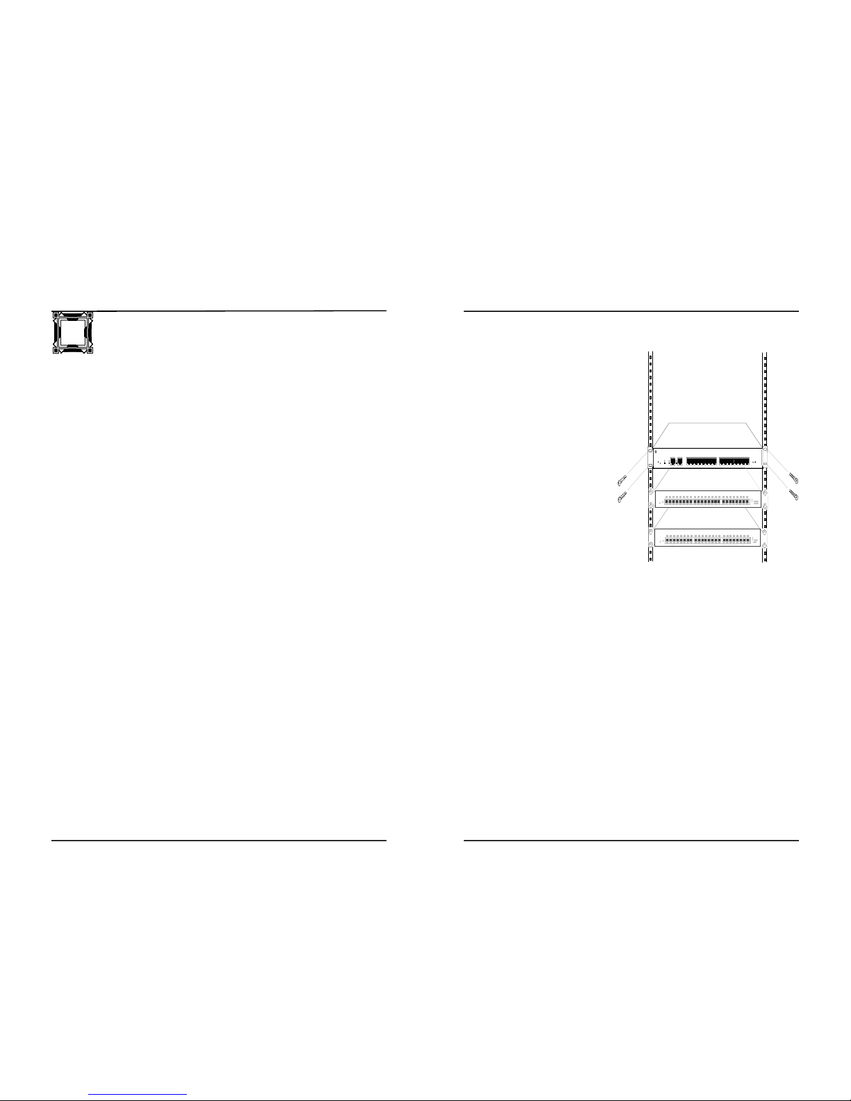
The LAN Master TR16 unit is shipped with a set of mounting brackets
attached. The unit can be
mounted in a standard EIA 19”
rackmount. If not needed, the
mounting brackets can be
removed and saved for future
use.
Mount the LAN Master TR16
unit into the rackmount frame.
Rackmount screws are not
provided with the unit. Attach
and tighten the rackmount
screws into the mounting
brackets and threaded holes of
the rackmount.
D. Attaching the Twisted Pair
Cable
The twisted pair cable can be
attached from the LAN Master TR16 to any DTE device. The
maximum cable lengths are summarized in section C, under “Cable
Type”.
Each of the lobe or RJ-45 ports have an associated LED. The LED is
bright when the twisted pair cable connected into the lobe port and
establishes a connection to the remote Token Ring card. If the LED
fails to appear bright, consider the following:
1. The twisted pair connectors on either end are not properly attached
to the ports.
2. The twisted pair cable is shorted or open wire.
3. Software or jumper connection on the concentrator or remote card
is not properly set for passive/active or the network configuration of
4 or 16 Mbps.
4. The concentrator or remote Token Ring workstation is locked-up.
Press the reset switch on the LAN Master TR16 unit and/or reboot
the workstation.
5. The DTE device is not powered on.
INSTALLING THE HARDWARE
A. Installation Considerations
• The AC power outlet (85 to 265 VAC at 47 to 63 Hz) for the
LAN Master TR16 unit is referenced in Appendix D, Technical
Specifications.
• Suitable rack space to mount the MAU for proper ventilation.
• Refer to appendix D for environmental considerations.
• The twisted pair cable should not be located close to any sources of
electrical noise (such as radio transmitters and broadband amplifiers,
motors, high power electrical lines, or fluorescent light fixtures).
• The TP cable does not run in the same conduit with power lines.
• Phone lines should be separated from data cables.
• Do not use flat or "silver satin" wire.
B. Pin Assignments for the Twisted Pair Cable Connector
If the Token Ring adapter card has an RJ-45 port, a straight through
connection between the LAN Master TR16 and adapter card is needed.
3 to 3
4 to 4
5 to 5
6 to 6
Pins 3 and 6 are twisted pair
Pins 4 and 5 are twisted pair
Installing The Hardware
LAN Master TR163-1 3-2LAN Master TR16
3
StackMaster™ 24 Port Manageable 10BaseT Hub
StackMaster™ 24 Port Manageable 10BaseT Hub
 Loading...