

MiLAN MIL-W0311, MIL-W1311 User Manual
ShAir Office
Multi-Function
Internet & Wireless Gateway
Models MIL-W0311 & MIL-W1311
Broadband Internet Access
Wireless Access Point
Dial-in RAS
Print Server
User’s Guide

i
T
ABLE OF CONTENTS
CHAPTER 1 INTRODUCTION.............................................................................................. 1
Wireless Gateway Features .............................................................................................. 1
Package Contents ..............................................................................................................4
Physical Details.................................................................................................................. 4
CHAPTER 2 INSTALLATION............................................................................................... 8
Requirements ..................................................................................................................... 8
Procedure ........................................................................................................................... 8
CHAPTER 3 CONFIGURATION......................................................................................... 10
Overview .......................................................................................................................... 10
Configuration Program................................................................................................... 11
Quick Setup Screen .........................................................................................................13
Wireless Screen................................................................................................................ 17
Status Screen.................................................................................................................... 20
CHAPTER 4 PC CONFIGURATION...................................................................................26
Overview .......................................................................................................................... 26
Windows Clients .............................................................................................................. 26
Macintosh Clients ............................................................................................................ 37
Linux Clients.................................................................................................................... 38
Other Unix Systems......................................................................................................... 39
Wireless Station Configuration ...................................................................................... 39
CHAPTER 5 DHCP ................................................................................................................ 40
Overview .......................................................................................................................... 40
What DHCP Does............................................................................................................ 40
Using the Wireless Gateway's DHCP Server ................................................................ 40
Using another DHCP Server ..........................................................................................40
To Configure your PCs to use DHCP ............................................................................ 41
CHAPTER 6 SERIAL PORT................................................................................................. 42
Overview .......................................................................................................................... 42
Serial Port Screen............................................................................................................ 42
Modem Properties Screen............................................................................................... 45
Dial -in Users.................................................................................................................... 47
Serial Port Status............................................................................................................. 51
CHAPTER 7 OPTIONS .........................................................................................................54
Overview .......................................................................................................................... 54
Password .......................................................................................................................... 54
DNS (Domain Name Server............................................................................................ 55
NAT (Network Address Translation) ............................................................................ 55
TFTP................................................................................................................................. 55
Remote Management....................................................................................................... 55
Routing Table .................................................................................................................. 56
Printer Port...................................................................................................................... 56
CHAPTER 8 ROUTING ........................................................................................................ 58
Overview .......................................................................................................................... 58
Routing Screen................................................................................................................. 58
Router Configuration...................................................................................................... 60
Static Routing - Example ............................................................................................... 61
CHAPTER 9 ADVANCED INTERNET............................................................................... 62
Overview
......................................................................................................................... 62
Advanced Internet Screen............................................................................................... 62
Special Internet Applications ......................................................................................... 63

ii
URL Filter........................................................................................................................ 66
Virtual Servers.................................................................................................................68
DMZ.................................................................................................................................. 73
CHAPTER 10 ACCESS CONTROL..................................................................................... 75
Overview .......................................................................................................................... 75
Security Groups Screen................................................................................................... 76
PCs Screen........................................................................................................................ 78
Filters Screen ...................................................................................................................80
APPENDIX A TROUBLESHOOTING ................................................................................ 81
Overview .......................................................................................................................... 81
General Problems ............................................................................................................ 81
Internet Access.................................................................................................................81
Wireless Access ................................................................................................................ 82
Printing............................................................................................................................. 83
Dial-in Access................................................................................................................... 86
APPENDIX B ABOUT WIRELESS LANS .......................................................................... 88
Modes ............................................................................................................................... 88
BSS/ESS............................................................................................................................ 88
Channels........................................................................................................................... 89
WEP.................................................................................................................................. 89
Access Control ................................................................................................................. 90
Wireless LAN Configuration.......................................................................................... 90
APPENDIX C AT COMMANDS........................................................................................... 91
AT Commands .................................................................................................................91
Standard AT Commands ................................................................................................ 93
APPENDIX D SPECIFICATIONS........................................................................................ 96
Wireless Gateway ............................................................................................................ 96
PCMCIA Wireless Card (MIL-W1311 only)
.............................................................. 97
P/N: 9560DP0101
Copyright 2001. All Rights Reserved.
Document Version: 1.0
All trademarks and trade names are the properties of their respective owners.
1
Chapter 1
Introduction
This Chapter provides an overview of the Wireless Gateway's features and
capabilities.
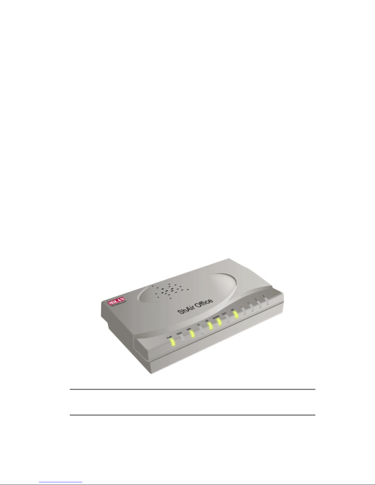
Congratulations on the purchase of your new Wireless Gateway Multi-Function Wireless
Gateway. The Wireless Gateway is a multi-function device providing the following services
(the wireless functions are only available on the MIL-W1311 or an MIL-W0133 with an MILW1897 wireless adapter):
•
Shared Internet Access
via an DSL or Cable modem on the WAN (Ethernet) port, OR via
an analog modem or ISDN TA on the Serial (RS232) port.
•
Wireless LAN Access Point
(base station) for equipment compliant with the IEEE802.11b
(DSSS) specifications. Available on the MIL-W1311 (MIL-W0311 with MIL-W1897)
•
Network Printer
- LAN and WLAN users can share the printer attached to the Wireless
Gateway.
•
RAS Dial-in Access
- Remote users can use the Wireless Gateway to connect to the LAN
and access LAN resources, including the Wireless Gateway's printer and Broadband Internet access.
Figure 1:
Wireless Gateway
Wireless Gateway Features
The Wireless Gateway incorporates many advanced features, carefully designed to provide
sophisticated functions while being easy to use.
LAN Features
•
Dual LAN ports.
The Wireless Gateway has two (2) 10/100BaseT Ethernet LAN ports.
Normally, the “Hub” port is used to connect the Wireless Gateway to a 10/100BaseT hub
on your LAN. But if desired, the “PC” port can be used to connect the Wireless Gateway
directly to your PC, using a standard LAN cable.
•
DHCP Server Support.
D
ynamic Host Configuration Protocol provides a dynamic IP
address to PCs and other devices upon request. The Wireless Gateway can act as a
DHCP
Server
for devices on your local LAN and WLAN.
1

Wireless Gateway User Guide
2
•
Multi Segment LAN Support. LANs containing one or more segments are supported,
via the Wireless Gateway's built-in static routing table. If NAT (Network Address Translation) is disabled, the Wireless Gateway will function as a static router.
Internet Access Features
•
Shared Internet Access. All users on the LAN or WLAN can access the Internet
through the Wireless Gateway, using only a single external IP Address. The local (invalid)
IP Addresses are hidden from external sources. This process is called NAT (Network Address Translation).
•
DSL & Cable Modem Support. The Wireless Gateway has a 10BaseT Ethernet port
for connecting an DSL or Cable Modem. All popular DSL and Cable Modems are supported.
•
Analog Modem and ISDN TA Support. If you don't yet have Broadband Internet
access, the Wireless Gateway can provide shared Internet access via an analog modem or
ISDN TA connected to the serial (RS232) port.
•
PPPoE Support.
The WAN port connection can use PPPoE (PPP over Ethernet), if your
ISP uses this method.
•
Fixed or Dynamic IP Address.
On the WAN connection, the Wireless Gateway
supports both Dynamic IP Address (IP Address is allocated on connection) and Fixed IP
Address.
Wireless Features
•
Standards Compliant. The Wireless Gateway complies with the IEEE802.11b (DSSS)
specifications for Wireless LANs.
•
Security Features. Support for WEP (Wired Equivalent Privacy) and Access Control is
included.
•
Simple Configuration.
If the default settings are unsuitable, they can be changed
quickly and easily.
Network Printer
•
Share your Printer. A printer connected to the Wireless Gateway's parallel port can be
used by all PCs on the LAN.
•
Multiple Operating Systems.
Clients may use any of the following operating systems:
•
Windows 95/98/ME
•
Windows NT 4.0 or 2000
•
Apple Macintosh
•
Unix
•
Multi--protocol Support.
The following printing methods are supported:
•
Windows peer-to-peer printing over TCP/IP, using the supplied port driver.
•
Windows LPD printing, using a Windows Server running NT 4.0 or Windows 2000
Server. In this situation, no software needs to be installed on the client PCs.
•
Unix LPD printing. No additional software needs to be installed.

Introduction
3
Advanced Internet Functions
•
Virtual Servers.
This feature allows Internet users to access Internet servers on your
LAN. The required setup is quick and easy.
•
User-Defined Virtual Servers. Internet users can access non-standard Internet Servers
on your LAN by using this feature.
•
Special Internet Applications. Internet applications such as Internet Videoconferenc-
ing, Telephony, Games Servers, and other special-purpose Servers are supported.
•
DMZ. One (1) PC on your local LAN can be configured to allow unrestricted 2-way
communication with Servers or individual users on the Internet.
•
URL Filter.
Use
the URL Filter to block access to undesirable Web sites by LAN users,
Wireless LAN users, or the Dial-in user.
•
Internet Access Log. See which Internet connections have been made.
RAS (Remote Access Services)
•
RAS Dial-in. Remote PC users can use their standard Dial-up software to connect to the
Wireless Gateway and access LAN resources.
•
Dial-back Support. For additional security, the Dial-back feature can be used to hang up
and re-dial the remote user. Both fixed and roaming options are supported.
Configuration & Management
•
Easy Setup. Use your WEB browser from anywhere on the LAN for configuration.
•
Remote Management. The Wireless Gateway can be managed from any PC on your
LAN. And, if the Internet connection exists, it can also (optionally) be configured via the
Internet.
Security Features
•
Configuration Data. Optional password protection is provided to prevent unauthorized
users from modifying the configuration.
•
Access Control Features
. The LAN Administrator can limit Internet access by individual workstations. And the Access Control log allows the Administrator to see attempted
accesses which have been blocked.
•
Wireless LAN Security
. WEP (Wired Equivalent Privacy) is supported, as well as
Wireless access control via station address.
•
Firewall Protection.
All incoming data packets are monitored and all incoming server
requests are filtered, thus protecting your network from malicious attacks from external
sources. (This protection is lost if NAT is disabled.)

Wireless Gateway User Guide
4
NAT Firewall Protection
The firewall protection provided by the Wireless Gateway is an intrinsic side effect
of NAT (Network Address Translation). All users on the LAN share a single
external IP address. From the external viewpoint, there is no network, only a single
device.
For internal users, the Wireless Gateway acts as a “transparent proxy server”,
translating the multiple internal IP addresses into a single external IP address.
For external requests, any attempt to connect to local resources is blocked. The
Wireless Gateway will not “reverse translate” from a external IP address to a local
IP address.
This type of “natural” firewall provides an impregnable barrier against malicious
attacks.
Package Contents
The following items should be included:
•
The Wireless Gateway Unit
•
Wireless PCMCIA Card
•
Power Adapter
•
Quick Installation Guide
•
CD-ROM containing the on-line manual and Print Port Driver.
If any of the above items are damaged or missing, please contact your dealer immediately.
Physical Details
Top-mounted LEDs
Power On
- Power on.
Off
- No power.
Status (Red) On
- Error condition.
Off
- Normal operation.
Blinking
- This LED blinks during start up.
WAN On
- WAN connection is established.
Flashing
- Data is being transmitted or received via the WAN port.
LAN: 10 On
- LAN connection is using 10BaseT.
Off
- No LAN connection.
Flashing
- Data is being transmitted or received via the LAN port.
LAN: 100 On
- LAN connection is using 100BaseT.
Off
- No LAN connection.
Flashing
- Data is being transmitted or received via the LAN port.
Introduction
5
Wireless On
- Wireless connection available; Wireless Access Point is ready for
use.
Off
- No Wireless connection available.
Flashing
- Data is transmitted or received via the Wireless access point.
This includes "network traffic" as well as user data.
Print Error On
- Printer error detected.
Off
- No printer error detected.
Print Act On
- Connection to printer established.
Off
- No connection to printer; printer is Off or Off-line.
Flashing
- Data is being transmitted to the printer.
COM
(Serial Port)
Off
- Idle or no active device connected to the serial (RS232) port.
Flashing
- Data is transmitted or received via the serial (RS232) port.
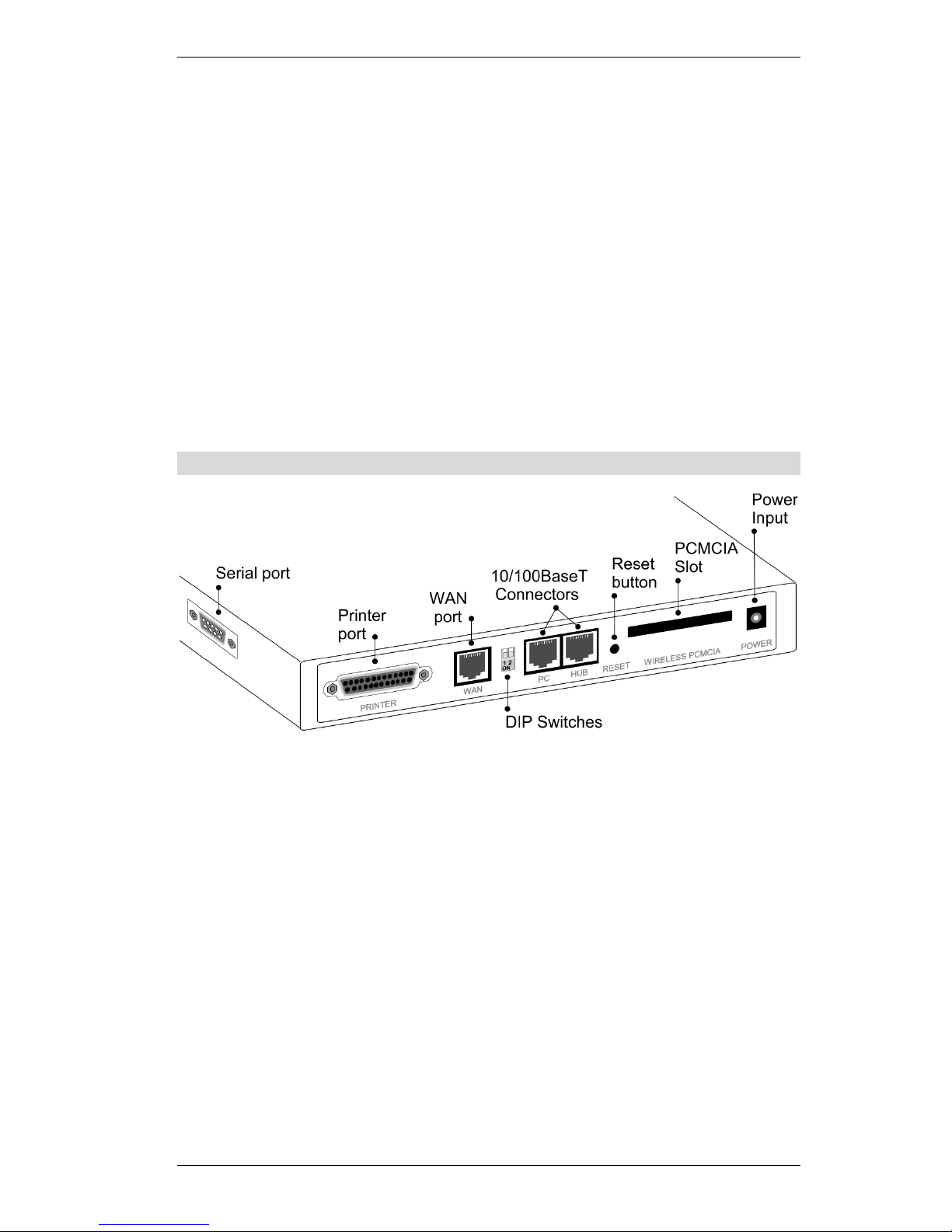
Rear Panel
Figure 2: Rear Panel
Serial Port
RS232 Serial Port. If you have an analog modem or ISDN TA,
connect it here.
Printer Port
Standard parallel printer port. If you wish to share a printer, connect it
here.
WAN port
(10BaseT)
Connect the DSL or Cable Modem here. If your modem came with a
cable, use the supplied cable. Otherwise, use a standard LAN cable.
DIP switches
Refer to the following table.
PC port
(10/100BaseT)
If connecting directly to your PC (no Hub) use this port and a standard LAN cable (RJ45 connectors).
Use EITHER the PC port OR the Hub port, NOT both.
HUB port
(10/100BaseT)
Use a standard LAN cable (RJ45 connectors) to connect this port to a
10BaseT or 100BaseT hub.
Use EITHER the PC port OR the Hub port, NOT both.

Wireless Gateway User Guide
6
Reset Button
This button has three (3) functions:
•
Reboot
. When pressed and released, the Wireless Gateway will
reboot (restart).
•
Diagnostic print-out
. If held down for 3 seconds, a diagnostic
print-out will be sent to the attached printer.
•
Ensure the printer is ready.
•
Both Print LEDs will flash simultaneously during the diagnostic printing.
•
Clear All Data
. This button can also be used to clear ALL data
and restore ALL settings to the factory default values.
To Clear All Data and restore the factory default values:
1. Power Off.
2. Hold the Reset Button down while you Power On.
3. Keep holding the Reset Button for a few seconds, until the RED
LED has flashed TWICE.
4. Release the Reset Button. The Wireless Gateway is now using
the factory default values.
PCMCIA slot
Insert the supplied Wireless PCMCIA card into this slot.
•
Ensure the power is OFF before inserting or removing the
PCMCIA Card.
•
Do not use any other PCMCIA Card.
Power port (12V)
Connect the supplied power adapter here.
Introduction
7
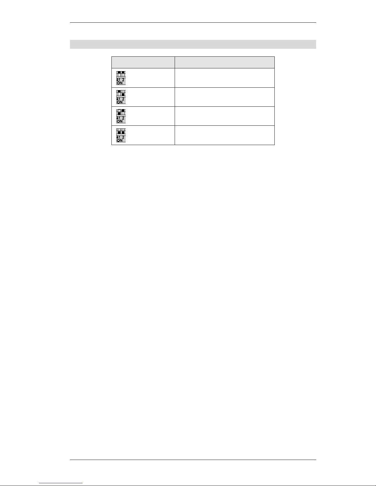
DIP Switches
DIP Switch Setting Description
1=off
2=off
Normal Operation.
1=off
2=on
DHCP Server function disabled.
1=on
2=off
Used to restore Default IP Address
and clear Password (See below).
1=on
2=on
Normal Operation.
Restore Default IP Address and Clear Password
If the Wireless Gateway's IP Address or password is lost, the following procedure can be used
to recover from this situation.
1. Turn the power to the Wireless Gateway OFF.
2. Set DIP switch 1 ON.
3. Turn the power to the Wireless Gateway ON.
4. Operate DIP switch 1 in the following sequence (you have 15 seconds to complete the
sequence):
•
OFF
•
ON
•
OFF
5. The Wireless Gateway will now reset, and the Red Status LED flash. The following
changes will have been made. (Other configuration data is unchanged.)
•
IP Address set to its default value of 192.168.0.1
•
Network Mask set to 255.255.255.0
•
DHCP Server is enabled, and will allocate IP Addresses in the range 192.168.0.2 to
192.168.0.51.
•
The password cleared (no password).
6. You can now connect to the Wireless Gateway and make any configuration changes
required.
8
Chapter 2
Installation
This Chapter covers the physical installation of the Wireless Gateway.
Requirements
•
Ethernet LAN (10/100BaseT) and the TCP/IP protocol.
•
For Internet Access, an Internet Access account with an ISP, and either of:
•
A DSL or Cable modem (for WAN port usage)
•
An analog modem or ISDN TA (for serial port usage)
•
To use the Wireless Access Point, all Wireless devices must be compliant with the
IEEE802.11b specifications.
•
For shared access to the attached printer, the following clients are supported:
•
Windows 95/98/ME
•
Windows NT 4.0 or 2000
•
Apple Macintosh
•
Unix (LPD printing)
Procedure
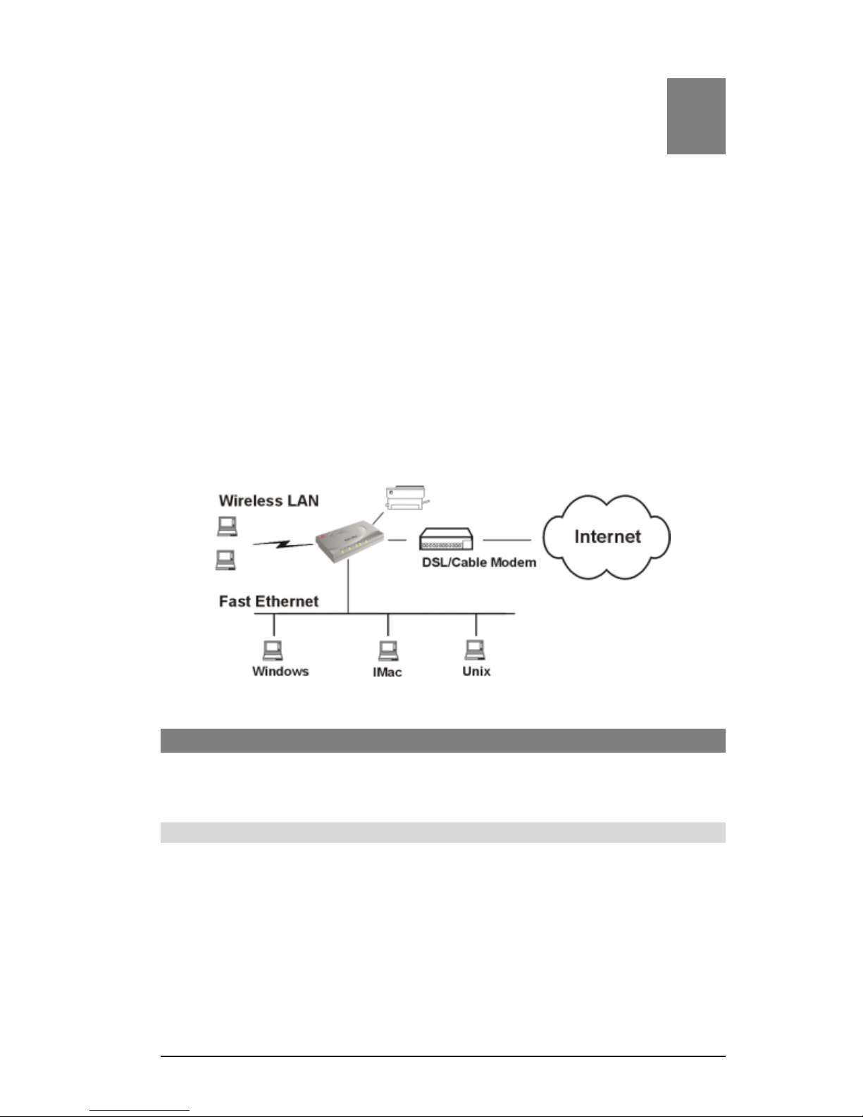
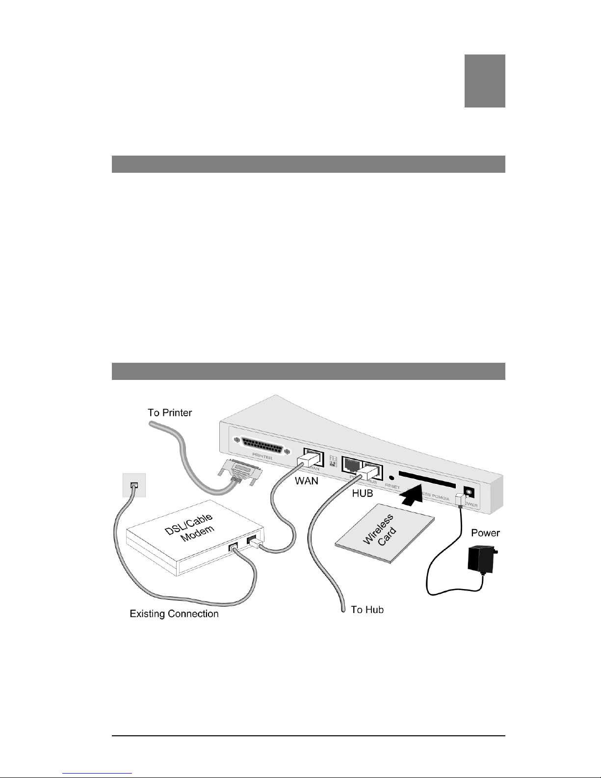
Figure 3: Installation Diagram
1. Choose an Installation Site
Select a suitable physical location. Ensure the Wireless Gateway and the DSL/Cable modem are powered OFF.
2

Installation
9
2. Insert Wireless PCMCIA card
Ensuring the supplied Wireless PCMCIA card is the right way up, insert it into the slot on
the rear. Push it firmly until it clicks into position.
3. Connect LAN Cable
Connect a standard LAN cable from a 10BaseT or 100BaseT Hub on your LAN to the
“HUB” port on the Wireless Gateway.
4. Connect WAN Cable
If you have a DSL modem or Cable modem, connect it to the WAN port on the Wireless
Gateway. Use the cable supplied with your modem. If no cable was supplied, use a standard LAN cable.
5. Connect Modem (optional)
If you wish to use an Analog modem or ISDN TA, use a standard serial cable to connect it
to the Serial port on the Wireless Gateway.
6. Connect Printer Cable
Use a standard parallel printer cable to connect your printer to the Printer port on the
Wireless Gateway.
7. Power Up
Connect the supplied power adapter and power up.
Use only the power adapter provided.
8. Check the LEDs
•
The Status LED should flash, then turn Off. If it stays on, there is a hardware error.
•
The Power LED should be ON.
•
One (1) of the LAN LEDs (10 or 100) should be ON.
•
The Wireless LED should be ON.
•
If the printer is On and On-line, the Print Act LED should be ON.
For more information, refer to Top-mounted LEDs in Chapter 1.

10
Chapter 3
Configuration
This Chapter provides details of the configuration process.
Overview
This chapter describes the procedure for:
•
Quick setup
•
Wireless access point configuration
•
Using the Status screens
PCs on your local LAN may also require configuration. For details, see Chapter 4 - PC Con-
figuration.
Other configuration may also be required, depending on which features and functions of the
Wireless Gateway you wish to use. Use the table below to locate detailed instructions for the
required functions.
To Do this: Refer to:
Configure PCs on your LAN. Chapter 4:
PC Configuration
Learn more about using DHCP on the internal LAN. Chapter 5:
DHCP
Configure and use the Serial (RS232) port, either for Internet access
or for Dial-in.
Chapter 6:
Serial Port
Configure various options:
•
Set a password for the Wireless Gateway, to protect the configuration data.
•
Disable NAT (Network Address Translation),
•
Enable TFTP firmware upgrade feature.
•
Configure Remote Management (configure via the Internet)
•
Access the Printer Port setup screen.
Chapter 7:
Options
Configure the Wireless Gateway and other routers for a LAN which
already has 1 or more routers.
Chapter 8:
Routing
Use any of the following features:
•
Special Internet Applications
•
URL Filter
•
Virtual Servers
•
DMZ
Chapter 9:
Advanced Internet
Features
Limit Internet Access by individual workstations. Chapter 10:
Access Control
3

Configuration
11
Where use of a certain feature requires that
PCs or other LAN devices be configured, this
is also explained in the relevant chapter.
Configuration Program
The Wireless Gateway contains an HTTP server. This enables you to connect to it, and configure it, using your Web Browser.
Most Browsers should work, provided they support HTML tables and forms.
Preparation
Before attempting to configure the Wireless Gateway, please ensure that:
•
Your PC can establish a physical connection to the Wireless Gateway. The PC and the
Wireless Gateway must be directly connected (using the “PC” port on the Wireless Gateway) or on the same LAN segment.
•
The Wireless Gateway must be installed and powered ON.
•
If the Wireless Gateway's default IP Address (192.168.0.1) is already used by another
device, the other device must be turned OFF until the Wireless Gateway is allocated a new
IP Address during configuration.
Connecting to the Wireless Gateway
To establish a connection from your PC to the device:
1. After installing the Wireless Gateway in your LAN, start your PC. If your PC is already
running, restart it.
2. Start your WEB browser.
3. In the Address box, enter "HTTP://" and the IP Address of the Wireless Gateway, as in this
example, which uses the Wireless Gateway’s default IP Address:
HTTP://192.168.0.1
4. You should then see the Quick Setup screen.
See the following section for details on using this screen.
If you can't connect
If the Wireless Gateway does not respond, check the following:
•
The Wireless Gateway is properly installed, LAN connection is OK, and it is
powered ON.
•
Ensure that your PC and the Wireless Gateway are on the same network segment. (If you don't have a router, this must be the case.)
•
If your PC is using a fixed IP Address, its IP Address must be within the range
192.168.0.2 to 192.168.0.254 to be compatible with the Wireless Gateway's default IP Address of 192.168.0.1. Also, the Network Mask must be set to
255.255.255.0. See Chapter 4 – PC Configuration for details on checking your
PC’s TCP/IP settings.
Wireless Gateway User Guide
12
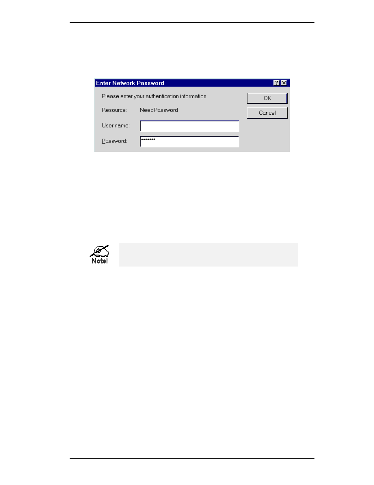
Password
If you have assigned a password to the Wireless Gateway (on the Options screen) you will be
prompted for the password, as shown below. (If no password has been set, this dialog will not
appear.)
Figure 4: Password Dialog
•
Leave the "User Name" blank.
•
Enter the password for the Wireless Gateway, as set on the Options screen.
Navigation & Data Input
•
Use the menu bar on the left of the screen, and the "Back" button on your Browser, for
navigation.
•
Changing to another screen without clicking "Save" does NOT save any changes you may
have made. You must “Save” before changing screens or your data will be ignored.
On each screen, clicking the "Help" icon will display help for that screen.
Configuration
13
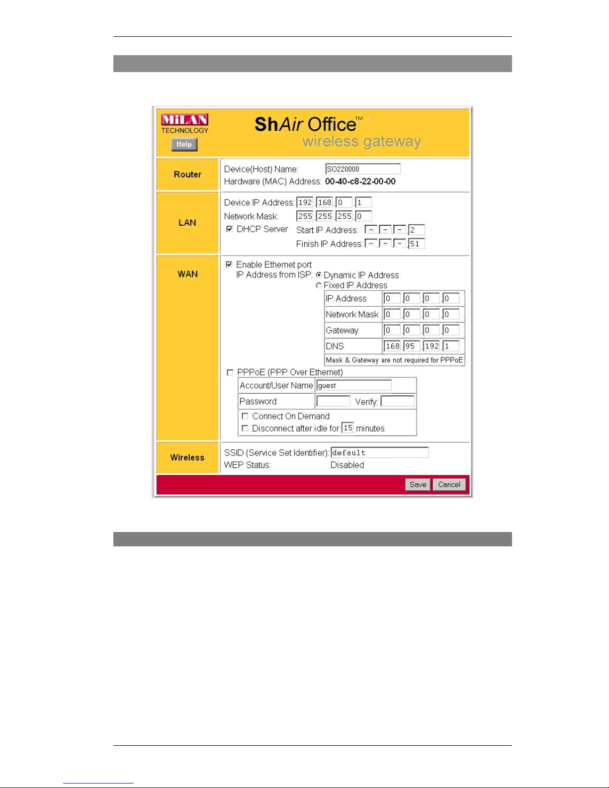
Quick Setup Screen
The Quick Setup screen, like the example below, will be displayed when you first connect.
Figure 5: Quick Setup Screen
Quick Setup - Overview
This screen contains all the basic data to make the Wireless Gateway operational.
For many users, the default values will be satisfactory, and no changes will be required.
•
Router
Most users do not need to change these values.
•
LAN Settings
There is no need to change the LAN settings unless:
•
You wish to use a different IP Address range
•
You already have a DHCP Server or a Router on your LAN.
See Chapter 5 -DHCP for more details about DHCP, or Chapter 8 - Routing for de-
tails about using Routers on your LAN.
•
WAN Port Settings
By default, the Wireless Gateway is configured for WAN access
using a "Direct Connection" (cable modem or permanent DSL link) and a dynamic IP Address (the IP Address is supplied by your ISP when you connect). For this common
situation, no changes are required.

Wireless Gateway User Guide
14
•
Wireless Access Point
To use the Wireless Access Point:
•
All Wireless devices must have the same SSID. Either the Wireless Access Point or
the Wireless clients can be changed to ensure this.
•
All Wireless devices must have the same settings for WEP (Wired Equivalent Privacy).
By default, WEP on the Wireless Gateway is
Disabled
, so clients also need to have
WEP
Disabled
.
•
See Appendix B for more details about Wireless LANs and WEP, and the Wireless
Screen section later in this chapter for details of the Wireless Gateway's Wireless
screen.
Configuration Data - Quick Setup Screen
Router
Device (Host)
Name
Normally, there is no need to change the default name, but if your ISP
requests that you use a particular “Hostname”, enter it here. This name
will be provided to, and recorded by, the remote DHCP Server.
Hardware
(MAC)
Address
Also called Network Adapter Address or Physical Address. This is a low-
level identifier for the Wireless Gateway, as seen from the WAN port.
Provide this value to your ISP if requested. If you did not provide this
value when first connected, there is no need to provide it now.
LAN
Device
IP Address
IP address for the Wireless Gateway, as seen from the local LAN. Use
the default value of 192.168.0.1 unless the address is already in use or
your LAN is using a different IP address range. In the latter case, enter an
unused IP Address from within the range used by your LAN.
Network Mask
The default value 255.255.255.0 is standard for small (class "C") networks. For other networks, use the Network Mask for the LAN segment
to which the Wireless Gateway is attached. i.e. the same value as the PCs
on that LAN segment.
DHCP Server
See Chapter 5 for further details about DHCP.
•
If
Enabled
, the Wireless Gateway will allocate IP Addresses to PCs
on your LAN. The default and recommended value is
Enabled
.
•
If you are already using a DHCP Server, this setting must be
DISABLED, and the existing DHCP server must be re-configured as
described in Chapter 5 - DHCP.
•
The
Start IP Address
and
Finish IP Address fields
set the values
used by the DHCP server when allocating IP Addresses to DHCP
clients.
This range also determines the number of DHCP clients supported.
(Maximum 253.)

Configuration
15
WAN
Enable
Ethernet Port
Normally, this should be left at the default value of
Enabled
.
•
If no DSL or Cable modem is connected to the WAN (Ethernet)
port, then this setting should be Disabled.
•
If Internet access via the Serial Port is Enabled, this setting will be
automatically Disabled. It is not possible to simultaneously use both
the WAN (Ethernet) port and the Serial (RS232) port for Internet access.
IP Address
from ISP
Dynamic IP Address
. This is the default, and the most common.
Leave this selected if your ISP allocates an IP Address to the Wireless
Gateway upon connection.
Fixed IP Address
. Select this if your ISP has allocated you a fixed IP
Address. If this option is selected, the following data must be entered.
•
IP Address
.
The IP Address allocated by the ISP.
•
Network Mask (Not required for PPPoE)
This is also supplied by your ISP. It must be compatible with the IP
Address above.
•
Gateway IP Address (Not required for PPPoE)
The address of the Gateway or gateway, as supplied by your ISP.
•
DNS IP Address
The DNS (Domain Name Server) IP Address provided by your ISP.
If required, additional DNS entries can be made on the Options
screen.
PPPoE
If your ISP uses PPPoE, enable this checkbox and enter the data in the
PPPoE section, as described below.
If your ISP's data does not mention "PPPoE", do NOT enable this option.
Account/User
Name
The "Login" name, or the name of the Internet account provided by your
ISP.
Password
and Verify
Enter the password for the above account.
Re-enter the password in the Verify field, to ensure it is correct.
Connect
on Demand
Normally, this should be Enabled.
If disabled, you must use the Connect button on the
Status
screen to
establish a connection.
Disconnect
after Idle
Enable this if you wish an idle connection to be terminated.
If enabled, enter the idle time-out period (in minutes) in the field provided. After the connection to your ISP has been idle for this time period,
the connection will be terminated.
Wireless
SSID
(Service Set
Identifier)
To communicate, all Wireless stations MUST use the same SSID/ESSID.
You can either change this value, or change your client Wireless stations,
to ensure this.
The default SSID value for the Wireless Gateway is default.
Note! The SSID is case sensitive.

Wireless Gateway User Guide
16
WEP Status
This will state "Enabled" or "Disabled".
The default is "Disabled".
•
In order to use the Wireless Gateway's access point, the client
wireless stations must have the same settings for WEP.
•
To change the Wireless Gateway's WEP settings, use the
Wireless
screen, described in the following section.
Buttons
Save
Save any data you have entered on this screen. Remember to save before
changing to another screen.
Cancel
Cancel any changes you have made since the last "Save" operation.
Once this screen is completed, the Wireless Gateway is ready for use.
•
If you wish to use WEP, or change other Wireless Access Point settings, refer to the
following section.
•
Your PCs may require configuration. Refer to Chapter 4 - PC Configuration for details.
•
To check the status of the Wireless Gateway, and confirm that it is working correctly, refer
to the Status Screen section later in this Chapter.
Configuration
17
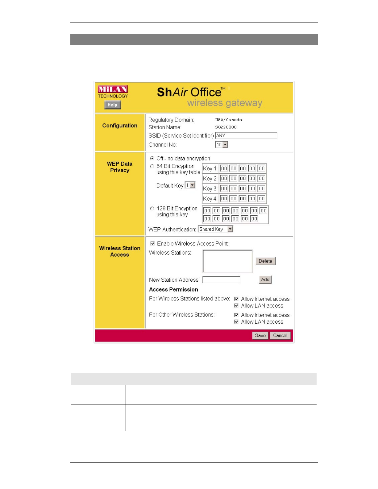
Wireless Screen
The Wireless Access Point settings must match the other Wireless stations. To change the
Wireless Gateway's default settings for the Wireless Access Point, use the Wireless link on the
main menu to reach the
Wireless
screen. An example screen is shown below.
Figure 6: Wireless Screen
Data – Wireless Screen
Configuration
Regulatory
Domain
It is illegal to use this device in any location outside of the regulatory
domain.
Station name
This is the same as the Device (Host) Name on the WAN screen. On
your PC, some Wireless status screens may display this name as the
Access Point in use.

Wireless Gateway User Guide
18
SSID
(ESSID)
To communicate, all Wireless stations MUST use the same
SSID/ESSID.
The default value is default
Note! The SSID is case sensitive.
Channel No.
Select the value you wish to use on your Wireless LAN. If you experience lost connections and/or slow data transfers you may need to
experiment with different channels to see which is the best.
WEP Data Privacy
Off
If OFF (default), data is NOT encrypted before being transmitted.
64 Bit
Encryption
•
If selected, data is encrypted, using the default key, before being
transmitted. The receiving station must be set to 64 Bit Encryption,
and have the same Key value in the same position in its key table.
Otherwise, it will not be able to decrypt the data.
•
Default Key
Select the key you wish to be the default. Transmitted data is
ALWAYS encrypted using the Default Key; the other Keys are for
decryption only.
•
Key Table
•
This table is used when Encrypting and Decrypting data. All
stations, including this Access Point, always transmit data encrypted using their default key. The key number (1, 2, 3, 4) is
also transmitted. The receiving station will use the key number
(1, 2, 3, 4) to determine which key value to use for decryption.
If the key value does not match the transmitting station, decryption will fail.
•
The easiest way to ensure there are no problems is to have
every Station, including the Access Point, use the same key table (all entries identical). Then, it does not matter which key is
used as the default key.
128 Bit
Encryption
•
If selected, data is encrypted using the key before being transmitted. The receiving station must be set to use 128 Bit Encryption,
and have the same Key value. Otherwise, it will not be able to decrypt the data.
•
Key
Enter the key value you wish to use. Other stations must have the
same key.
WEP
Authentication
Select the appropriate value - "Open System" or "Shared Key". Check
your Wireless card's documentation to see what method to use. Some
Wireless cards do not support both methods.
Wireless Station Access
Enable Wireless
Access Point
•
If enabled (default), this device can act as a Wireless Access Point.
•
If not enabled, no Wireless stations can use this device as a Wireless Access Point.

Configuration
19
Existing Stations
•
This lists the Wireless stations you have entered. If you have not
entered any stations, this list will be empty.
•
To delete an entry, select it, and click the "Delete" button. Multiple
entries may be selected by hold down the CTRL key while selecting. (On the Macintosh, use SHIFT instead of CTRL.)
New station
Address
•
Use this field to add a new station to the list. Just enter its address
here, and click the "Add" button.
•
Use the software supplied with your Wireless unit to determine its
address. The address consists of 12 letters (A..F) and digits (0..9)
like this example:
10F810A81091
The address may be shown with separators ( : or - ) between each
pair of characters.
Do NOT enter the separators ( : or - ) in this field.
Access
Permission
•
For Wireless Stations listed above
This setting determines what type of access is available to Wireless
stations whose address has been entered in the "Wireless Stations"
list.
•
For Other Wireless Stations
This setting determines what type of access is available to Wireless
stations whose address is NOT in the "Wireless Stations" list.
•
For either category, if neither "Internet" nor "LAN" access is
enabled, Wireless stations are unable to use this Access Point.
Buttons
Delete Delete
will delete the selected entry or entries in the list.
Add Add
will add the New Station data to the list.
Save Save
will save the other data on the screen. This has no effect on the
contents of the
Wireless Stations
list.
Wireless Gateway User Guide
20
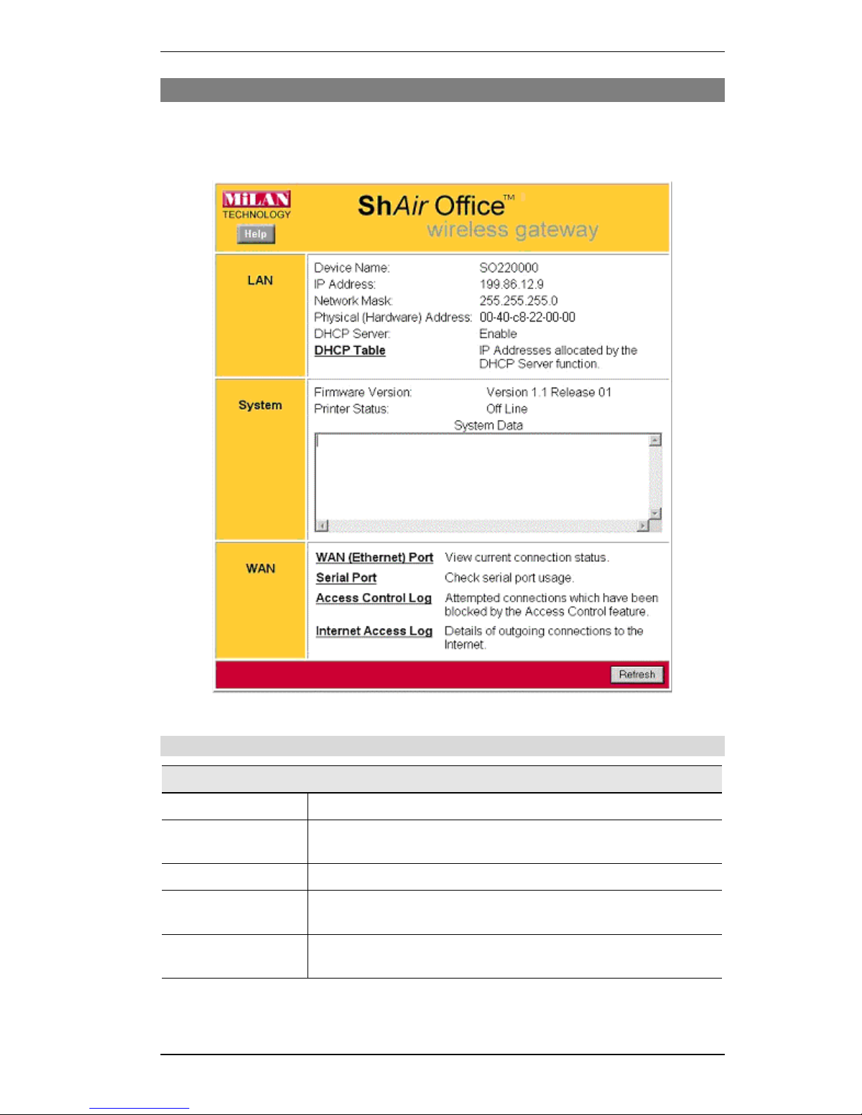
Status Screen
Use the
Status
link on the main menu to view this screen.
The
LAN Status
link on the menu will result in a screen like the example below.
Figure 7: Status Screen
Data - Status Screen
LAN
Device Name
This shows the name of the device.
IP Address
The IP Address of this device, as seen by other devices on the
Internal LAN.
Network Mask
The Network Mask (Subnet Mask) for the IP Address above.
Physical Address
The "Hardware" address of this device, as seen by other devices on
the Internal LAN.
DHCP Server
This shows the status of the DHCP Server function. The value will
be "Enabled" or "Disabled".

Configuration
21
DHCP Table
Use this link to view the IP Addresses which have been allocated to
LAN devices, or the Dial-in user, by the DHCP Server function.
The DHCP Table contains the following data:
•
Port
- The port which the DHCP client used to access this
device. Possible values are LAN, WLAN (Wireless LAN), and
RS232 (serial port).
•
IP Address
- The IP Address which has been allocated by the
DHCP server to the DHCP client.
•
Physical (Hardware) Address
- The Physical Address (Hardware Address) of the DHCP client which has been allocated
this IP Address.
•
Status
- Possible Status values are "Leased" (the IP Address is
allocated to the device shown) or "Reserved" (the IP Address is
reserved for this device, but not currently allocated).
"Reserved" entries are generated for the Dial-in User, and for any
PCs for which an IP Address has been reserved. An IP Address can
be reserved for a particular PC using the Access Control - PCs
screen. The Access Control feature is described in Chapter 10.
System
System Data
This is identical to the data shown on a "Diagnostic Printout", and
contains all system information.
Firmware Version
The version of the firmware currently installed in this device.
Printer Status
This shows the status of the printer. Click the "Refresh Screen"
button to update this information.
WAN Links
WAN (Ethernet)
Port
View the WAN (Ethernet) status screen. This screen will vary
according to the connection method used (Direct connection or
PPPoE).
See the following sections
WAN Status - Direct Connection
and
WAN Status - PPPoE
for details.
Serial Port
Check the status of the Serial Port. This screen is also accessible
from the
Serial Port
sub-menu. See Chapter 6 - Serial Port for
details of this screen.
Access Control Log
View details of connection attempts which have been blocked. See
below for more information.
Internet Access Log
View details of outgoing connections to the internet. See below for
more information.

Wireless Gateway User Guide
22
Access Control Log
This log shows connection requests which have been blocked by the Access Control feature
or the built-in NAT Firewall.
Accesses which have been blocked for other reasons (e.g. URL filter, incorrect dial-in password, incorrect WEP settings on the WLAN) are NOT shown in this log. (The "Internet Access
Log" can be used to view connection attempts which have been blocked by the URL filter.)
Data shown in this log is as follows:
•
Port
- The port used to gain access to this device. Possible values are LAN, WAN, WLAN
(Wireless LAN), and RS232 (serial port).
•
Source IP Address
- The IP Address of the PC or device whose access request was
blocked.
•
Physical Address (Hardware Address)
- The hardware address of the PC or device
whose access request was blocked.
•
Name
- If known, the name of the device whose access was blocked. This name is taken
from the Access Control database. For Wireless devices, the name is obtained from the
Wireless Stations list, and so will always match the Physical (Hardware) address.
•
Destination
- The destination of the attempted access. Possible values are "Internet",
"LAN" or "WLAN".
•
"Internet" indicates an attempt by a LAN user, WLAN user, or dial-in user to access
the Internet using a protocol and/or port number which was blocked.
•
"LAN" or "WLAN" indicates a connection attempt from the Internet which was not
allowed. The protocol (TCP or UDP) and port number are shown in braces.
This data is useful if you want the access to be allowed. In this case, you can use this
data to configure the Advanced Internet - User-defined Virtual Servers screen or the
Advanced Internet - Special Applications screen. (In the case of a Special Application,
this log indicates the "Incoming Connection" for the Special Application.)
See Chapter 9 - Advanced Internet for further details of the Virtual Server and Special
Applications features.
Internet Access Log
This log shows details of Internet access by LAN users, WLAN users, or the dial-in user.
Details shown in this log are as follows:
•
Source IP Address
- The IP Address of the LAN user, WLAN user, or dial-in user making
the connection request.
•
Destination
- The requested Internet IP Address or URL. Normally, the IP Address will be
shown. But if the URL Filter feature is Enabled, the URL will be displayed.
For details on using the URL Filter, refer to Chapter 9 - Advanced Internet.
•
Blocked
- This will indicate "Yes" if the connection attempt was blocked by the URL
Filter. Otherwise, this will be blank.
Configuration
23
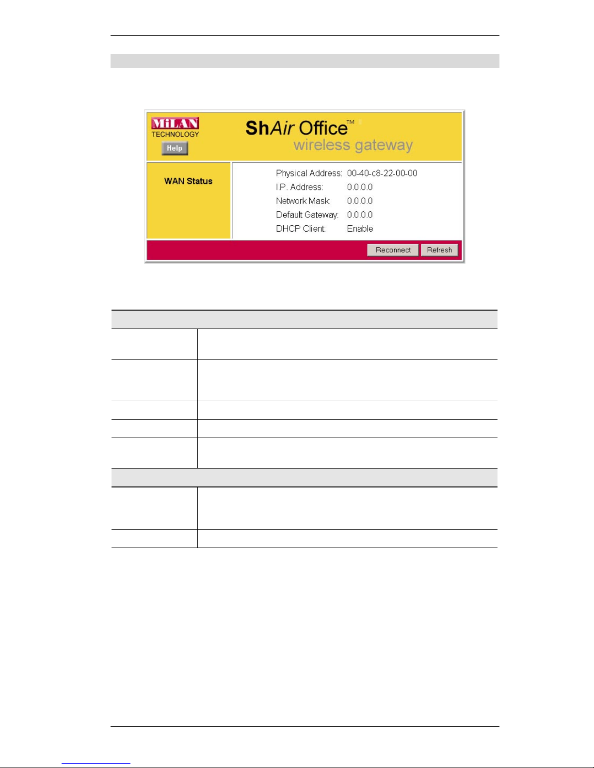
WAN Status – Direct Connection
If the WAN (Ethernet) port is using PPPoE, then clicking the WAN Status link on the Status
screen will reveal a screen like the following.
Figure 8: WAN Status – Direct Connection
Data
WAN Status
Physical Address
The "Hardware" address of this device, as seen by other devices on the
WAN.
IP Address
The IP Address of this device, as seen by devices on the WAN.
(This device has 2 IP Addresses; one for the local LAN, and another
for the WAN port.)
Network Mask
The Network Mask for the above IP Address.
Default Gateway
IP address of the Router/Gateway on the WAN port.
DHCP Client
Displays "Enabled" or "Disabled", indicating whether this device is
acting as a DHCP client on the external LAN or WAN.
Buttons
Reconnect
Use this button if the connection seems to have been lost, and no data is
being transferred. (This button has no effect unless acting as a DHCP
Client.)
Refresh
Update the data on screen.
Wireless Gateway User Guide
24
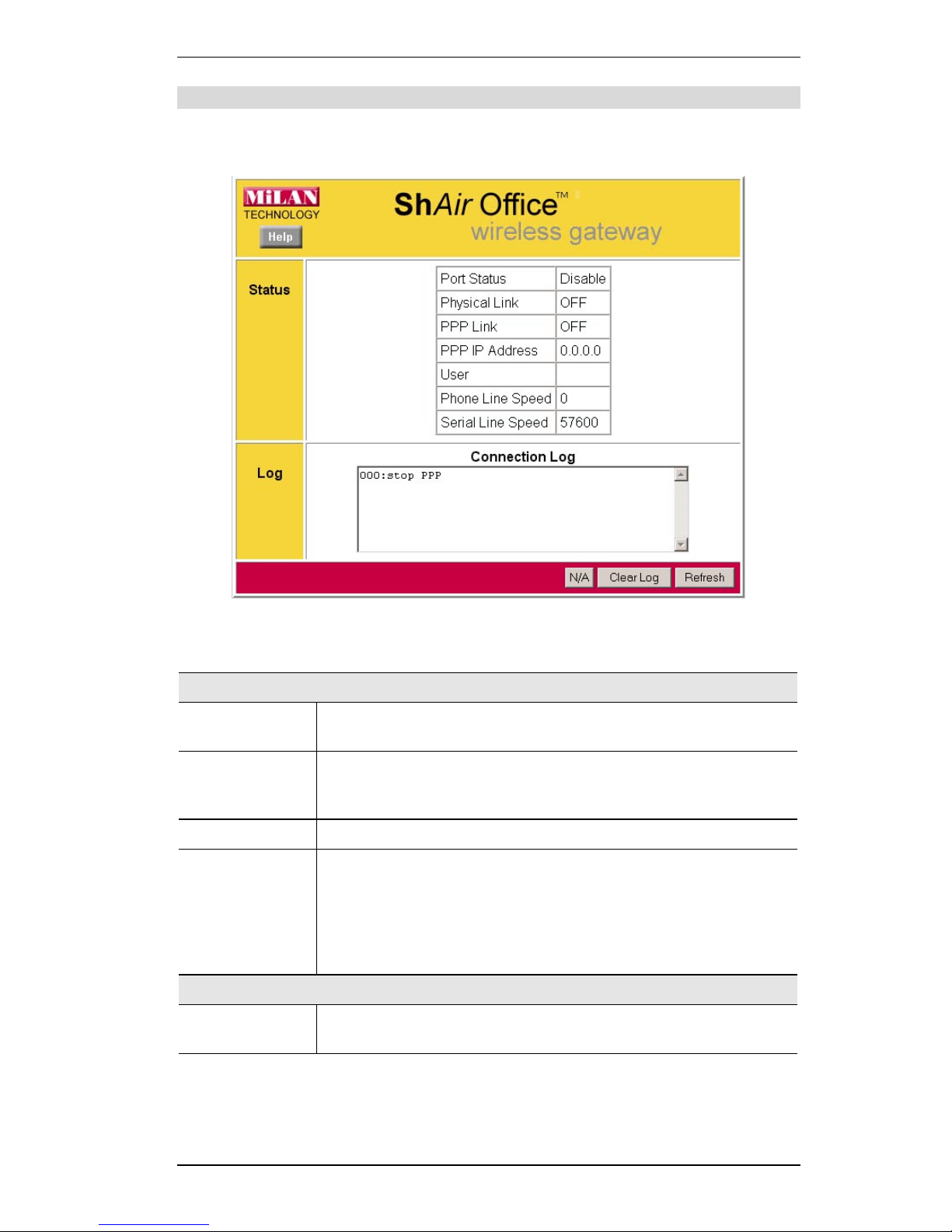
WAN Status – PPPoE
If the WAN (Ethernet) port is using PPPoE, then clicking the WAN Status link on the Status
screen will reveal a screen like the following.
Figure 9: WAN Status – PPPoE
Status Data
WAN Status
Physical Address
The "Hardware" address of this device, as seen by other devices on the
WAN.
IP Address
The IP Address of this device, as seen by devices on the WAN.
(This device has 2 IP Addresses; one for the local LAN, and another
for the WAN port.)
Network Mask
The Network Mask (Subnet Mask) for the IP Address above.
PPPoE Link
Status
This indicates whether or not the connection is currently established.
If the connection does not exist, the
Connect
button can be used to
establish a connection.
If the connection currently exists, the
Disconnect
button can be used to
break the connection.
Connection Log
Log Data
This shows status messages relating to the existing connection. The
most common messages are listed in the following table.

Configuration
25
Buttons
Connect
Disconnect
N/A
If not connected, this button will display "Connect" and can be used to
establish a connection to your ISP
If connected to your ISP, this button will display "Disconnect" and can
be used to hang up the connection.
If PPPoE is not configured, this button will display "N/A" (not applicable).
Clear Log
Delete all data currently in the Log. This will make it easier to read new
messages.
Refresh
Contact this device and update the Log data.
Connection Log Messages
Message Description
Connect on
Demand
Connection attempt has been triggered by the "Connect on Demand" setting.
Manual connection Connection attempt started by the "Connect" button.
Reset physical
connection
Preparing line for connection attempt.
Connecting to remote
server
Attempting to connect to the ISP's server.
Remote Server
located
ISP's Server has responded to connection attempt.
Start PPP Attempting to login to ISP's Server and establish a PPP connection.
PPP up successfully Able to login to ISP's Server and establish a PPP connection.
Idle time-out reached The connection has been idle for the time period specified in the
"Idle Time-out" field. The connection will now be terminated.
Disconnecting The current connection is being terminated, due to either the "Idle
Time-out" above, or "Disconnect" button being clicked.
Error: Remote Server
not found
ISP's Server did not respond. This could be a Server problem, or a
problem with the link to the Server.
Error: PPP Connection failed
Unable to establish a PPP connection with the ISP's Server. This
could be a login problem (name or password) or a Server problem.
Error: Connection to
Server lost
The existing connection has been lost. This could be caused by a
power failure, a link failure, or Server failure.
Error: Invalid or
unknown packet type
The data received from the ISP's Server could not be processed.
This could be caused by data corruption (from a bad link), or the
Server using a protocol which is not supported by this device.

26
Chapter 4
PC Configuration
This Chapter details the PC Configuration required on the local ("Internal")
LAN.
Overview
For each PC, the following may to be configured:
•
TCP/IP network settings
•
Internet Access configuration
•
Network printer
•
Wireless configuration
Windows Clients
This section describes how to configure Windows clients for:
•
Internet access via the Wireless Gateway
•
Printing using the printer attached to the Wireless Gateway.
•
Remote Dial-in access to the modem attached to the Wireless Gateway's serial (RS232)
port.
The first step is to check the PC's TCP/IP settings.
The Wireless Gateway uses the TCP/IP network protocol for all functions, so it is essential that
the TCP/IP protocol be installed and configured on each PC.
TCP/IP Settings
If using the default Wireless Gateway settings, and the default Windows 95/98 TCP/IP
settings, no changes need to be made.
•
By default, the Wireless Gateway will act as a DHCP Server, automatically providing a
suitable IP Address to each PC when the PC boots.
•
The default Windows 95/98 TCP/IP setting is to act as a DHCP client.
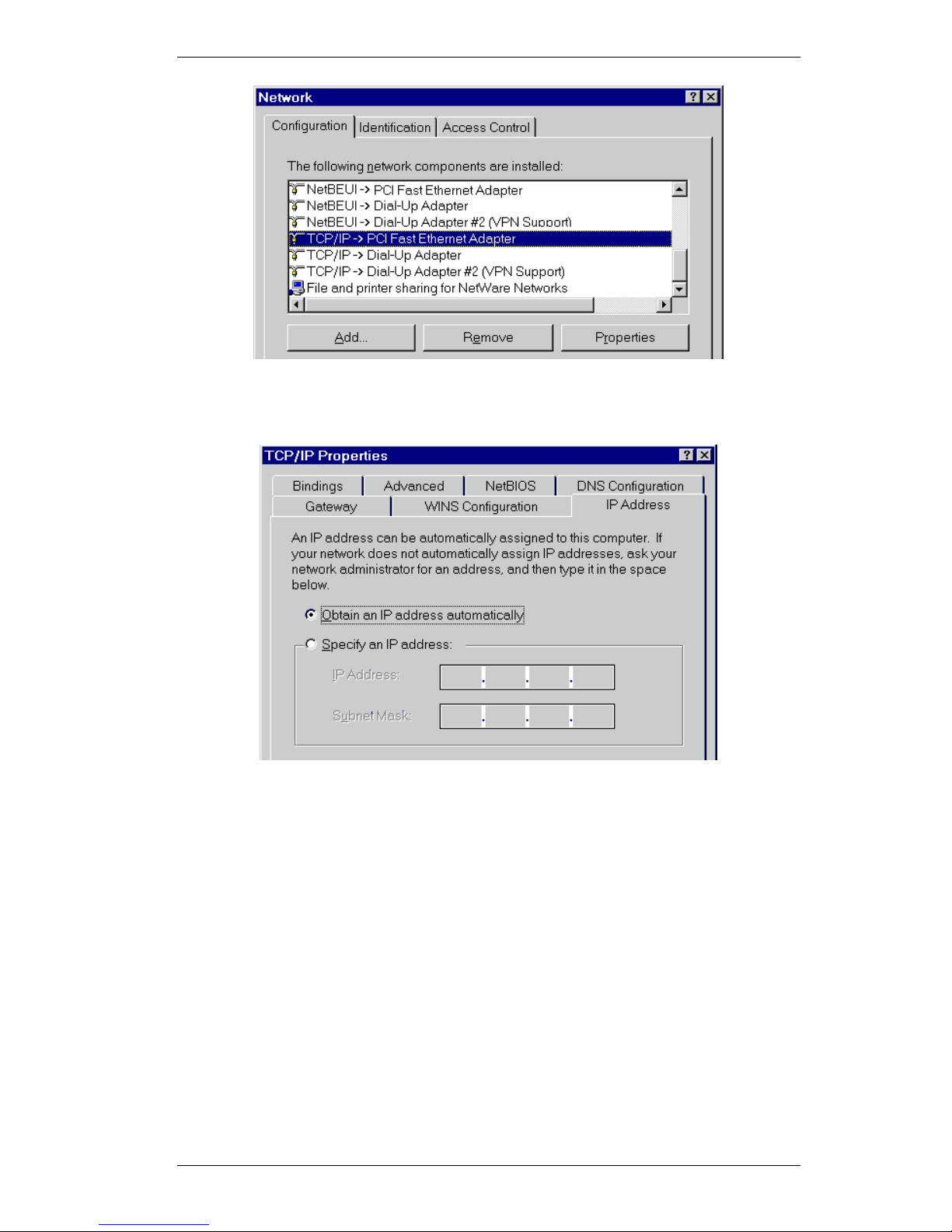
To check your PC's TCP/IP Settings:
1. Select Control Panel - Network. You should see a screen like the following:
4
PC Configuration
27
Figure 10: Network Configuration
2. Select the TCP/IP protocol for your network card.
3. Click on the Properties button. You should then see a screen like the following.
Figure 11: IP Address (Win 95)
Ensure your TCP/IP settings are correct, as follows:
Using DHCP
To use DHCP, select the radio button Obtain an IP Address automatically. This is the default
Windows settings.
Restart your PC to ensure it obtains an IP Address from the Wireless Gateway.
Using “Specify an IP Address”
•
If your PC is already configured, do NOT change the settings on the IP Address tab shown
in Figure 11 above.
•
On the Gateway tab, enter the Wireless Gateway's IP address in the New Gateway field and
click Add. Your LAN administrator can advise you of the IP Address they assigned to the
Wireless Gateway.
 Loading...