

MiLAN MIL-SM8TAF1GPA Management Manual
Management Guide
7 10/100/1000BASE-T (RJ-45) Ports
Plus 1 Combination (RJ-45/SFP) Ports
MIL-SM8TAF1GPA


i
Regulatory Approval
- FCC Class A
- UL60950
- CSA C22.2 No. 60950
- EN60950-1
- CE
- EN55022 Class A
- EN55024
Canadian EMI Notice
This Class A digital apparatus meets all the requirements of the Canadian
Interference-Causing Equipment Regulations.
Cet appareil numerique de la classe A respecte toutes les exigences du Reglement sur le
materiel brouilleur du Canada.
European Notice
Products with the CE Marking comply with both the EMC Directive (89/336/EEC) and the
Low Volt age Directive (73/23/EEC) issued by the Commission of the European Community
Compliance with these directives imply conformity to the following European Norms:
EN55022 (CISPR 22) - Radio Frequency Interference
EN61000-X - Electromagnetic Immunity
EN60950-1 - Product Safety
Five-Year Limited Warranty
Transition Networks warrants to the original consumer or purchaser that each of it's
products, and all components thereof, will be free from defects in material and/or
workmanship for a period of five years from the original factory shipment date. Any
warranty hereunder is extended to the original consumer or purchaser and is not
assignable.
Transition Networks makes no express or implied warranties including, but not limited to,
any implied warranty of merchantability or fitness for a particular purpose, except as
expressly set forth in this warranty. In no event shall Transition Networks be liable for
incidental or consequential damages, costs, or expenses arising out of or in connection
with the performance of the product delivered hereunder. Transition Networks will in no
case cover damages arising out of the product being used in a negligent fashion or
manner.
Trademarks
The MiLAN logo and Transition Networks trademarks are registered trademarks of
Transition Networks in the United States and/or other countries.
To Contact Transition Networks
For prompt response when calling for service information, have the following information
ready:
- Product serial number and revision
- Date of purchase
- Vendor or place of purchase

ii
You can reach Transition Networks technical support at:
E-mail: techsupport@transition.com
Telephone: +1.800.260.1312 x 200
Fax: +1.952.941.2322
Transition Networks
10900 Red Circle Drive
Minnetonka, MN 55343
United States of America
Telephone: +1.800.526.9267
Fax: +1.952.941.2322
http://www.milan.com
info@transition.com
© Copyright 2008 Transition Networks

i
Contents
Chapter 1: Introduction 1-1
Description of Software Features 1-1
Chapter 2: Initial Configuration 2-1
Chapter 3: Configuring the Switch 3-1
Using the Web Interface 3-1
Navigating the Web Browser Interface 3-1
Home Page 3-1
Configuration Options 3-2
Panel Display 3-3
Main Menu 3-3
Web Configuration 3-5
Displaying Status Overview 3-5
Showing Port Statistics 3-8
Displaying the System Name 3-9
Setting the Switch’s IP Address 3-9
Configuring the Logon Password 3-11
Tools 3-11
Port Configuration 3-13
Storm Control 3-14
Port Mirroring 3-15
Cable Diagnostic 3-16
Trunk Membership 3-17
Trunk Configuration 3-18
LACP Setup 3-19
LACP Status 3-20
VLAN Settings 3-21
802.1X 3-24
LLDP 3-27
LLDP Neighbor Table 3-28
SNMP 3-29
POE 3-30
Switch Power Status 3-30
Appendix A: Software Specifications A-1
Software Features A-1
Management Features A-2
Standards A-2

Contents
ii
Management Information Bases A-2
Appendix B: Troubleshooting B-1
Forgot or Lost Password B-1
Changing a PC’s IP Address B-1

iii
Tables
Tables
Table 3-1 Web Page Configuration Buttons 3-2
Table 3-2 Switch Main Menu 3-3
Table 3-3 Port Statistics 3-8

iv
Tables

Figures
v
Figures
Figure 3-2 Front Panel Indicators 3-3
Figure 3-3 Switch Information 3-7
Figure 3-4 Port Statistics 3-8
Figure 3-5 System Name 3-9
Figure 3-6 LAN Settings 3-10
Figure 3-7 Password Settings 3-11
Figure 3-8 Reset to Factory Defaults 3-12
Figure 3-9 Upgrade Firmware 3-12
Figure 3-10 Upload/Download Configuration 3-13
Figure 3-11 Restart Switch 3-13
Figure 3-12 Port Configuration 3-14
Figure 3-13 Port Broadcast Control 3-15
Figure 3-14 Port Mirroring 3-16
Figure 3-15 Cable Diagnostics 3-17
Figure 3-16 Trunk Membership 3-18
Figure 3-17 Trunk Configuration 3-18
Figure 3-18 LACP Port Configuration 3-19
Figure 3-19 LACP Status Overview 3-20
Figure 3-20 VLAN Settings 3-22
Figure 3-21 VLAN Group Settings 3-23
Figure 3-22 VLAN Settings 3-24
Figure 3-23 802.1X Configuration 3-26
Figure 3-24 802.1X Statistics 3-27
Figure 3-27 SNMP Configuration 3-29

Figures
vi

1-1
Chapter 1: Introduction
The MIL-SM8TAF1GPA is a web-managed Gigabit PoE switch that delivers
performance and control to your network. It provides 8 full-duplex 1000BASE-T
ports that significantly improve network performance and boost throughput using
features configured through a web-based management interface. With 16 Gigabits
of throughput bandwidth, this switch provides an effective solution to meeting the
growing demands on your network.
Description of Software Features
The switch provides a wide range of advanced performance enhancing features.
Flow control eliminates the loss of packets due to bottlenecks caused by port
saturation. Broadcast storm suppression prevents broadcast traffic storms fr om
engulfing the network. CoS priority queueing ensures the minimum delay for moving
real-time multimedia data across the network. While multicast filtering provides
support for real-time network applications. Some of the management features are
briefly described below.
Configuration Backup and Restore – You can save the current configuration
settings to a file on the web management station, and later download this file to
restore the switch configuration settings.
Authentication – The switch supports port-based user authentication via the IEEE
802.1X protocol. This protocol uses the Extensible Authentication Protocol over
LANs (EAPOL) to request user credentials from the 802.1X client, and then verifies
the client’s right to access the network via an authentication server.
Port Configuration – You can manually configure the speed, duplex mode, and
flow control used on specific ports, or use auto-negotiation to detect the connection
settings used by the attached device. Use the full-duplex mode on ports whenever
possible to double the throughput of switch connections. Flow control is enabled to
control network traffic during periods of congestion and prevent the loss of packets
when port buffer thresholds are exceeded. The switch supports flow control based
on the IEEE 802.3x standard.
Port Mirroring – The switch can unobtrusively mirror traffic from any port to a
monitor port. You can then attach a protocol analyzer or RMON probe to this port to
perform traffic analysis and veri fy connection integrity.
Port Trunking – Ports can be combined into an aggregate connection. Trunks can
be manually set up or dynamically con figured usi ng I EEE 802. 3ad Link Ag gregat io n
Control Protocol (LACP). The additional ports dramatically increase the throughput
across any connection, and provide redundancy by taking over the load if a port in
the trunk should fail. The switch supports up to 4 trunks.

Introduction
1-2
Broadcast Storm Cont rol – Broa dcast s uppress ion preve nts broadcast traffic f rom
overwhelming the network. When enabled on a port, the level of broadcast traffic
passing through the port is restricted. If broadcast traffic rises above a pre-defined
threshold, it will be throttled until the level falls back beneath the threshold.
Static Addresses – A static address can be assigned to a specific interface on this
switch. Static addresses are bound to the assigned interface and wi ll not be moved.
When a static address is seen on another interface , the address will be ignored and
will not be written to the address table. Static addresses can be used to provide
network security by restricting access for a known host to a specific port.
IEEE 802.1D Bridge – The switch suppo rts IEEE 802.1D transparent bridging. The
address table facilitates data switching by learning addresses, and then filtering or
forwarding traffic based on this information. The address table supports up to 8K
addresses.
Store-and-Forward Switching – The switch copies each frame into its memory
before forwarding them to another port. This ensures that all frames are a standard
Ethernet size and have been verified for accuracy with the cyclic redundancy check
(CRC). This prevents bad frames from entering th e network and wasting bandwidth.
To avoid dropping frames on congest ed ports, the switch provides 400 KB for frame
buffering. This buffer can queue packets awaiting transmission on congested
networks.
Virtual LANs – The switch support s up to 64 VLANs. A V irtu al LAN is a collec tion of
network nodes that share the same collision domain regardless of their physical
location or connection point in the network. The switch supports tagged VLANs
based on the IEEE 802.1Q standard. Ports can be manually assigned to a specific
set of VLANs. This allows the switch to restri ct traffic to the VLAN groups to which a
user has been assigned. By segmenting your network into VLANs, you can:
• Eliminate broadcast storms which severely degrade performance in a flat network.
• Simplify network management for node changes /moves by remotely configuring
VLAN membership for any port, rather than having to manually change t he
network connection.
• Provide data security by restricting all traf fic to the originating VLAN.
Power-over-Ethernet (PoE) – The switch’s eight RJ-45 ports support the IEEE
802.3af PoE standard that enables DC power to be supplied to attached devices
over wire pairs in the connecting Ethernet cable. Any 802.3af compliant device
attached to a port can directly draw power from the switch over the Ethernet cable
without requiring its own sep arate power source. This capability gives network
administrators centralized power con trol for devices such as IP phon es and wireless
access points, which translates into greater network availability.
A maximum PoE power budget for the switch (power available to all switch ports) is
defined so that power can be centrally managed, preventing overload conditions at
the power source. If the power demand from devices connected to the switch
exceeds the power budget, the switch uses port power priority settings to limit the
supplied power.

2-1
Chapter 2: Initial Configuration
To make use of the management features of your MIL-SM8TAF1GP A, you must first
configure it with an IP address that is compatibl e with the network it is bein g installed
in. This should be done before you permanently install the switch in the network.
Follow this procedure:
1. Place the switch close to the PC that you i ntend to use fo r configuration. It helps
if you can see the front panel of the switch whi le working on your PC.
2. Connect the Ethernet port of your PC to any port on the front panel of the
switch. Connect power to the switch and verify that you have a link by check ing
the front-panel LEDs.
3. Check that your PC has an IP address on the same subnet as the switch. The
default IP address of the switch is 192.168.2 .10 and the subnet mask is
255.255.255.0, so the PC and switch are on the same subnet if they both have
addresses that start 192.168.2.x. If the PC and switch are not on the same
subnet, you must manually set the PC’ s IP add ress to 192.16 8.2.x (where “x” i s
any number from 1 to 255, except 10). If you are unfamiliar with this process,
see “Changing a PC’s IP Address” on page B-1.
4. Open your web browser and enter the address http://1 92.168.2.10. If your PC is
properly configured, you will see the login page of the switch. If you do not see
the login page, repeat step 3.
5. Enter the default password “admin” and click on the Login but ton.
6. From the menu, click on SYSTEM, then click on LAN Settings. On the LAN
Settings page, enter the new IP address, Subnet Mask and Gateway IP
Address for the switch, then click on the APPLY button.
No other configuration changes are required at this stage, but it is recommended
that you change the administrator’s password before l ogging out. To change the
password, click SYSTEM, Password, and then fill in all the fields on the Password
Settings page before clicking on the APPLY button.

Initial Configuration
2-2

3-1
Chapter 3: Configuring the Switch
Using the Web Interface
This switch provides an embedded HTTP web agent. Using a web browser you can
configure the switch and view statist ics to monitor network activity. The web agent
can be accessed by any computer on the network using a standard web browser
(Internet Explorer 5.5 or above, or Mozilla Firefox 1.0 or above).
Prior to accessing the switch from a web browser, be sure you have first performed
the following tasks:
1. Configure the switch with a valid I P address, subnet mask, an d default gateway.
(Defaults: IP address 192.168.2.10; Subnet mask 255.255.255.0; Gateway
0.0.0.0)
2. Set a new password using the web interface. (Default: “admin”). Access to the
web interface is controlled by the password. See “Configuring the Logon
Password” on page 3-11.
Note:
If you cannot remember the switch's IP address, you can restore the original
settings by following the procedure described in the “Troubleshooting” section.
Navigating the Web Browser Interface
To access the web-browser interface you must first enter a password. The user has
read/write access to all configuration parameters and statistics. The default
password for the switch is “admin.”
Note:
If user input is not detected within five minutes, the current session is terminated.
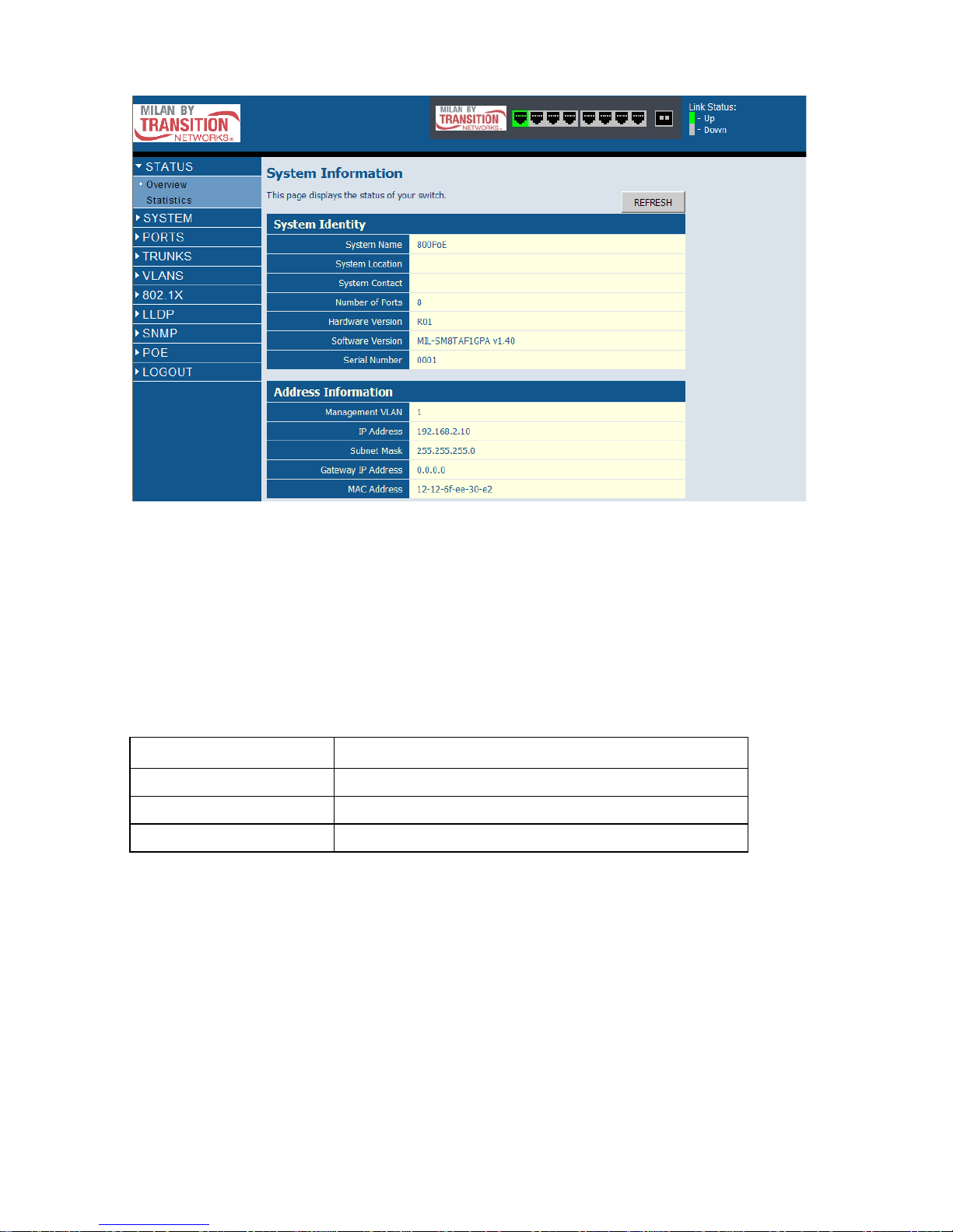
Home Page
When your web browser connects with the switch’s web agent, the home page is
displayed as shown below. The home page displays the Main Menu on the left side
of the screen and System Information on the right side. The Main Menu links are
used to navigate to other menus, and display configuration parameters and
statistics.
Configuring the Switch
3-2
Figure 3-1 Home Page
Configuration Options
Configurable parameters have a di alog box or a drop-down list . Once a configuratio n
change has been made on a page, be sure to click on the Apply button to confirm
the new setting. The following table summarizes the web page configuration
buttons.
Note:
To ensure proper screen refresh, be sure that Internet Explorer is configured as
follows: Under the menu “Tools / Internet Options / General / Temporary Internet
Files / Settings,” the setting for item “Check for newer versions of stored pages”
should be “Every visit to the page.”
Table 3-1 Web Page Configuration Buttons
Button Action
Apply Sets specified values to the system.
Cancel Discards all changes and restores current values.
Help Links directly to web help.
 Loading...