

MiLAN MIL-SM808G User Manual
8 Port 100BASE-FX
Plus One GBIC
Intelligent Fiber Switch
MIL-SM808G
USER GUIDE

Regulatory Approval
- FCC Class A
- UL 1950
- CSA C22.2 No. 950
- EN60950
- CE
- EN55022 Class A
- EN55024
Canadian EMI Notice
This Class A digital apparatus meets all the requirements of the Canadian Interference-Causing Equipment Regulations.
Cet appareil numerique de la classe A respecte toutes les exigences du Reglement sur le materiel brouilleur du Canada.
European Notice
Products with the CE Marking comply with both the EMC Directive (89/336/EEC) and the Low Voltage Directive (73/23/EEC)
issued by the Commission of the European Community Compliance with these directives imply conformity to the following
European Norms:
- EN55022 (CISPR 22) - Radio Frequency Interference
- EN61000-X - Electromagnetic Immunity
- EN60950 (IEC950) - Product Safety
MiLAN Technology warrants to the original consumer or purchaser that each of it's products, and
all components thereof, will be free from defects in material and/or workmanship for a
period of five years from the original factory shipment date. Any warranty hereunder is
extended to the original consumer or purchaser and is not assignable.
MiLAN Technology makes no express or implied warranties including, but not limited to, any
implied warranty of merchantability or fitness for a particular purpose, except as expressly set
forth in this warranty. In no event shall MiLAN Technology be liable for incidental or
consequential damages, costs, or expenses arising out of or in connection with the
performance of the product delivered hereunder. MiLAN Technology will in no case cover damages
arising out of the product being used in a negligent fashion or manner.
Trademarks
The MiLAN logo and MiLAN Technology trademarks are registered trademarks of MiLAN Technology in the
United States and/or other countries.
To Contact MiLAN Technology
For prompt response when calling for service information, have the following information ready:
- Product serial number and revision
- Date of purchase
- Vendor or place of purchase
You can reach MiLAN Technology technical support at:
E-mail: support@milan.com
Telephone: +1.408.744.2751
Fax: +1.408.744.2771
MiLAN Technology
1329 Moffett Park Drive
Sunnyvale, CA 94089
United States of America
Five-Year Limited Warranty
Telephone: +1.408.744.2775
Fax: +1.408.744.2793
http://www.milan.com
info@milan.com
© Copyright 2003 MiLAN Technology P/N: 90000407 Rev. A
ii

Table of Contents
1. Introduction
Features
Intelligent Management Features
Package Contents
Management Methods
Console and Telnet Management
Web-based Management
SNMP Network Management
2. Hardware Description
Front Panel
LED Indicators
Rear Panel
Desktop Installation
3. Network Application
Segment Application
4. Network Configuration
Connecting a Terminal or PC to the Console Port
Console - Menu
4-1. Main Menu
4-2. Status and Counters
4-2-1. Port Status
4-2-2. Port Counters
4-2-3. System Information
4-3. Switch Static Configuration
4-3-1. Administration Configuration
4-3-1-1. Device Information
4-3-1-2. IP Configuration
4-3-1-3. Change Username
4-3-1-4. Change Password
4-3-2. Port / Trunk Configuration
4-3-3. Port Mirroring Configuration
4-3-4. VLAN Configuration
4-3-4-1. VLAN Configure
4-3-4-2. Create a VLAN Group
4-3-4-3. Edit / Delete a VLAN Group
4-3-5. Priority Configuration
4-3-6. MAC Address Configuration
4-3-6-1. Static MAC Address
4-3-6-2. Filtering MAC Address
4-3-7. Misc. Configuration
4-3-7-1. Port Security
4-3-7-2. MAC Age Interval
4-3-7-3. Broadcast Storm Filtering
4-3-7-4. Max Bridge Transmit Delay Bound
4-4. Protocol Related Configuration
4-4-1. STP
4-4-1-1. STP Enable
4-4-1-2. System Configuration
4-4-1-3. STP Port Configuration
iii

4-4-2. SNMP
4-4-2-1. System Options
4-4-2-2. Community Strings
4-4-2-3. Trap Managers
4-4-3. GVRP
4-4-4. LACP
4-4-4-1. Aggregator Setting
4-4-4-2. State Activity
4-4-4-3. LACP Status
4-5. Switch Reboot
4-6. Updating Firmware using the Console Port
5. Web-Based Management
5-1. Web Management Home Overview
5-2. Port Status
5-3. Port Statistics
5-4. Administrator
5-4-1. IP Address
5-4-2. Switch Settings
5-4-2-1. Basic
5-4-2-2. Advanced
5-4-3. Console Port Information
5-4-4. Port Controls
5-4-5. Trunking
5-4-5-1. Aggregator Setting
5-4-5-2. Aggregator Information
5-4-5-3. State Activity
5-4-6. Filter Database
5-4-6-1. IGMP Snooping
5-4-6-2. Static MAC Address
5-4-6-3. Port Security
5-4-6-4. MAC Filtering
5-4-7. VLAN Configuration
5-4-7-1. Basic
5-4-7-2. Port VID
5-4-8. Set Spanning Tree
5-4-9. Port Mirroring
5-4-10. SNMP
5-4-11. Security Manager
5-4-12. TFTP Update Firmware
5-4-13. Configuration Backup
5-4-13-1. TFTP Restore Configuration
5-4-13-2. TFTP Backup Configuration
5-4-14. Reset System
5-4-15. Reboot
6. Technical Specifications
7. Troubleshooting
Incorrect connections
Diagnostic LED Indicators
iv
1.
Introduction
The MIL-SM808G managed compact desktop switch is an ideal solution
for a Fiber network infrastructure. It provides wire-speed, Fast Ethernet
switching providing high-performance data transfer. The switch features
a store-and-forward architecture with auto-learning of source addresses
with an 8K-entry MAC address table.
Figure 1-1. The MIL-SM808G switch
The switch provides eight switched 100Mbps Fast Ethernet Fiber ports
and one GBIC slot for a GBIC transceiver. The fiber port connectors are
available in either SC (single mode or multi-mode) or ST (multi-mode).
With built-in Web-based Management, managing and configuring the
switch is simplified. The Web Browser may be used to configure and
manage the network, from cabinet level management to port level
control and monitoring. Use of a mouse replaces typing of command
strings. The switch can also be managed via Telnet, Console, or SNMP
Management.
1

Features
Conforms to IEEE802.3u, IEEE802.3z and IEEE802.3x
Ethernet Standards
Eight 100Mbps Fast Ethernet Fiber ports and one GBIC port
One Console port on the front for switch software configuration
Half-duplex mode for back pressure and flow control for full-
duplex
Store-and-forward switching architecture
Automatic address learning, address migration
8K-entry MAC address table
2Mbit memory buffer sharing
Non-blocking full wire speed performance
LED-indicators for Power, LNK/ACT, FDX/COL,
LNK/ACT(GBIC)
19-inch design for desktop or rackmount
Intelligent Management Features
Web-based management
SNMP network management
Console and Telnet management
Port Based VLAN and IEEE 802.1q Tag VLAN, and VLAN
group up to 256 , VLAN ID up to 4K
IEEE 802.1ad Port Trunk and IEEE 802.3ad Port Trunk with
LACP( Link Aggregation Control protocol) supported
IEEE 802.1d Spanning Tree
MIB II ( RFC1213 ) supported
IGMP Querier, IGMP Snooping, up to 256 IGMP groups
Quality of Service (system provides 8 levels) and Class of
service (per port Hi/Low Queue)
Port Mirroring
Broadcast Filtering
Static MAC Address filtering
Port Security
GVRP
2

Package Contents
Unpack the contents of the package and verify them against the
checklist below.
MIL-SM808G Switch
Power Cord
Four Rubber Feet
RS-232 cable
User Guide ( CD Manual)
Warranty Card
If any item is missing or damaged, please contact your local dealer for
service.
Management Methods
The MIL-SM808G switch series support the following management
methods:
Console and Telnet Management
Web-based Management
SNMP Network Management
Console and Telnet Management
Console Management is done through the RS-232 Console Port.
Managing the switch in this method requires a direct connection
between a PC and the switch. Telnet management requires a network
connection. The default IP address is 192.168.1.77 with a subnet mask
of 255.255.255.0. This default address can be used to login and change
the configuration using Telnet.
Web-based Management
The switch provides an embedded HTML web server residing in flash
memory. It offers advanced management features and allows users to
manage the switch from anywhere on the network through a standard
browser such as Microsoft Internet Explorer or Netscape.
3

SNMP Network Management
SNMP ( Simple Network Management Protocol ) provides a means to
monitor and control network devices, and to manage configurations,
statistic collection, performance, and security.
4
2.
Hardware Description
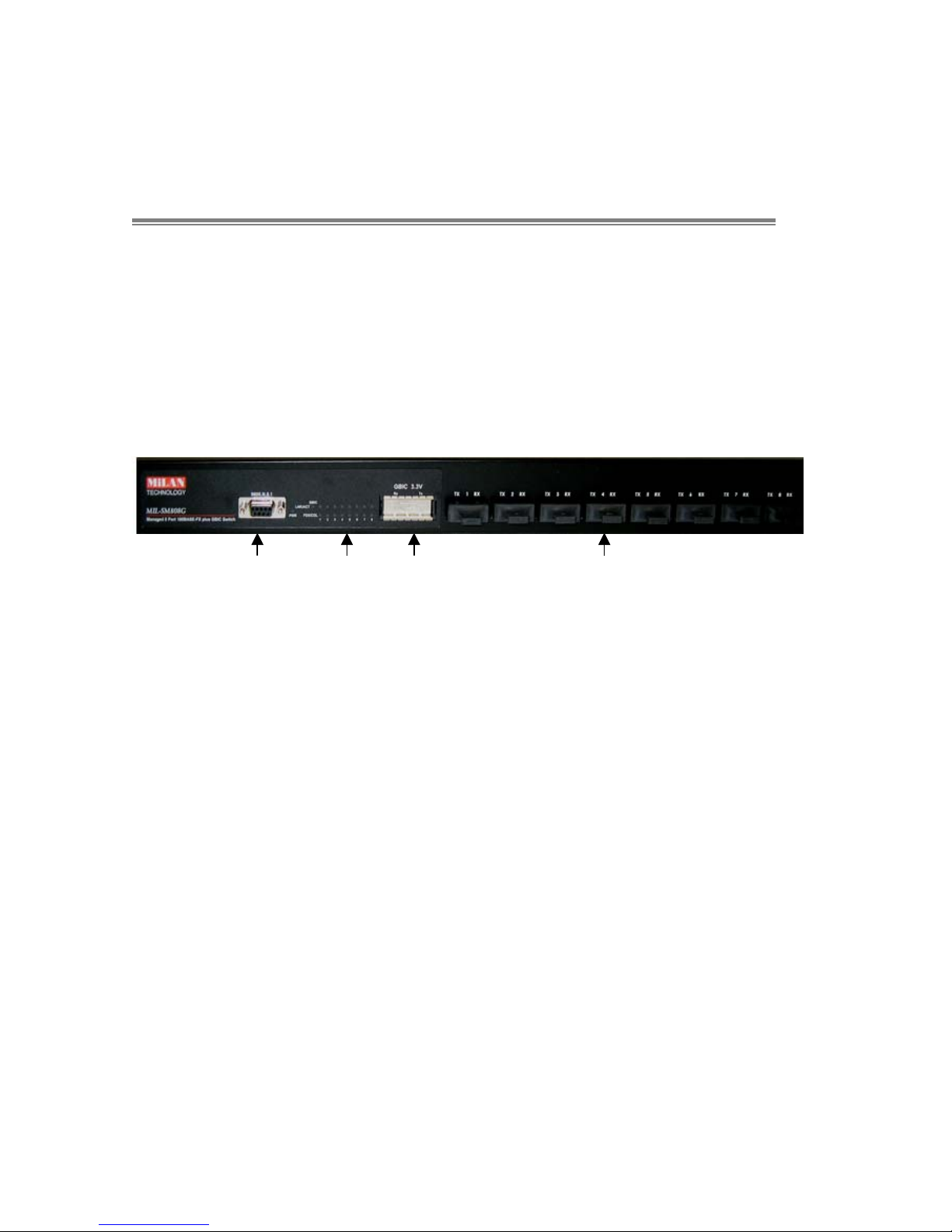
Front Panel
The Front Panel of the MIL-SM808G switch series consists of eight
100Mbps Fast Ethernet Fiber ports, one GBIC port, one console port,
one LED-Indicator for Power, one LED-Indicator (LNK/ACT) for the
GBIC port and two LED-Indicators (LNK/ACT, FDX/COL) for each Fiber
port.
Console LED GBIC Fast Ethernet
Port Indicators Port Fiber Ports
Figure 2-1. Front Panel for MIL-SM808G
100BASE-FX Fiber Ports: The MIL-SM808G comes with eight
SC connectors (multi-mode or single mode) or eight ST connectors
(multi-mode).
GBIC Port: The MIL-SM808G supports the 3.3V model Gigabit
Transceiver for Gigabit SX or LX connector.
Console Port: Console management can be done through the
Console Port. It requires a direct connection between the switch and
an end station (PC) via a RS-232 cable.
5

LED Indicators
Figure 2-2. LED Indicators
There are two LED-Indicators (LNK/ACT, FDX/COL) for each Fiber port,
one LED-Indicator (LNK/ACT) for the GBIC port and one LED-Indicator
for power. The following table provides descriptions of the LED statuses
and meaning. They provide a real-time indication of systematic
operation status.
LED Status Color Description
Power On Green Power On
The port is successfully connecting with
a device.
The port is receiving or transmitting
data.
LNK /
ACT
On Green
Blinks Green
Off No device attached.
The port is operating in full-duplex
mode and device is attached.
Collision of Packets is occurring on the
port.
Half-duplex mode or no device
attached.
FDX /
COL
On Orange
Blinks Orange
Off
Table 2-1. The description of LED Indicators
6
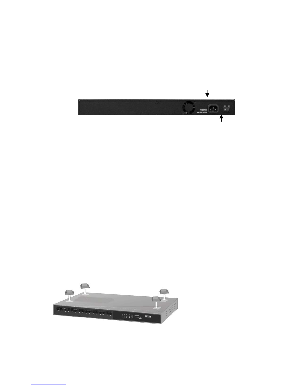
Rear Panel
The 3-pronged power plug and the power on/off switch are located at
the Rear Panel of the MIL-SM808G switch, as shown in Figure 2-3. The
switches will work with AC in the range 100-240V AC, 50-60Hz.
Power Plug
Power
On/Off
Switch
Figure 2-3. The Rear Panel of the MIL-SM808G Switch
Desktop Installation
Set the switch on a sufficiently large flat space with a power outlet
nearby. The surface where you put your switch should be clean, smooth,
level, and sturdy. Provide enough clearance around the switch to allow
attachment of cables, power cord and air circulation.
Attaching Rubber Feet
A. Make sure the mounting surface on the bottom of the Switch is
grease and dust free.
B. Remove adhesive backing from the rubber feet.
C. Apply the rubber feet to each corner on the bottom of the switch.
These footpads can prevent the Switch from shock/vibration.
Figure 2-4. Attaching Rubber Feet to each corner on the bottom of the
Switch
7

Power On
Connect the power cord to the power socket on the rear panel of the
Switch. Connect the other end of the cord to an appropriate power
outlet. The internal power supply in the switch works with AC in the
voltage range 100-240VAC, frequency 50~60Hz.
Press the power On/Off switch to the On position and check the power
indicator on the front panel to see if power is properly supplied.
8
3.
Network Application
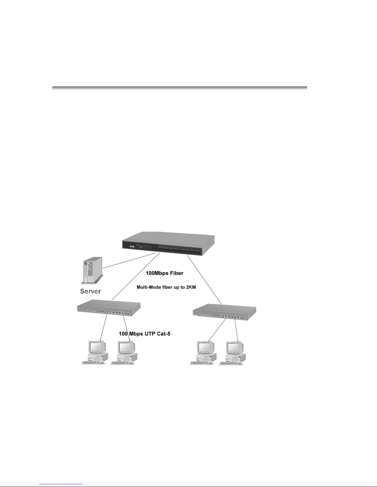
Segment Application
For enterprise networks where large data broadcasts are constantly
processed, this switch is suitable for department users to connect to the
corporate backbone.
You can use the MIL-SM808G switch to connect PCs, workstations, and
servers to each other by connecting these devices directly to the switch.
You can also use any of the Fiber ports of MIL-SM808G to connect with
another Switch or Hub to interconnect each of your small switched
workgroups to form a larger and long distance switched network.
MIL-SM808G
Figure 3-1. Use the MIL-SM808G switch fiber ports to extend the distance between
workgroups
MIL-SM801P
9
4.
Network Configuration
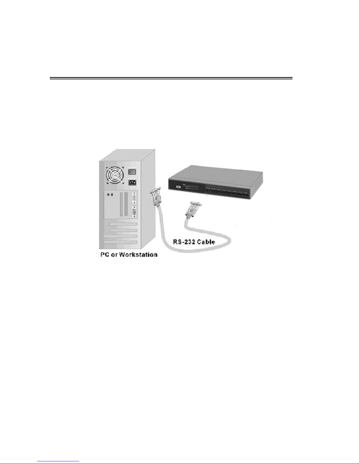
Connecting a Terminal or PC to the Console Port
Console management involves the administration of the switch via a
direct connection to the RS-232 console port. This port is a female DB-9
connector. From the main menu of the console program, the user has
access to manage the functions of the switch.
Figure 4-1. Connecting the switch to a terminal via RS-232 cable
Use the supplied RS-232 cable to connect a terminal or PC to the
console port. The terminal or PC to be connected must support the
terminal emulation program.
10
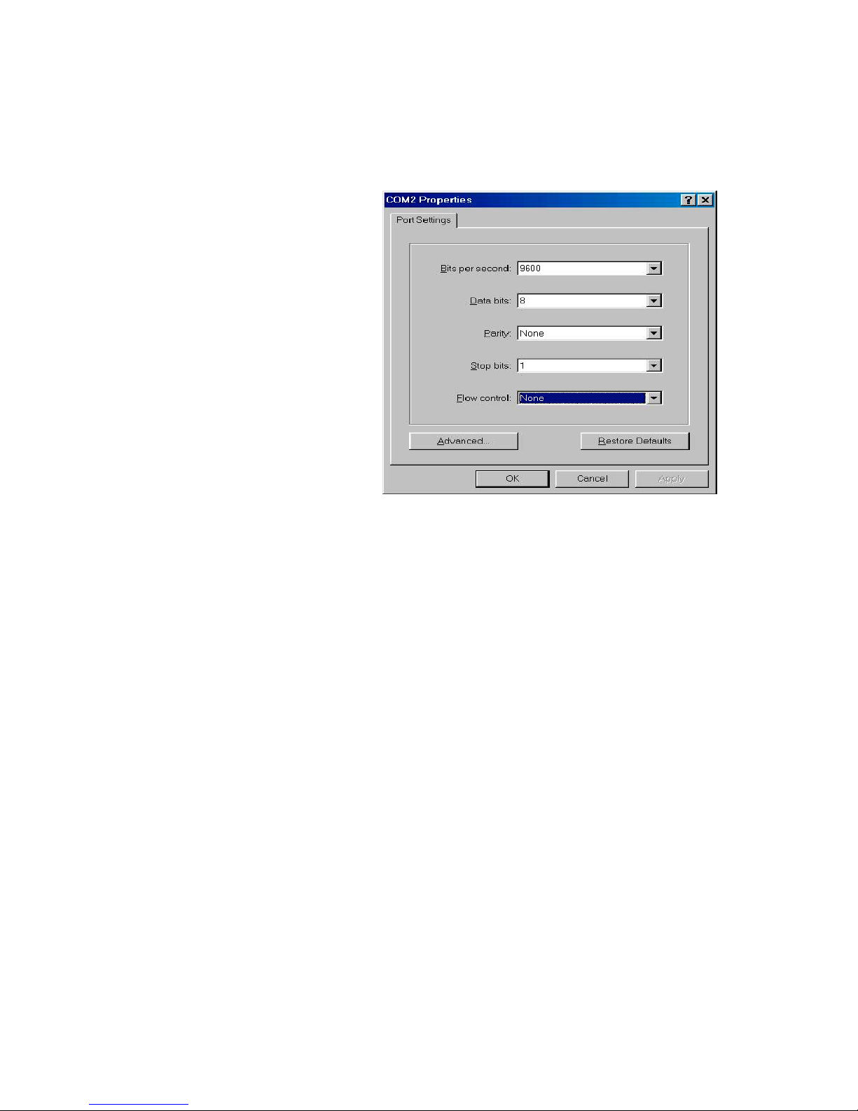
After the connection between Switch and PC is finished, turn on the PC
and run a terminal emulation program or Hyper Terminal to match the
following default characteristics of the console port:
Baud Rate: 9600 bps
Data Bits: 8
Parity: none
Stop Bits: 1
Flow Control: None
Figure 4-2. The settings of communication parameters
After you have entered the parameter settings, press the “ Enter “ Key
and the Main Menu of console management appears.
Console – Menu
1. The switch also provides a serial interface to manage and monitor the
switch. The user can follow the Console Port Information provided by
the web to use the Windows HyperTerminal program to link the switch.
2. Type the user name and password to login. The default user name is
“root”; the default password is “root”.
3. The timeout on the console port is 60 seconds. If no action is taken
on the console screen for one minute, the program reverts back to the
logon screen and a new login is necessary in order to continue.
4. The switch is shipped with a default IP address of 192.168.1.77. The
default subnet mask is 255.255.255.0.
11
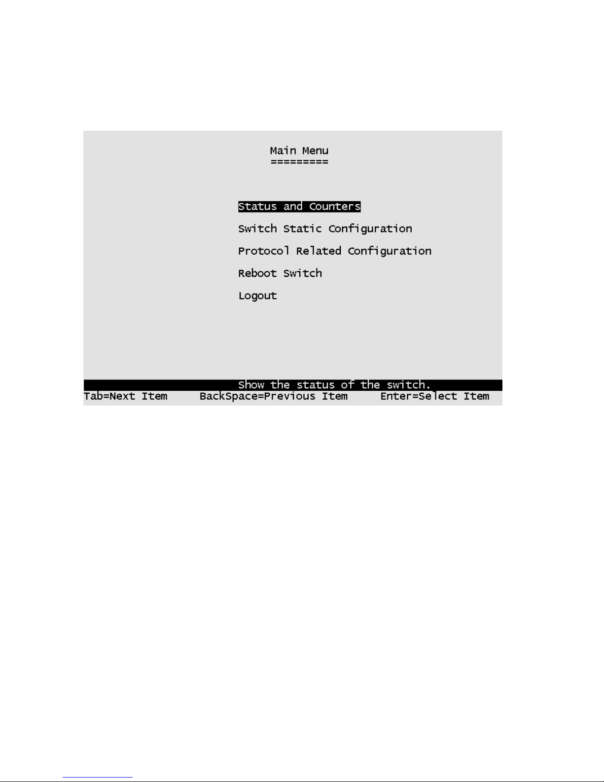
4-1 Main Menu
There are five items for selection as follows:
Status and Counters: Shows the status of the switch.
Switch Static Configuration: Menus to configure the switch.
Protocol Related Configuration: Configures protocol features.
Reboot Switch: Restarts the system or resets the switch to the default
configuration.
Logout: Exits the menu line program.
<Control Key>
The control keys listed below are provided in all menus:
Tab: Moves the cursor to next item.
Backspace: Moves the cursor to previous item.
Enter: Selects item.
Space: Toggles selected item to next configuration.
12
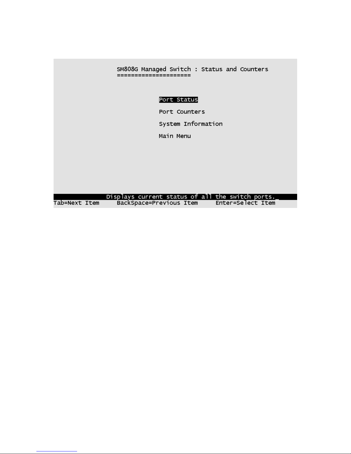
4-2. Status and Counters
Press the Tab or Backspace key to choose action menu, and then press the
Enter key to select the item.
13
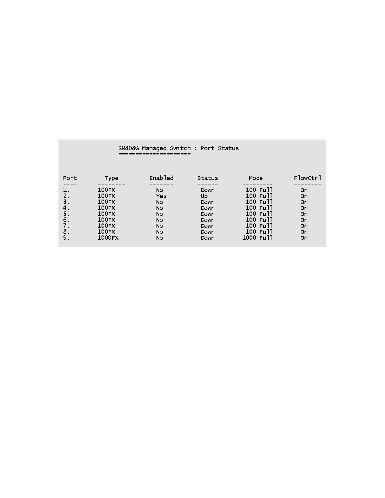
4-2-1. Port Status
Type: Displays the port type of either 100Mbps or 1000Mbps.
Enabled: A port that is enabled will be displayed as “Yes”. A port that is
disabled will be displayed as “No”.
Status: Displays the port's link. “Down” the port has no link, and “Up” the
port has a link with the remote device.
Mode: Displays the port speed and duplex mode.
FlowCtrl: Displays the flow control for the port as being either on or off.
Actions->
Press the Tab or Backspace key to choose action menu, and then press the
Enter key to select item.
<Quit>: Exits the port status page and returns to previous menu.
14
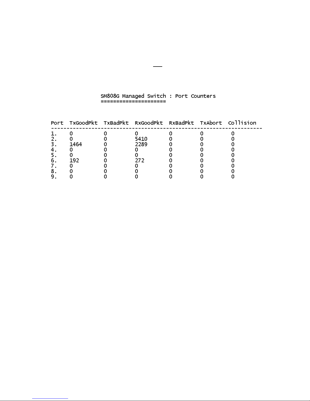
4-2-2. Port Counters
The following information provides a view of the current data packet
information of the unit. The screen is not automatically updated. To see
updated statistics, exit the menu and re-enter.
Actions->
Press the Tab or Backspace key to choose action menu, and then press
Enter key to select item
<Quit>: Exits the port status page and returns to previous menu.
<Reset All>: Sets all counters to 0.
15
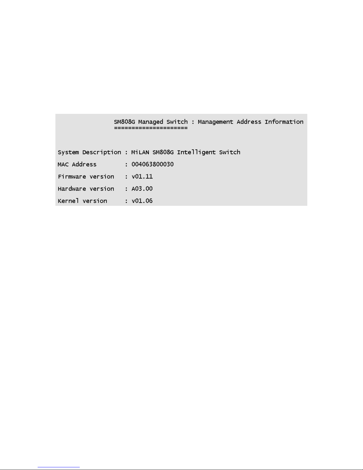
4-2-3. System Information
System Description: Displays the name of the device.
MAC Address: The unique hardware address assigned by manufacturer.
Firmware Version: Displays the switch’s firmware version.
Hardware Version: Displays the switch’s Hardware version.
Kernel version: Displays Boot PROM version.
16
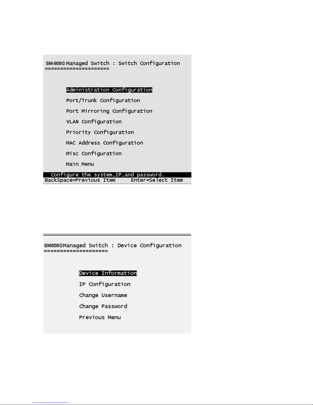
4-3. Switch Static Configuration
Press the Tab or Backspace key to choose action menu, and then press the
Enter key to select item.
4-3-1. Administration Configuration
17

4-3-1-1. Device Information
Device Name: 10 characters can be used to give the switch a unique name
in order to distinguish it on the network. After configuration this name will
show at the top of each menu screen.
Device Content: 32 characters can be used to describe devices attached.
Device Location: 32 characters can be used to give a location of the switch.
Device Description: 32 characters can be used to describe the switch.
Actions->
<Edit>: Configures all items. When finished, pressing ESC returns to the
action menu line.
<Save>: Saves all configured values.
<Quit>: Exits the device information page and returns to previous menu.
18
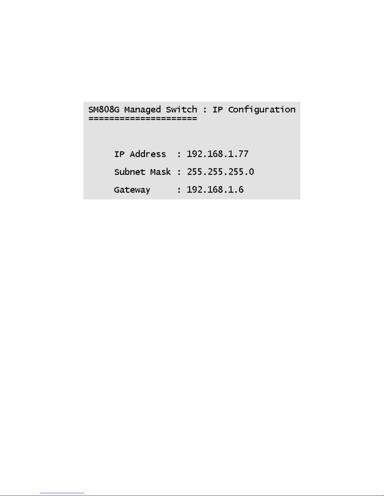
4-3-1-2. IP Configuration
This menu enables the user to change the default settings of the IP address,
subnet mask and gateway. Rebooting the switch is necessary to have the
configuration change take affect.
Actions->
<Edit>: Configures all items. When finished, pressing ESC returns to the
action menu line.
<Save>: Saves all configured values.
<Quit>: Exits the IP configuration page and returns to previous menu.
Note: Always restart the computer after finishing the setup.
19
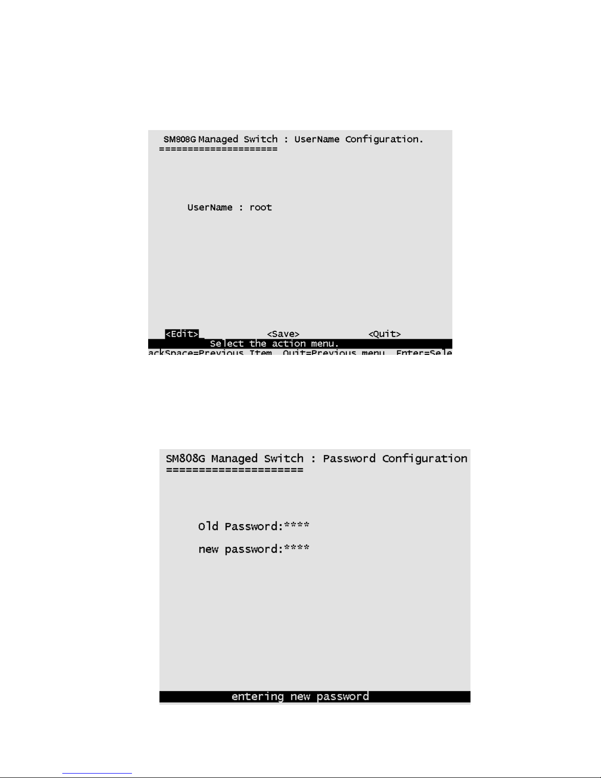
4-3-1-3. Change Username
Use this screen to change the User Name. The default user name is root.
4-3-1-4. Change Password
Use this screen to change the Password. The default password is root.
20
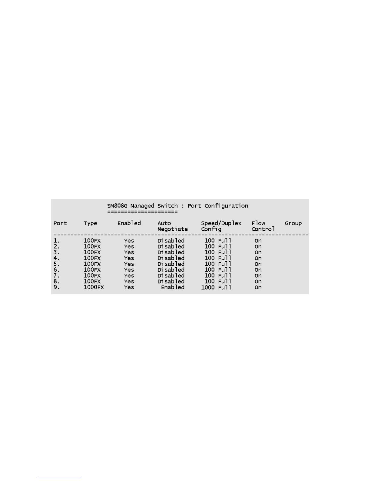
4-3-2. Port / Trunk Configuration
This page can change every port status and configure trunk groups.
Press TAB key to change the configuration of each item.
1. Enabled: User can disable or enable the port. Port 9 is always enabled.
2. Auto Negotiate: Ports 1 to 8 (100Mbps Fiber) are disabled, Port 9 (GBIC
port) is enabled.
3. Speed/Duplex Config: Ports 1 to 8 (100 Mbps Fiber port) can be set for
full-duplex or half-duplex mode. Port 9 (GBIC port) is fixed at 1000Mbps
full-duplex mode.
4. Flow Control: User can set flow control function to be on or off for ports
1 to 8. Flow control for Port 9 (GBIC port) is fixed at enabled (on).
5. Group: User can set trunk groups for ports 1 to 8. There are four possible
trunk groups. Port 9 is not available for trunk groups.
Actions->
<Quit>: Exits the port configuration page and returns to previous menu.
<Edit>: Configures all items. When finished, pressing ESC returns to the
action menu line.
<Save>: Saves all configured values.
21
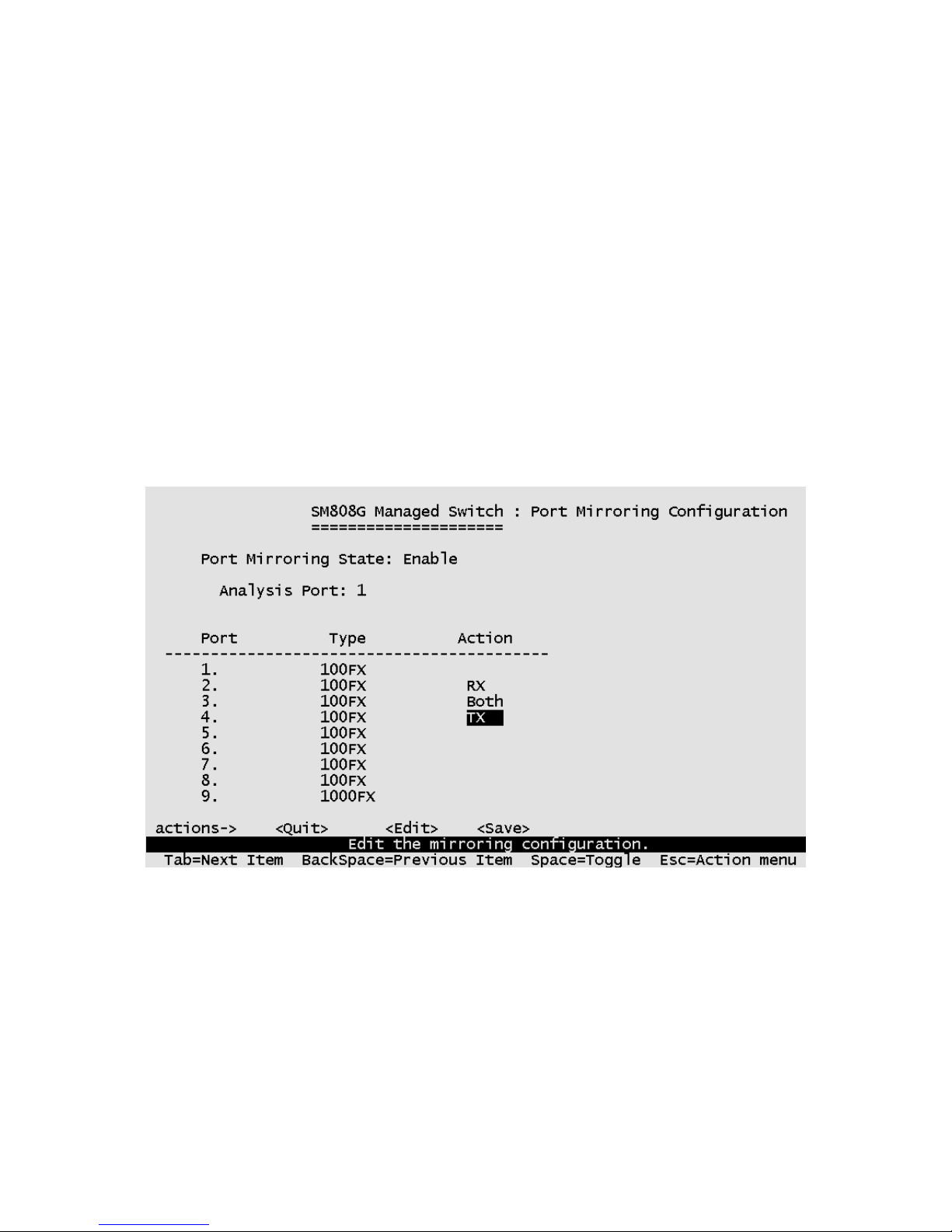
4-3-3. Port Mirroring Configuration
Port mirroring is a method for monitoring traffic in switched networks. Traffic
through ports can be monitored by one specific port. The traffic being
received or transmitted by the monitored ports will be duplicated into the
monitoring port.
Press the Space key to change the configuration of an item.
1. Port Mirroring State: Select enable or disable.
2. Analysis Port: The port to which all traffic to be mirrored will be sent.
3. Port: The port(s) you want to monitor. All monitored port traffic will be
copied to the monitoring port. You can select a maximum of 8 ports to
monitor in the switch. User can choose to monitor RX frames only or TX
frames only or both RX and TX frames at the Action command line.
Actions->
<Quit>: Exits the port monitoring configuration page and returns to previous
menu.
<Edit>: Configures all items. When finished, pressing ESC returns to the
action menu line.
<Save>: Saves all configured values.
22
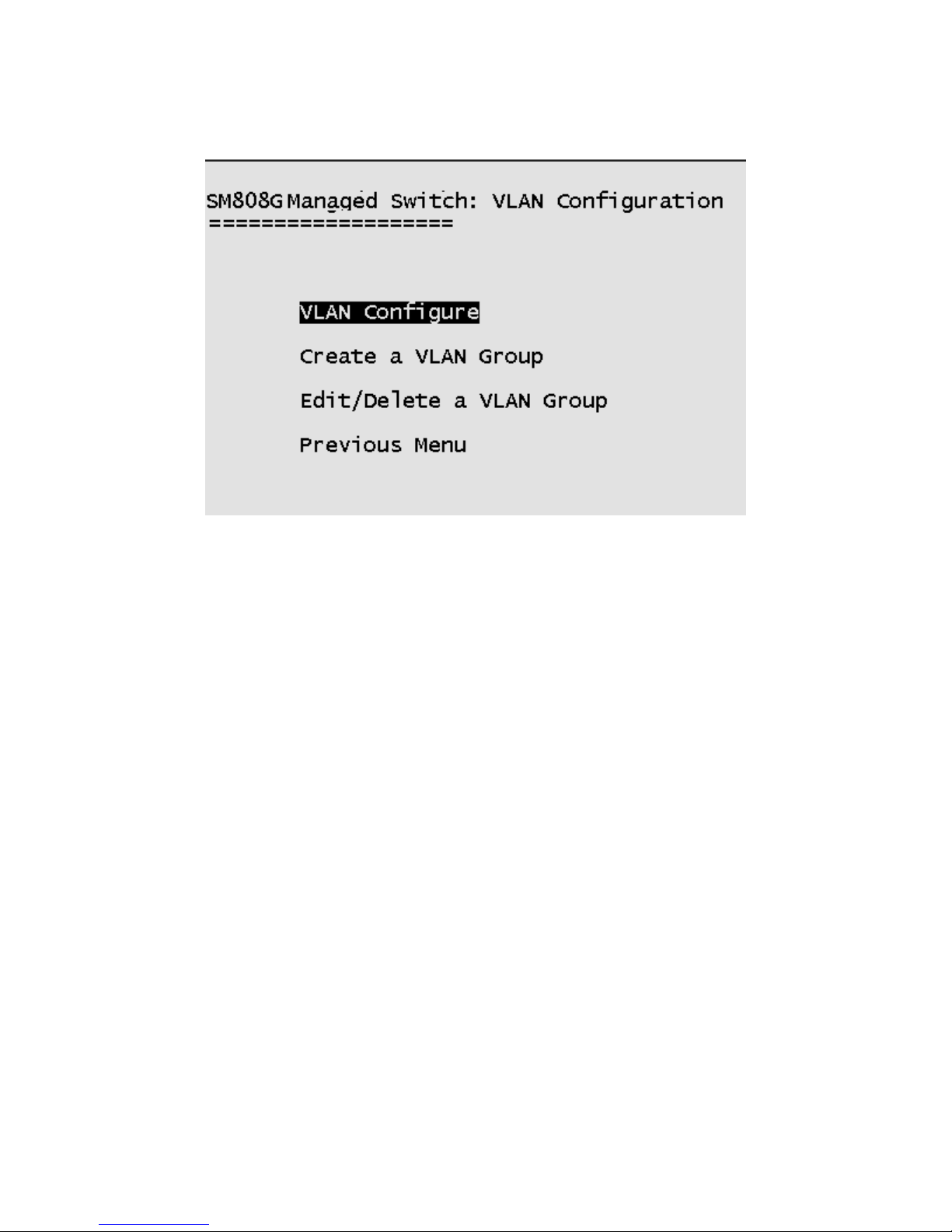
4-3-4. VLAN Configuration
All ports are automatically placed in VLAN 1, the default VLAN. To create new
VLANs, use the Create a VLAN Group menu and add a VLAN. Make sure
when you enter a VLAN name you do not leave spaces. For example VLAN2
is correct; VLAN 2 will give an error. The VLAN name can be any 15
alphanumeric characters. Special characters are not allowed.
23
 Loading...