

MiLAN MIL-SM800, MIL-SM801 User Manual
Managed 8 port 10/100 Switches
MIL-SM800 and
MIL-SM801 with additional fiber port
USER GUIDE

Regulatory Approval
- FCC Class A
- UL 1950
- CSA C22.2 No. 950
- EN60950
- CE
- EN55022 Class A
Canadian EMI Notice
This Class A digital apparatus meets all the requirements of the Canadian Interference-Causing Equipment Regulations.
Cet appareil numerique de la classe A respecte toutes les exigences du Reglement sur le materiel brouilleur du Canada.
European Notice
Products with the CE Marking comply with both the EMC Directive (89/336/EEC) and the Low Voltage Directive
(73/23/EEC) issued by the Commission of the European Community Compliance with these directives imply conformity to
the following European Norms:
- EN55024
- EN55022 (CISPR 22) - Radio Frequency Interference
- EN61000-X - Electromagnetic Immunity
- EN60950 (IEC950) - Product Safety
MiLAN Technology warrants to the original consumer or purchaser that each of it's products, and
all components thereof, will be free from defects in material and/or workmanship for a
period of five years from the original factory shipment date. Any warranty hereunder is
extended to the original consumer or purchaser and is not assignable.
MiLAN Technology makes no express or implied warranties including, but not limited to, any
implied warranty of merchantability or fitness for a particular purpose, except as expressly set
forth in this warranty. In no event shall MiLAN Technology be liable for incidental or
consequential damages, costs, or expenses arising out of or in connection with the
performance of the product delivered hereunder. MiLAN Technology will in no case cover damages
arising out of the product being used in a negligent fashion or manner.
Trademarks
© 2000 MiLAN, the MiLAN logo and MiLAN Technology are either trademarks or registered
trademarks of Digi International, Inc. in the United States and/or other countries. All other
trademarks are the property of their respective holders.
To Contact MiLAN Technology
For prompt response when calling for service information, have the following information ready:
- Product serial number and revision
- Date of purchase
- Vendor or place of purchase
You can reach MiLAN Technology technical support at:
E-mail: support@milan.com
Telephone: +1.408.744.2751
Fax: +1.408.744.2771
MiLAN Technology
1299 Orleans Drive
Sunnyvale, CA 94089-1138
United States of America
Five-Year Limited Warranty
Telephone: +1.408.744.2775
Fax: +1.408.744.2793
http://www.milan.com
info @ milan.com
© Copyright 2001 MiLAN Technology P/N: 90000382_A

Contents
1. Introduction…….…………….…………….……….……………………………… 1
Features ……………………………………………………....…..…….……..…… 2
Intelligent Management Features ……………………....…………………..…… 2
Package Contents ………………………..………………..……….………...…… 2
Ethernet Switching Technology ………………………..…………………….…… 3
Management Methods ………………………………….……...……………..…… 4
2. Hardware Description ………………..….…...…...……………………. ………… 5
Front Panel ……………………………..……………………...…...…………..…… 5
MIL-SM801 …………………………………………………………………………… 5
MIL-SM801SC with SC Connector …………….………………...………………. 5
MIL-SM801ST with ST Connector ………………………………..………………. 5
MIL-SM801MT with MT-RJ Connector ………..…………………..………….…… 6
MIL-SM801VF with VF-45 Connector …………………………..………………. 6
MIL-SM800………………………………………………………………….………… 6
LED Indicators ………………………………………………………………………. 7
Rear Panel ……………………………………………..……………………………. 8
Desktop Installation ……………………….………………….……..……………… 8
3. Network Configuration …………..…….…….…….………………………………… 9
Connecting a Terminal or PC to the Console Port …………..….....…………….. 9
Assigning IP address ……………...………….………..………....…………………. 10
Secured IP ……………………….…..……………………………………………….. 13
Resetting Factory Defaults (MIL-SM801)………….………..………....……… …… 14
Resetting Factory Defaults (MIL-SM800) )………….………..………....…… …… 15
4. Web-Based Management .………………………………………………. …… ……. 16
System Login ………………………..……………....…………….……..…………… 16
5. System Configuration .…………………………………………………… …………… 18
Network Setting…………………………………………….…...……………………… 18
System Group…………………………………………….…...………………………. 18
Statistics …………………………………………….…...……………………………. 19
Port Config …………………………………….………...………....………………… 20
Speed Config …………………………………….…...………..……….……………. 21
VLAN ………….……………………………….…...…………….……………. ……. 22
Trunking ………………………………………………...…….…....………………… 23
Agent Config …………………………………………………………………………… 24
Boot Methods………….………..………....……………….………..………..…….. 25
6. Technical Specifications .…………………….....…………………………………… 25
7. Troubleshooting .…………………………………..…………………………………. 27
Incorrect connections ...……………………………………………….…………….. 27
Diagnosing LED Indicators ………………………..…………………..……….. ….. 27
Appendix Internet Explorer Setting…….……….…………………………………….. 28
1. Introduction
In today’s society, the ability to communicate quickly and share important data is
essential to our lifestyle. Computer networks have proven to be one of the fastest
methods of communication.
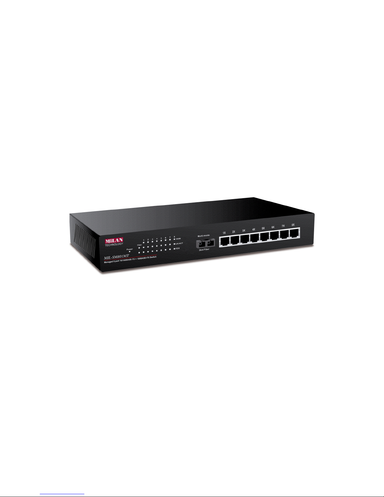
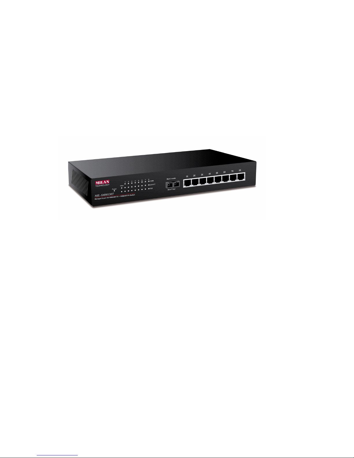
The MIL-SM801 and MIL-SM800 series are compact desktop size switches that are
ideal solutions for small, medium and enterprise networks. The switch provides
wire-speed switching with high-performance, and low-cost connections. Using the
store-and-forward switching method, this switch can auto-learn and store up to 8K
worth of MAC addresses.
Figure 1-1. The MIL-SM801XX
The MIL-SM800 switch provides eight switched auto-sensing 10/100 Mbps RJ-45
Ethernet ports. The MIL-SM801 provides one additional 100BASE-FX fiber port.
The switch will automatically detect the speed of the device that you plug into,
allowing you to use both 10 and 100Mbps devices. The 10Mbps bandwidth will
accommodate 10Mbps workgroup hubs while simultaneously providing the
100Mbps bandwidth needed to accommodate multimedia applications. In addition,
each RJ-45 port supports Auto MDI/MDIX for easy installation.
The MIL-SM801XX switch provides one 100Base-FX fiber port. There are 4 types
of fiber connectors available on the switch. These fiber connectors are SC, ST, MTRJ, VF-45 (multi-mode) and SC (single-mode). The fiber port can be used to
connect to a remote site up to 2 kilometers (multi-mode) or 15~60 kilometers (SC
single- mode).
Both switches include built in Web-based Management. You can easily configure
and monitor the switch through your web browser. You can also use our text base
console program through Telnet, Serial Console, or any SNMP management
system.
1

Features
n Conforms to IEEE 802.3, 802.3u, and 802.3x Ethernet Standards
n Eight auto-sensing 10/100Mbps Ethernet RJ-45 ports
n Automatic MDI/MDIX crossover for each 10Base-T/ 100Base-TX port
n One fixed 100Mbps fiber port (MIL-S801XX)
n One RS-232 for Serial Console management
n Half-duplex mode for back pressure, and full-duplex for flow control
n Store-and-forward switching architecture for abnormal packet filtering
n Automatic address learning, address migration
n 8K-entry MAC address table
n 512KB memory buffer sharing
n Performs non-blocking full wire speed (1.8Gbps)
n LED-indicators for Power, 100M, LK/ACT, FD/COL
n 10-inch desktop size design
Intelligent Management Features
n Web-based management
n SNMP network management
n Console management
n Supports up to nine port based VLAN groups and support for multiple VLANs
on a port
n Port Trunking ( Up to 4 ports ---800Mbps cascade )
n MIB II ( RFC1213 ) supported
n Port Configuration
n Port Disable/Enable Setting
n Auto-negotiation, 100 Full/half-duplex, or 10 Full/half-duplex mode
Package Contents
n MIL-SM801XX or MIL-SM800
n Power cord
n Four rubber feet
n RS-232 cable for console port
n User Guide
2
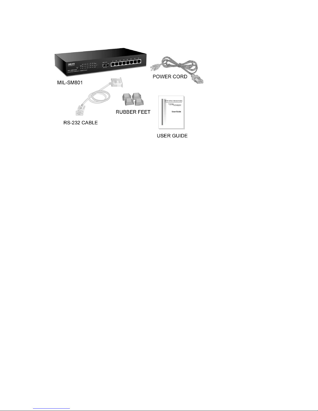
Figure 1-2. Package Contents
Compare the contents of your MIL-SM801XX or MIL-SM800 package with the
standard checklist above. If any item is missing or damaged, please contact your
local dealer for service.
Ethernet Switching Technology
Ethernet Switching Technology dramatically boosted the total bandwidth of a
network, eliminated congestion problems inherent with Carrier Sense Multiple
Access with Collision Detection protocol, and greatly reduced unnecessary
transmissions.
Switches have revolutionized the network world in three major ways. First, by using
a switch you can have two-way, simultaneous transmissions over the same port (full
duplex), essentially doubling the bandwidth. Second, by reducing the collision
domain to a single switched-port “Carrier Sensing” is eliminated. Third, using storeand-forward switching, unnecessary transmissions can be eliminated to avoid
congestion.
Auto-negotiation regulates the speed and duplex of each port, based on the
capability of both devices. Flow-control allows transmission from a 100Mbps node
to a 10Mbps node without loss of data. You may need to disable auto-negotiation
and flow control for some networking operations involving legacy equipment.
Disabling the auto-negotiation is accomplished by fixing the speed or duplex of a
port.
3

Management Methods
The switches support the following management methods:
n Console and Telnet Management
n Web-based Management
n SNMP Network Management
Console and Telnet Management
Console Management is done through the serial Console Port. This method
requires a direct connection between a PC and the switch. Telnet management is
done over the network. Once the switch has an assigned IP address and is on the
network, you can use Telnet to login and make configuration changes.
Web-based Management
The switch provides an embedded HTML web site residing in flash memory. It offers
advanced management features and allows users to manage the switch from
anywhere on the network through a standard browser such as Microsoft Internet
Explorer or Netscape Navigator. For more information, see chapter 6.
SNMP Network Management
SNMP (Simple Network Management Protocol) provides a way to monitor and
control network devices, and to manage configurations, statistic collection,
performance, and security.
4
2. Hardware Description
This section describes the hardware of the managed switches. The switch is compact in
size with eight auto-sensing 10/100Mbps Ethernet RJ-45 ports (MIL-SM800) and one
100Base-FX fiber port (MIL-SM801xx).
Front Panel
The front panel of the MIL-SM801XX series consists of eight auto-sensing 10/100Mbps
Ethernet RJ-45 ports (automatic MDI/MDIX), one 100Base-FX fiber port, and LED
indicators.
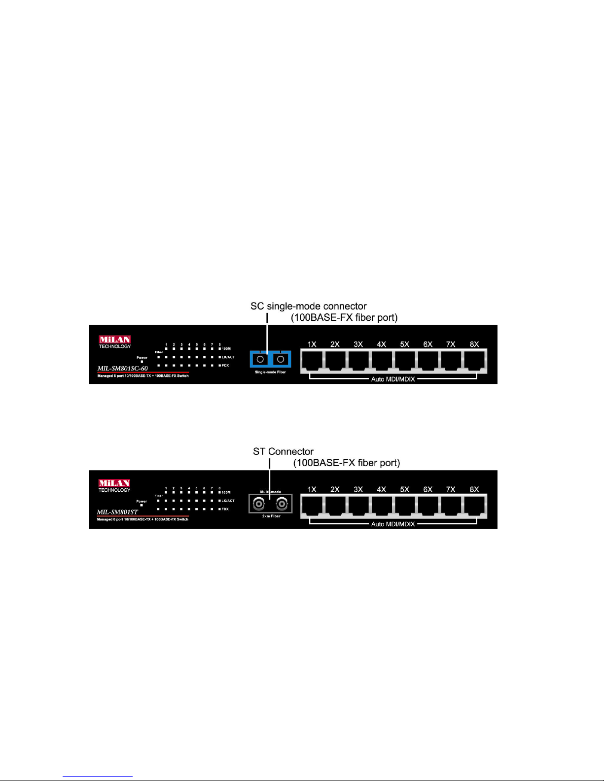
Different front panels of the MIL-SM801XX series are illustrated below. There are four
different types of fiber connectors available for the convenience of your connectivity.
These fiber connectors are SC, (SC single-mode), ST, MT-RJ and VF-45.
Figure 2-3. The Front Panel of the MIL-SM801XX with SC (single mode) connector
Figure 2-4. The Front Panel of the MIL-SM801XX with ST connector
5
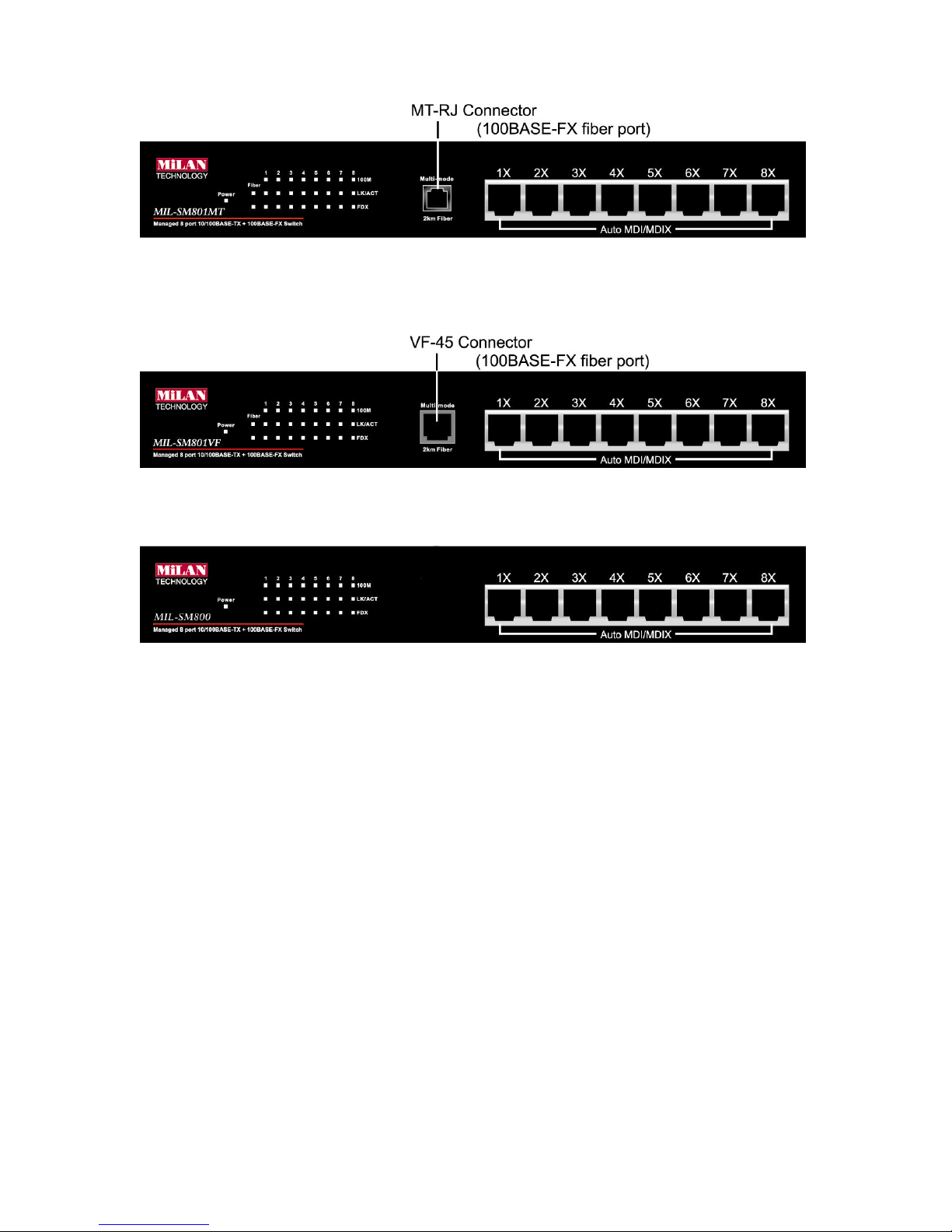
Figure 2-5. The Front Panel of the MIL-SM801XX with MT-RJ connector
Figure 2-6. The Front Panel of the MIL-SM801XX with VF-45 connector
Figure 2-7. The Front Panel of the MIL-SM800
n RJ-45 Ports (Auto MDI/MDIX): Eight 10/100 auto-sensing for 10Base-T or
100Base-TX connections. MDI configuration provides the means to connect to
another hub or switch while MDIX provides connection to a workstation or PC.
n 100Base-FX Fiber Port: There are four connectors available for the MIL-
SM801XX as shown above. The distance for multi-mode fiber cabling can be
up to 2 kilometers, whereas the distance for SC single-mode fiber can be up to
60 kilometers.
6
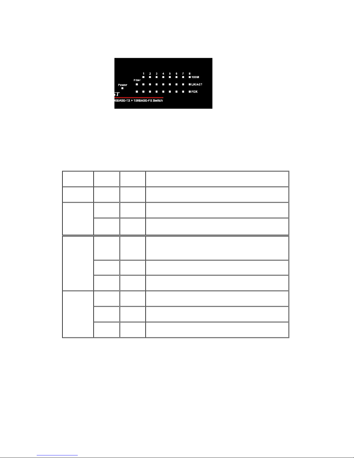
LED Indicators
Figure 2-7. Detail of LED Indicators for the MIL-SM801
There are three LED-indicators (100M, LNK/ACT, FDX/COL) for each UTP port.
The following table provides descriptions of the LED indicators. They provide a realtime indication of operational status.
LED Status Color Description
Power
On Green Power On
On Green The port is operating at the speed of 100Mbps
100M
Off In 10Mbps mode or no device attached
On Green The port is successfully connected to a device
LNK /
ACT
Blinks Green The port is receiving or transmitting data
Off No device attached
On Amber The port is operating in full-duplex mode
FDX /
COL
Blinks Amber Collisions are occurring on the port
Off Half-duplex mode or no device attached
Table 2-1. Description of LED Indicators
7
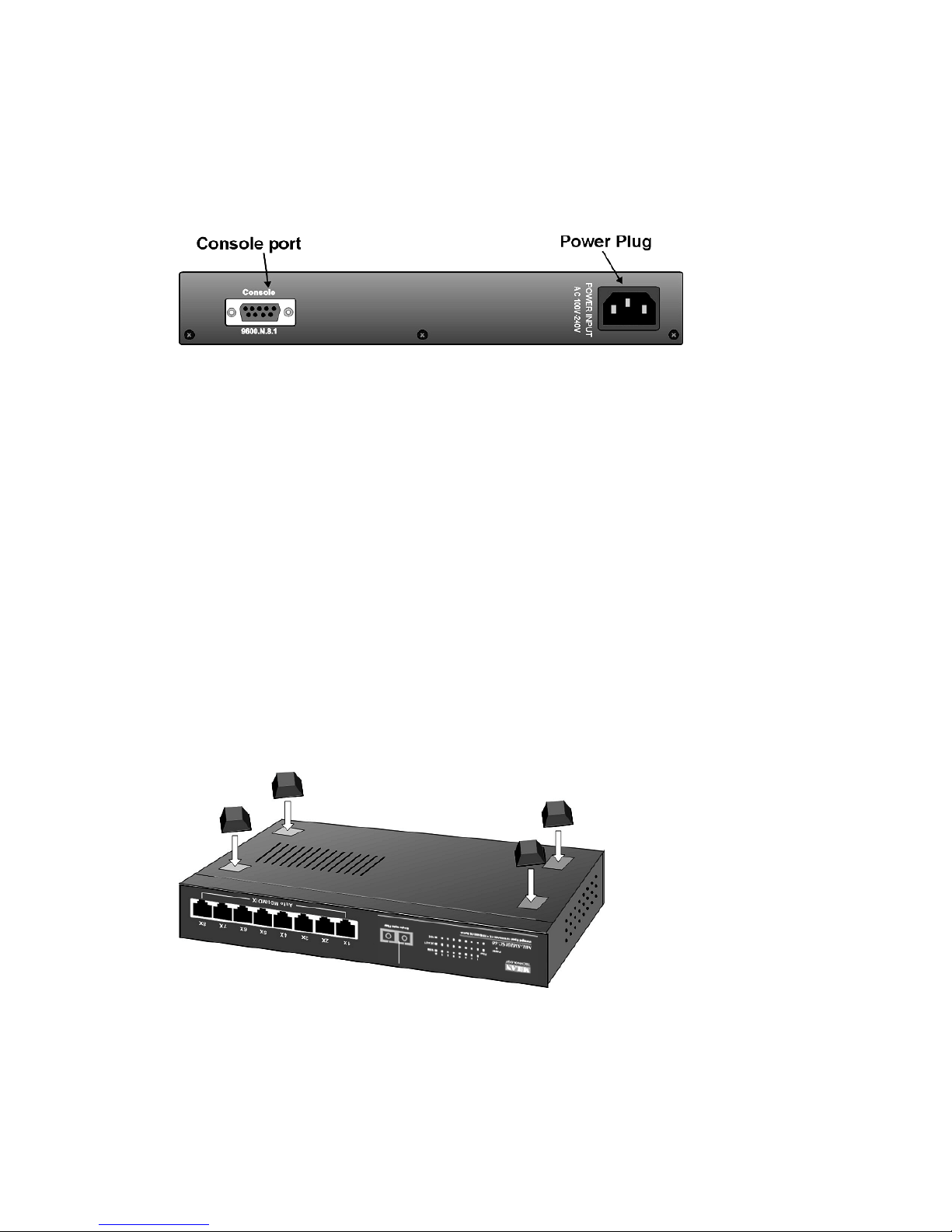
Rear Panel
The 3-pronged power plug is located at the rear panel of the switch as shown in
Figure 2-8. The switch will work with AC in the range of 100-240V AC, 50-60Hz.
Figure 2-8 The Rear Panel of the switch
Desktop Installation
Set the switch on a sufficiently large flat space with a power outlet nearby. The
surface should be clean, smooth, level, and sturdy. Make sure there is enough
clearance around the switch to allow for air circulation and the attachment of cables
and power cord.
Attaching Rubber Feet
A. Make sure mounting surface on the bottom of the switch is grease and dust
free.
B. Remove adhesive backing from the rubber feet.
C. Apply the rubber feet to each corner on the bottom of the switch. These
footpads can protect the switch from shock/vibration.
Figure 2-9. Attaching rubber feet to the bottom of the switch
8
 Loading...