

MiLAN MIL-FT240TX User Manual
User’s Guide
MIL-FT240TX
10/100 Fault-Tolerant Stand-Alone
Transceiver
• 10/100 Base-T(x) to 10/100 Base-T(x)
• Ethernet/Fast Ethernet
The MIL-FT240TX is a fault-tolerant
transceiver, providing redundant paths for fast Ethernet devices. It has three ports: main,
primary, and backup. Typically, the main port connects to a critical 10/100 fast Ethernet
device. The primary port and the backup port connect to two different switch ports or two
different ports on separate switches. When the unit powers up, it checks the primary port
for a link signal; if the signal is present, the main and primary ports will connect and the
signal from the backup port is disabled. Any device connected to the backup port will not
detect a signal at this time. However, if the device does not detect a signal on the primary
port, then the main port and backup port connect.
Product features . . . . . . . . . . . . . . . .2
Installation . . . . . . . . . . . . . . . . . . . .3
Operation . . . . . . . . . . . . . . . . . . . . .5
Cable Specifications . . . . . . . . . . . . .6
Troubleshooting . . . . . . . . . . . . . . . .7
Technical Specifications . . . . . . . . . .9
Contact Us . . . . . . . . . . . . . . . . . . .10
Compliance Information . . . . . . . . .11
*Typical maximum cable distance. Actual distance is dependent upon the physical
characteristics of th network.
Part Number Port One - Copper
10/100Base-T(x)
Port Two Copper
10/100Base-T(x)
Port Three - Copper
10/100Base-T(x)
MIL-FT240TX RJ-45 100 M
(328 ft*)
RJ-45 100 M
(328 ft*)
RJ-45 100 M
(328 ft*)
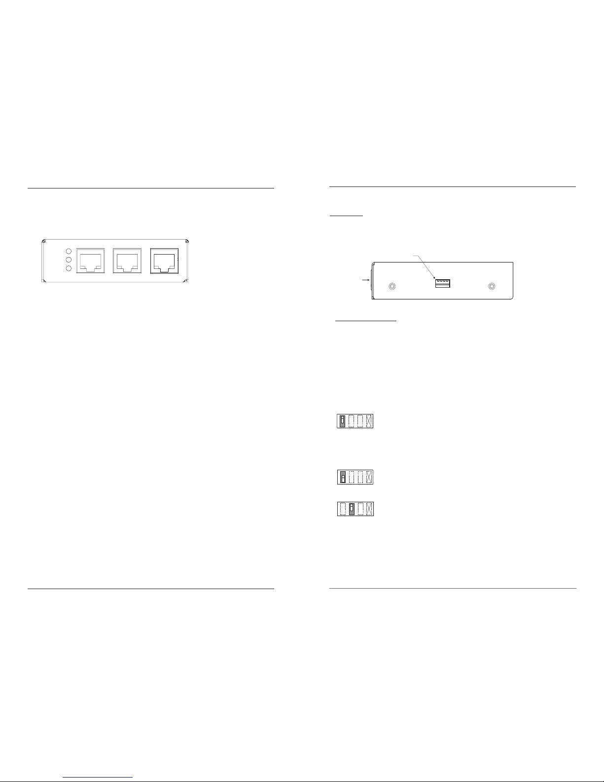
Product Features
Front panel
The MIL-FT240TX has three 10/100Base-T(x) ports.
Auto-Negotiation (selectable)
The Auto-Negotiation feature automatically configures the transceiver to achieve
the best possible mode of operation over a link. The transceiver broadcasts its speed
(10 Mb/s or 100 Mb/s) and duplex capabilities (full or half) to the other devices and
negotiates the best mode of operation. Auto-Negotiation allows quick and easy
installation because the optimal link is established automatically—no user
intervention required.
In a scenario where the media converter is linked to a non-negotiating device, the
user may want to disable Auto-Negotiation. In this instance, the mode of operation
will drop to the least common denominator between the two devices (e.g., 10 Mbs,
half-duplex). Disabling this feature gives the user the ability to force the connection
to the desired speed and duplex mode.
Data Transfer rate (selectable)
10Base-T data transfer rate: 10 Mbps baseband Ethernet
100Base-TX data transfer rate: 100 Mbps baseband Ethernet
Full-Duplex network (selectable)
In a full-duplex network, maximum cable lengths are determined by the type of
cables used. The 512-Bit Rule does not apply in a full-duplex network.
Half-Duplex network (selectable) (512-Bit Rule)
In a half-duplex network, the maximum cable lengths are determined by the round
trip delay limitations of each fast Ethernet collision domain. (A collision domain is
the longest path between any two terminal devices, e.g., terminal, switch, or router.)
The 512-Bit Rule determines the maximum length of cable permitted by calculating
the round-trip delay in bit times (BT) of a particular collision domain. If the result is
less than or equal to 512 BT, the path is good.
AutoCross™
When the AutoCross feature is activated, it allows either straight-through MDI or
crossover MDI-X cables to be used when connecting to 10Base-T or 100Base-TX
devices. AutoCross determines the characteristics of the connection and
automatically configures the unit to link up, regardless if the cable configuration is
MDI or MDI-X. This feature is ON permanently.
2
PWR
Prima ry
Backup
Main Primary Backup
10/100Base-TX 10/100Base-TX 10/100Base-TX
MIL-FT240TX
Technical Support: 1.800.466.4526. Press "2" -- International: 1.408.744.2751
Installation
CAUTION: Do Not install the MIL-FT240TX transceiver in location where it might be
exposed to wetness. Failure to observe this caution could result in damage to the
transceiver.
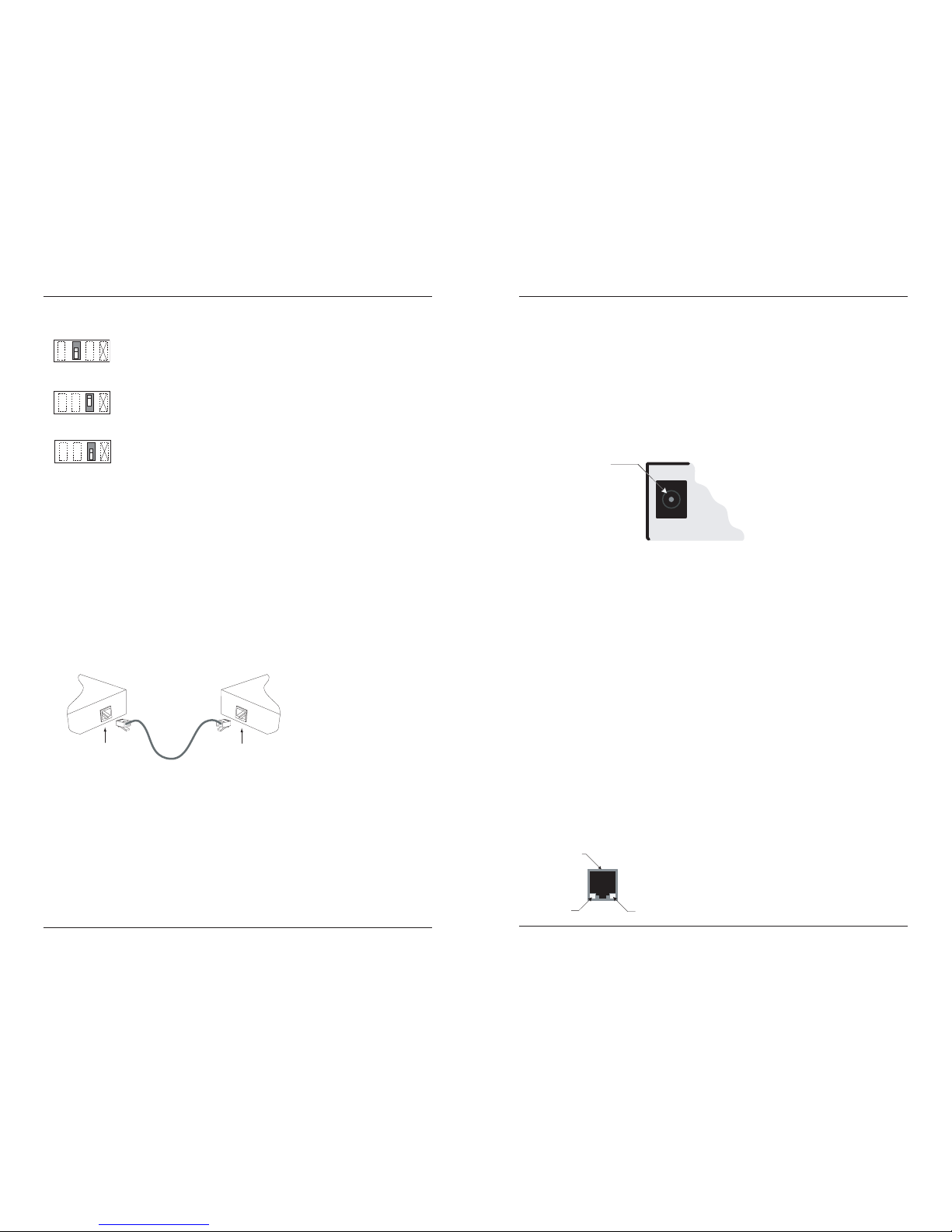
Set DIP Switch
Four (4) Dip Switches
• SW 1: Auto-Negotiation
• SW 2: Speed
• SW 3: Duplex
• SW 4: Not Used
Note: See the diagrams below and use a very small flatblade screwdriver or similar
device to set the DIP switch.
When Auto-Negotiation is enabled (switch #1 UP), the transceiver
advertises all rate and mode capabilities to the network: 100Mb/s full
duplex, 100Mb/s half-duplex, 10Mb/s full duplex, and 10Mb/s half
duplex.
Note: Switches “#3” and “#4” are non-functional when switch “#1” is in the UP
position (Auto-Negotiation enabled).
When auto-negotiation is disabled (switch #1 DOWN), the transceiver
does not advertise rate and mode capabilities to the network.
100Base-TX data transfer rate (switch #2 UP): 100 Mbps fast
Ethernet.
1342
Up
1342
Down
1342
Up
3
MIL-FT240TX
Email: support@milan.com
Side V iew
RJ-45 P orts
4 DIP S witches
4
MIL-FT240TX
Technical Support: 1.800.466.4526. Press "2" -- International: 1.408.744.2751
Installation -- Continued
10Base-TX data transfer rate (switch #2 DOWN): 10 Mbps Ethernet.
Full duplex switch #3 UP.
Half duplex switch #3 DOWN.
Note: The functionality for each switch setting applies to all ports simultaneously.
1342
Down
1342
Up
1342
Down
Installing the twisted-pair copper cable (customer supplied)
1. Locate or build an IEEE 803.2 compliant 10Base-T or 100Base-TX cables, with
male RJ-45 connectors installed onto both ends.
2. Connect the RJ-45 connector at one end of the cable to the RJ-45 port on the
transceiver as shown below.
3. Connect the RJ-45 connector at the other end of the cable to the RJ-45 port on the
other device (switch, workstation, etc.) as shown below.
Note: The MDI (straight-through) cable or the MDI-X (crossover) cable connection is
configured automatically, according to network conditions.
RJ-45 Port
Transceiver
RJ-45 Port
Switch,Workstati on, etc.
5
MIL-FT240TX
Installation -- continued
Connecting power to the media converter
AC/DC:
1. Connect the barrel connector of the adapter to the power port of the transceiver
(located on the back of the transceiver shown below).
2. Connect the power adapter plug into AC power: if all the configuration switches
are in the UP position, the port LEDs will flicker during the initialization
process and then go OFF.
Note: The power-on LED will be lit (ON).
Operation
Status LEDs
There are three (3) LEDs on the converter chassis front panel and two (2) on each TP
port.
Chassis LEDs
Power (PWR): LED ON indicates connection to an external AC power source
Primary: ON when the primary port is in use
Backup: ON when the backup port is in use
TP port LEDs
LINK/ACT/SPD: Green (ON) for 100 Mbps and Link/Act; Flashing when
transmitting data; Orange for 10Mbps
Duplex (DPX): Green (ON) for full duplex; OFF for half duplex
Chassis Rear
Barrel-Connector
Power Receptacle
TP Port
Dupl ex (DPX)
Li nx/ Act/ SPD
Email: support@milan.com
 Loading...