

Page 1

Let's get started.
Page 2

Page 3

Content
Safety
In the box
What you’ll need
Get the app
Installation For Drywall
Installation For Other Wall Surfaces
Limited Warranty & Compliance
For installation videos visit mikucare.com/support
4
5
6
7
8
27
50
Page 4

Safety
STRANGULATION HAZARD — Children have STRANGLED in cords.
NEVER attempt to use cord without the protective covering. Check protective covering before each
use to ensure that the cord is not exposed to your child. Immediately discontinue use if protective
covering is damaged or broken. This device is designed for indoor use only. This device is designed
to be used behind a standard crib and against the wall only. Use only the AC power supply included
with your Miku. Adult assembly is required. Keep small parts away from children when assembling.
This product cannot replace adult supervision. Ensure your child’s health by checking on him/her
regularly. This product is not a toy. Do not allow children to play with it.
DISCLAIMER — Miku Baby Monitor was created to help parents track factors that affect their
baby’s sleep schedule and general wellbeing. It is not intended to cure, treat, or prevent any disease
or health condition, including, but not limited to, Sudden Infant Death Syndrome (SIDS).No baby
monitor can ever replace you as a caregiver, or substitute for asking your doctor for medical advice.
PELIGRO DE ESTRANGULAMIENTO — Niños se han ESTRANGULADO con el cordón.
NUNCA intente de usar el cordón sin cobertura de protección. Cheque la cobertura de protección
antes de cada uso para asegurarse que el cordón no esté expuesto a su hijo(a). Inmediatamente
pare el uso si la cobertura the protection está dañada o quebrada. Este aparato está diseñado para
uso de interior. Este aparato está diseñado para uso detrás de cuna estándar y contra la pared
solamente. Use solamente el fuente de alimentación de CA incluido con su Miku. Asamblea de
adulto es necesario. Mantenga partes pequenas lejos the ninos cuando esté armando. Este producto
no es reemplazo the supervision de adulto. Asegure la salud de su hijo(a) por chequeando en el o
ella regularmente. Este producto no es un juguete. No permita que su hijo(a) juegue con el aparato.
DESCARGO DE RESPONSABILIDAD — Miku Baby Monitor fue creado para ayudar a los papás
rastrear factores que afecta el horario de sueño y el bienestar general de su hijo(a). El intento no es
the curar, tratar, o prevenir cualquier enfermedad o condición de salud, incluyendo, pero no limita
do a, el Síndrome de Muerte Súbita Infantil. Ningún monitor de bebé pueda reemplazar a usted de
un cuidador o cuidadora o ser un sustituto de conseguir consejo médico de su doctor.
-
QSGV007-EX
4
Page 5
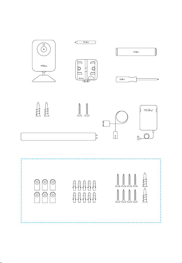
In the box
Pencil
THIS SIDE
Measuring Tape
UP
Baby Monitor
Large Drywall Anchors Screws
Cable Guides
Wall Mount
& Level
Optional Universal Hardware
Wall Guides
Universal Anchors
Screwdriver
Power Cord
Extra Screws &
Large Drywall Anchors
Power Supply
5
Page 6
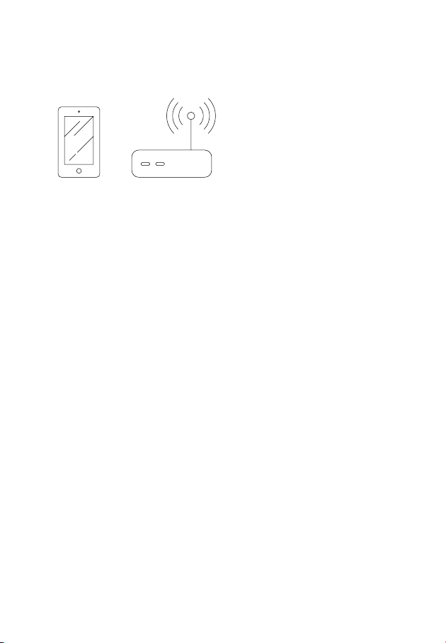
What you’ll need
Smart Device
WiFi Internet
QSGV007-EX
6
Page 7

Get the app
Now, get the app.
Download the free Miku app from mikucare.com/app and
create your user account.
Open the App and follow along to pair your Miku.
7
Page 8

Installation For Drywall
QSGV007-EX
8
8
Page 9
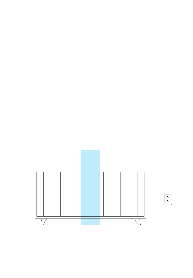
Installation For Drywall
1 |
Position the crib against the preferred wall in the nursery.
IMPORTANT: CRIB CENTER MUST BE IN A STUD-FREE AREA OF THE
WALL. If unsure, use a stud finder.
For wall surfaces other than drywall, please go to page 28 or view our
support page at mikucare.com/support
Stud-free
9
Page 10
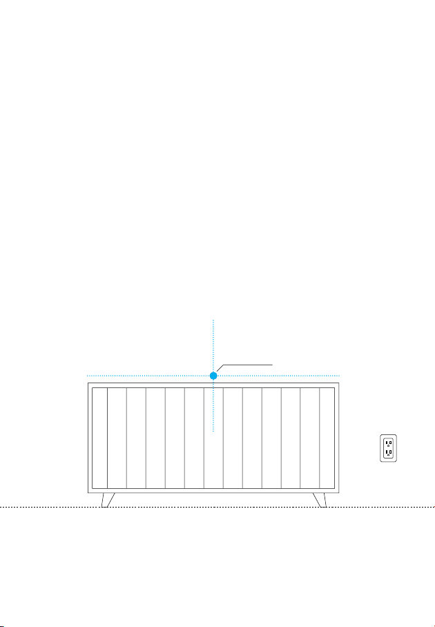
2 |
Using the Measuring Tape, find the center of the crib and
mark the wall with a pencil.
Note: Center of crib must be within 6 feet of an electrical outlet.
Then, move the crib away from the wall.
Crib Center
Installation For Drywall
10
QSGV007-EX
Page 11
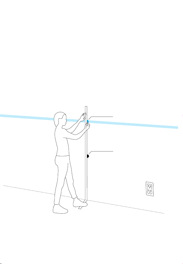
3 |
Step on the bottom of the Measuring Tape so it aligns with
the floor and your “Crib Center” mark on the wall. Lift the
tape up 60 inches and mark at the “MARK HERE” indicator.
Mark Here
60in
Crib Center
Installation For Drywall
11
Page 12

4 |
Take the Wall Mount and place it over your mark at 60 inches so you can see the mark through the center hole.
UP
THIS SIDE
Installation For Drywall
12
QSGV007-EX
Page 13
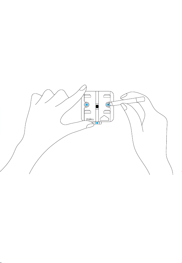
5 |
Use the Level below the Wall Mount to verify that it is level.
Mark the wall through the two holes in the Wall Mount.
UP
THIS SIDE
Installation For Drywall
13
Page 14

6 |
Pull and remove the Level from the bottom of the Wall
Mount.
Installation For Drywall
14
QSGV007-EX
Page 15

7 |
Using the Screwdriver, push and twist into the two marks
to create larger holes in the drywall. Only push as far as the
black tip of the Screwdriver.
Installation For Drywall
15
Page 16
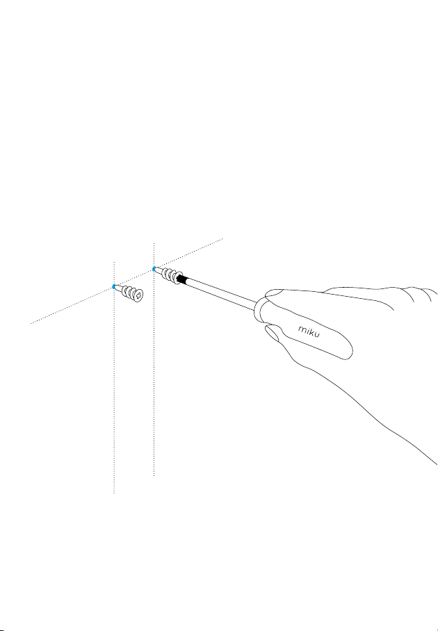
8 |
Push the Large Drywall Anchors into each hole and screw
them until they are flush.
Note: If the wall anchor doesn't screw into the wall easily, you may have hit
a stud. In this case no wall anchor is required for that hole.
Installation For Drywall
16
QSGV007-EX
Page 17
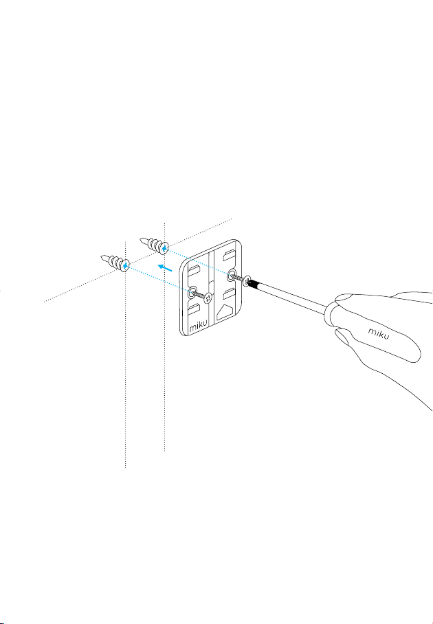
9 |
Position the Wall Mount over the “+” holes of the anchors.
Screw the Large Screws into the “+” holes and secure the
Wall Mount until flush with the wall.
UP
E
ID
IS S
TH
Note: Screw flush to the wall.
Do not overtighten.
Installation For Drywall
17
Page 18
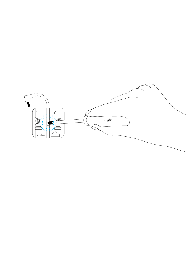
10 |
Unroll the Power Supply and align the top rubber indicator
to the center of the Wall Mount, leaving the top of the cord
hanging. Using the Screwdriver, push the rubber indicator
into the Wall Mount to secure the Power Supply.
UP
THIS SIDE
Installation For Drywall
18
QSGV007-EX
Page 19
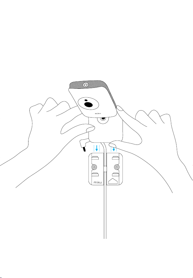
11 |
Slide the base of the Miku device into the Wall Mount until
it clicks.
UP
THIS SIDE
Installation For Drywall
19
Page 20
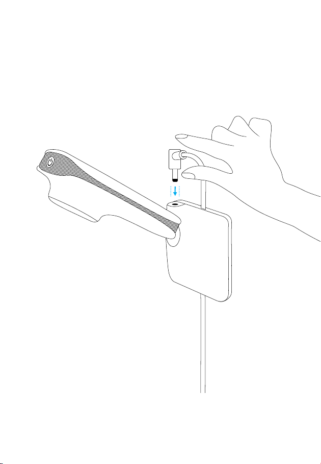
12 |
Plug the Power Supply into the back of the Miku device.
Installation For Drywall
20
QSGV007-EX
Page 21
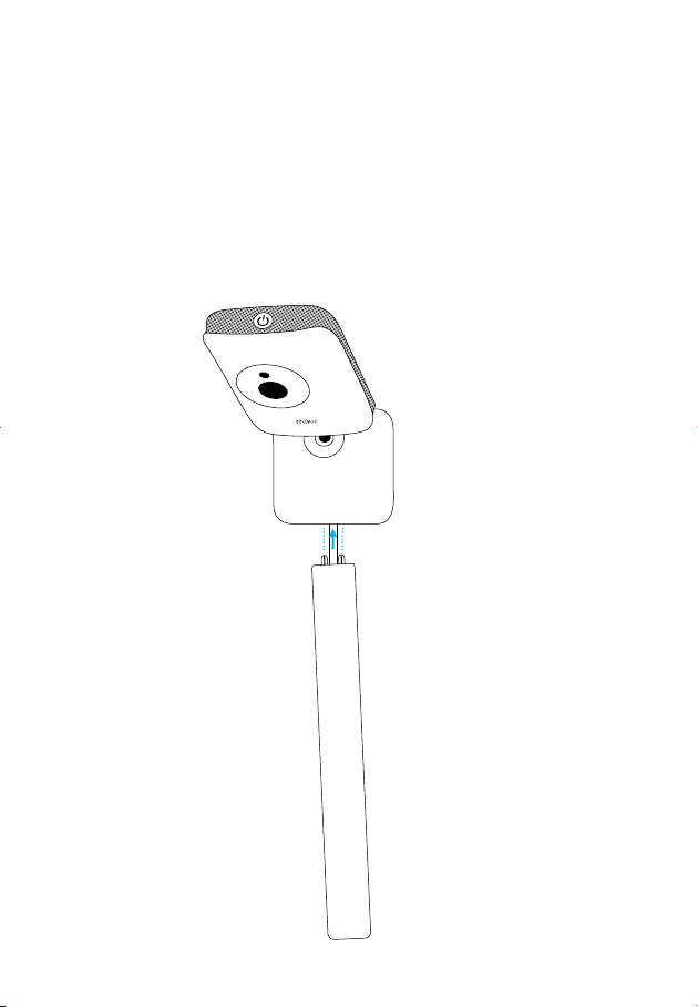
13 |
Insert the first Cable Guide into the bottom holes of the
Wall Mount, making sure the Cable Guide is covering the
cord.
Note: If you need to customize your cord path, you may need to use our
Optional Cable Guide Hardware.
Installation For Drywall
21
Page 22
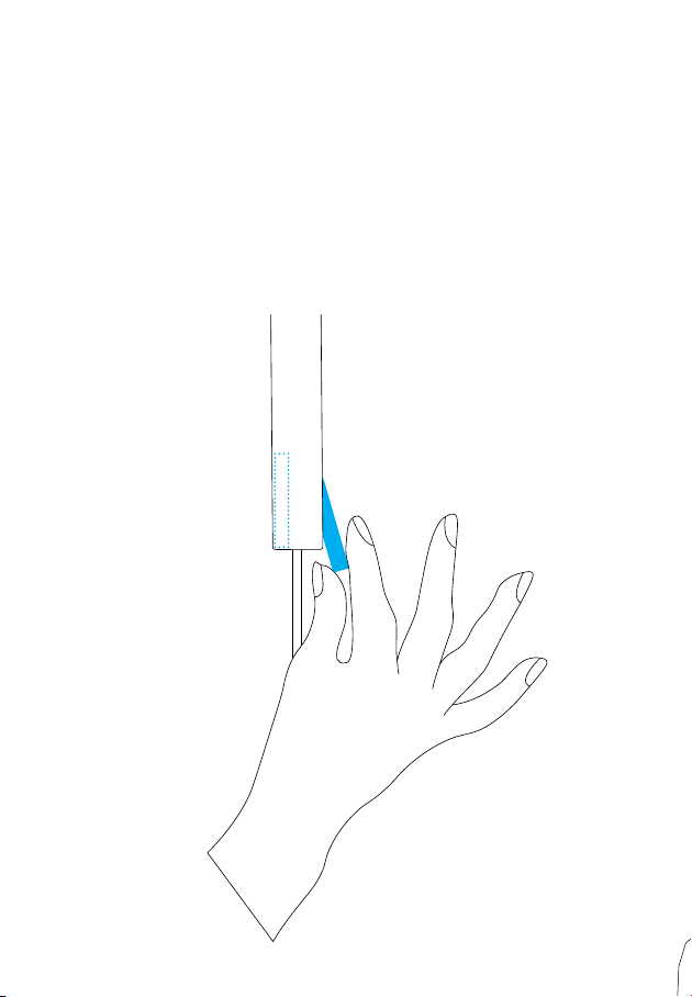
14 |
Remove the adhesive strips and adhere to wall.
Note: If you need to customize your cord path, you may need to use our
Optional Cable Guide Hardware.
Installation For Drywall
22
QSGV007-EX
Page 23
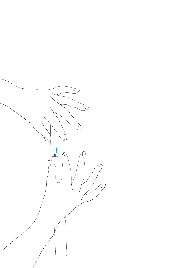
15 |
Insert each Cable Guide into the bottom holes of the previously installed section. Remove the adhesive strips and
adhere to the wall.
23
(a)
(b)
Installation For Drywall
23
Page 24
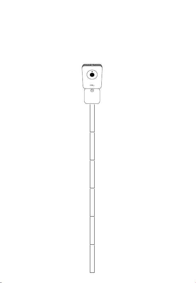
16 |
One by one, insert each Cable Guide into the bottom holes
of the previously installed section for all six sections. Remove
the adhesive strips and adhere to the wall.
1
2
3
4
Installation For Drywall
24
5
6
QSGV007-EX
Page 25
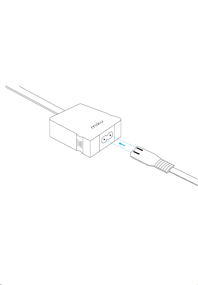
17 |
Connect the Power Cord to the Power Supply.
Installation For Drywall
25
Page 26
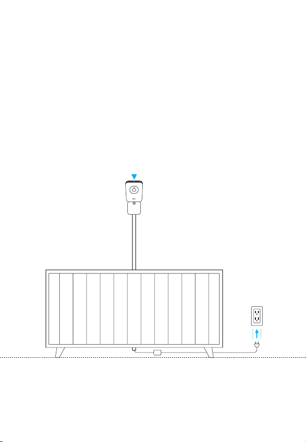
18 |
Plug the Power Cord into the nearest outlet. Once the power button light turns on, you're ready to go.
Installation For Drywall
26
QSGV007-EX
Page 27

Installation For Other Wall Surfaces
27
Page 28
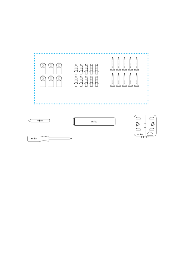
What you’ll need
Optional Universal Hardware
Wall Guides
Pencil
Screwdriver
Universal Anchors
Measuring Tape
Screws &
Drywall Anchors
Wall Mount
& Level
NOTE: For wall surfaces other than drywall you will need to use a drill and
our Optional Universal Hardware. Before you start make sure that your
wall can be drilled into and get the approprirate 1/4" drill bit for your wall
surface.
Installation For Other Wall Surfaces
28
UP
THIS SIDE
QSGV007-EX
Page 29
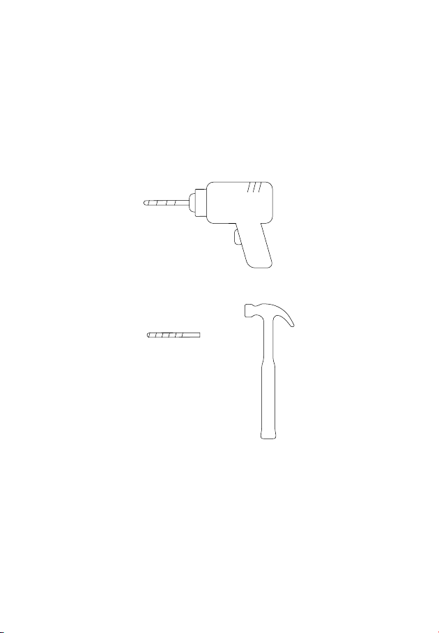
What you’ll need
Power Drill
1/4" Drill Bit
standard, masonary,
or wood spur depending
upon your wall surface.
Hammer
Installation For Other Wall Surfaces
29
Page 30
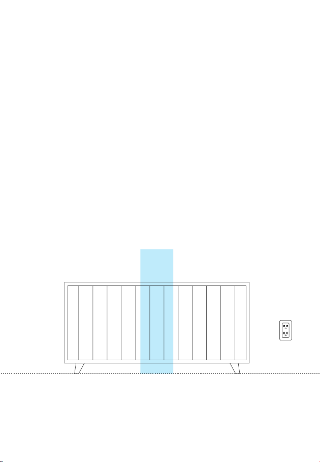
Installation For Other Wall Surfaces
1 |
Position the crib against the preferred wall in the nursery.
30
QSGV007-EX
Page 31
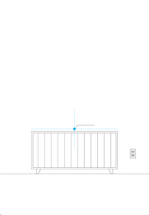
2 |
Using the Measuring Tape, find the center of the crib and
mark the wall with a pencil.
Note: Center of crib must be within 6 feet of an electrical outlet.
Then, move the crib away from the wall.
Crib Center
Installation For Other Wall Surfaces
31
Page 32
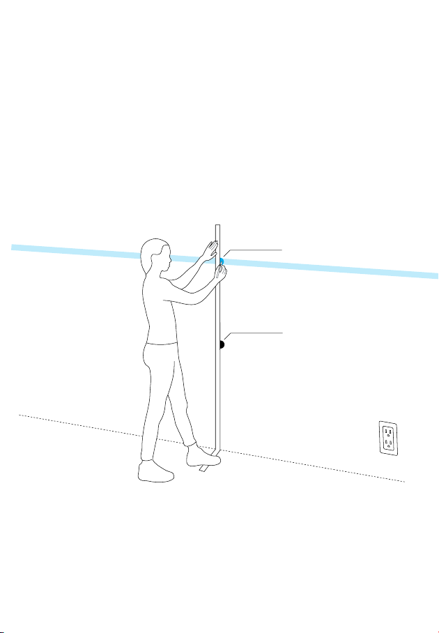
3 |
Step on the bottom of the Measuring Tape so it aligns with
the floor and your “Crib Center” mark on the wall. Lift the
tape up 60 inches and mark at the “MARK HERE” indicator.
Mark Here
60in
Crib Center
Installation For Other Wall Surfaces
32
QSGV007-EX
Page 33
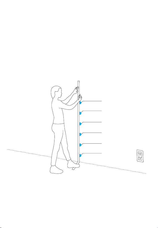
4 |
Put pencil marks at 55", 45", 35", 25", 15", and 5" in a
straight line. These will be for the Wall Guide clips.
55" Mark for Guide
45" Mark for Guide
35" Mark for Guide
25" Mark for Guide
15" Mark for Guide
05" Mark for Guide
Installation For Other Wall Surfaces
33
Page 34
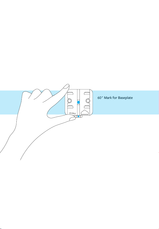
5 |
Take the Wall Mount and place it over your mark at 60 inches so you can see the mark through the center hole.
60" Mark for Baseplate
UP
THIS SIDE
Installation For Other Wall Surfaces
34
QSGV007-EX
Page 35
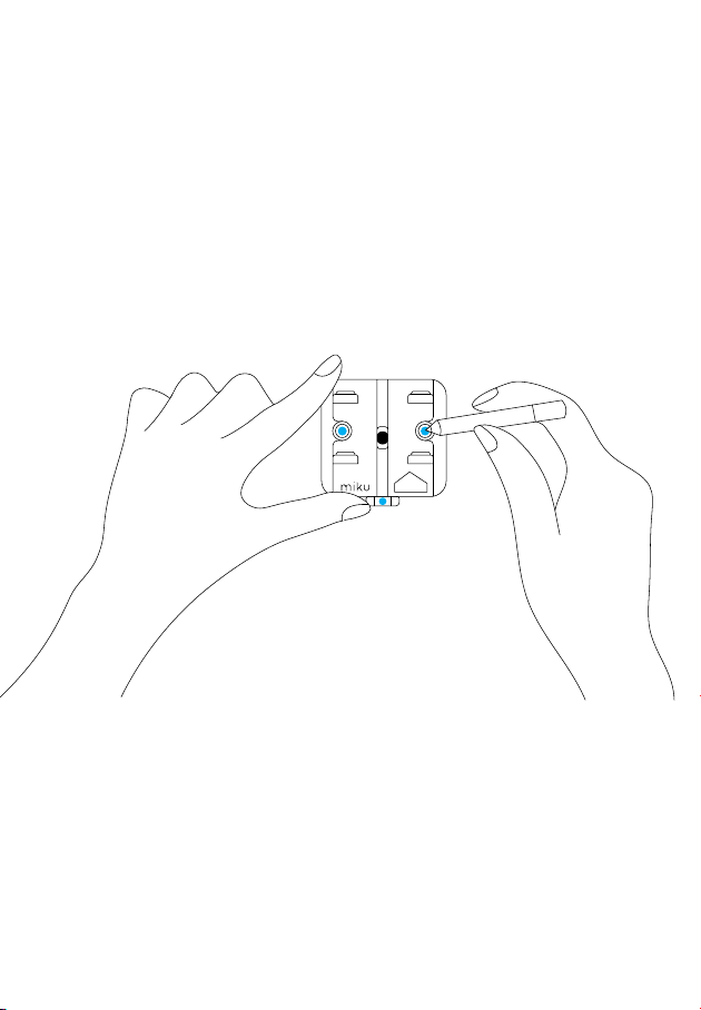
6 |
Use the Level below the Wall Mount to verify that it is level.
Mark the wall through the two holes in the Wall Mount.
UP
THIS SIDE
Installation For Other Wall Surfaces
35
Page 36
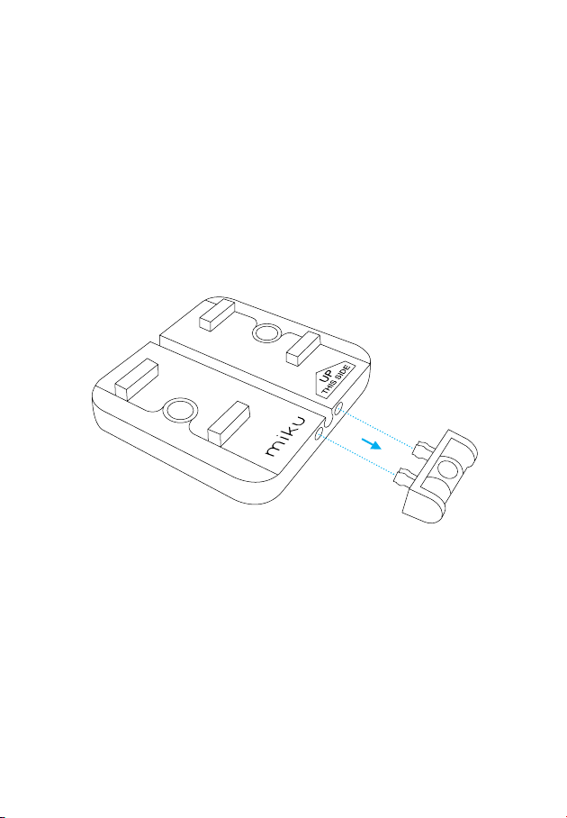
7 | Pull and remove the Level from the bottom of the Wall
Mount.
Installation For Other Wall Surfaces
36
QSGV007-EX
Page 37
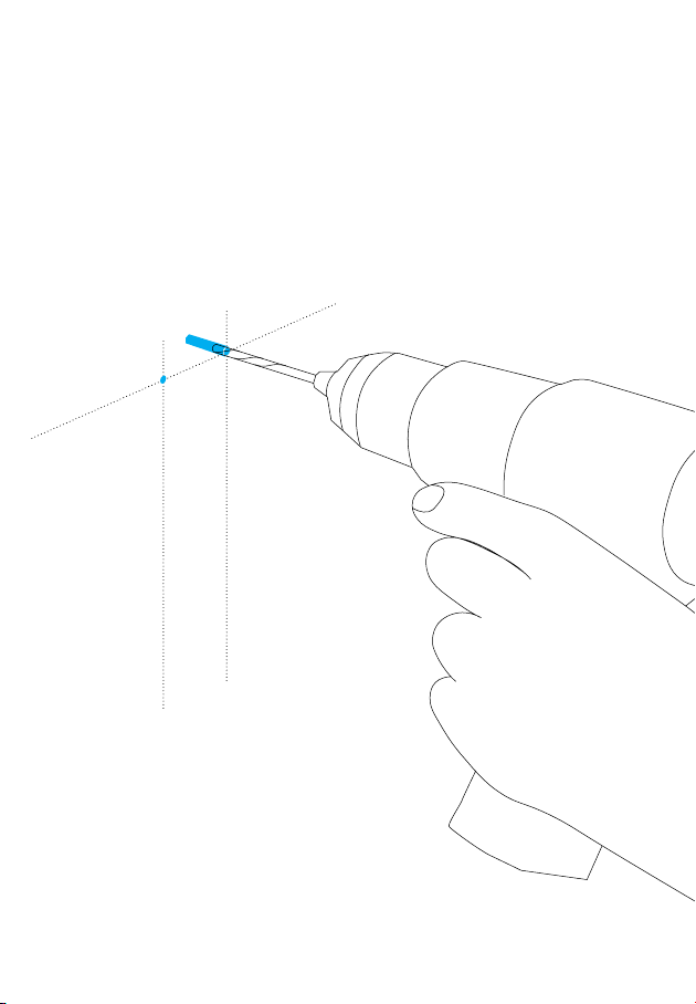
8 | First, confirm you have the correct 1/4" drill bit for the
wall surface type (standard, wood, or masonry). Drill a 1
1/2" hole in both marks.
1 1/2" depth
Installation For Other Wall Surfaces
37
Page 38
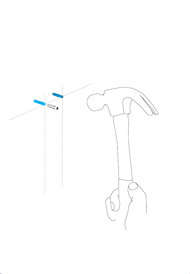
9 |
Place a universal anchor into each hole and tap flush into
the wall with a hammer.
Installation For Other Wall Surfaces
38
QSGV007-EX
Page 39
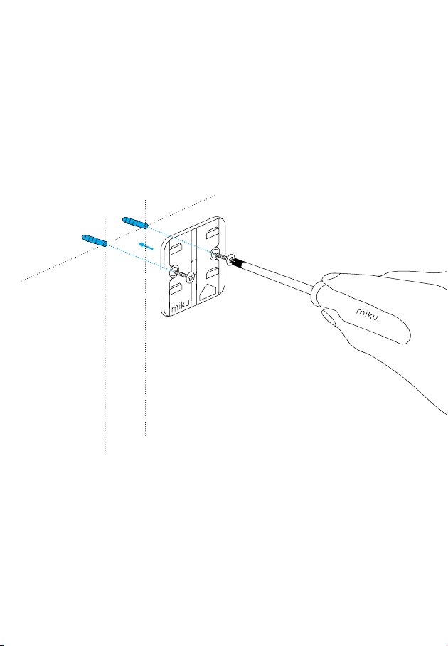
10 |
Position the Wall Mount over the holes of the universal
anchors and screw the Wall Mount until flush with the wall
surface.
UP
E
ID
IS S
TH
Note: Screw flush to the wall.
Do not overtighten.
Installation For Other Wall Surfaces
39
Page 40
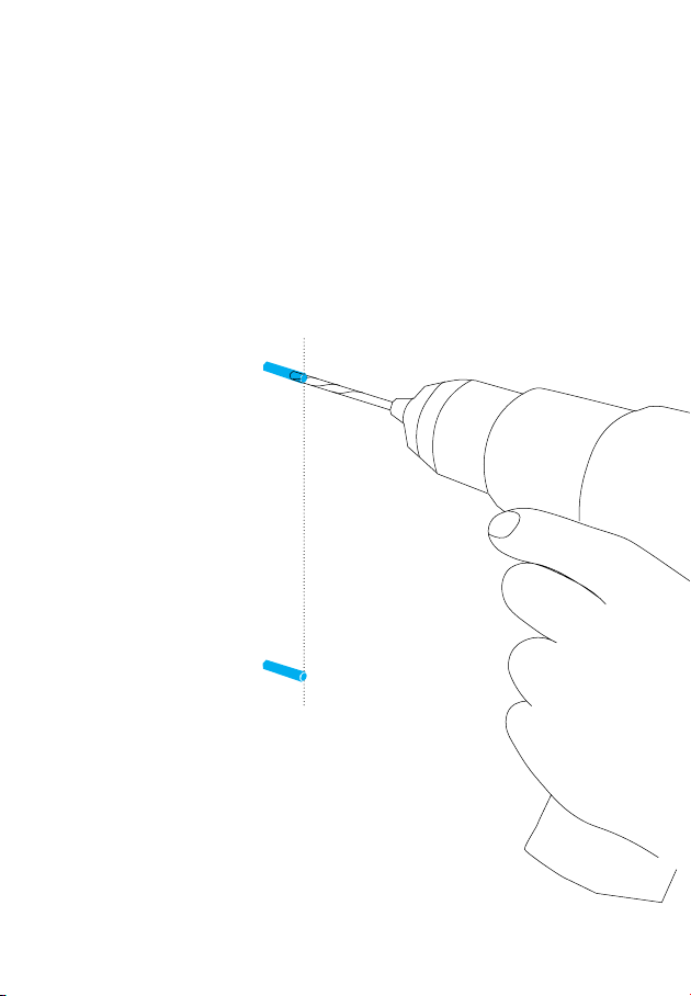
11 |
Drill a 1 1/2" hole for all of the Wall Guide Marks.
1 1/2" depth
55" Mark for Wall Guide
45" Mark for Wall Guide
Installation For Other Wall Surfaces
40
QSGV007-EX
Page 41
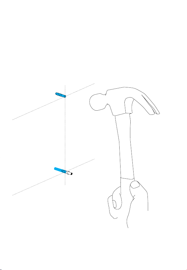
12 |
Place a universal anchor into each hole and tap gently with a
hammer until the anchor is flush with the wall.
Installation For Other Wall Surfaces
41
Page 42
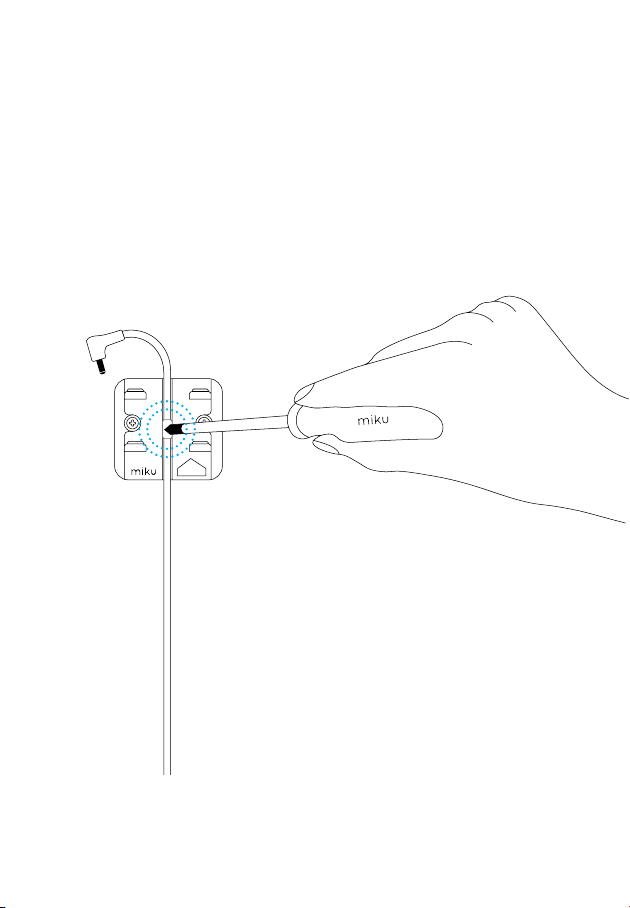
13 |
Unroll the Power Supply and align the top rubber indicator
to the center of the Wall Mount, leaving the top of the cord
hanging. Using the Screwdriver, push the rubber indicator
into the Wall Mount to secure the Power Supply.
UP
THIS SIDE
Installation For Other Wall Surfaces
42
QSGV007-EX
Page 43
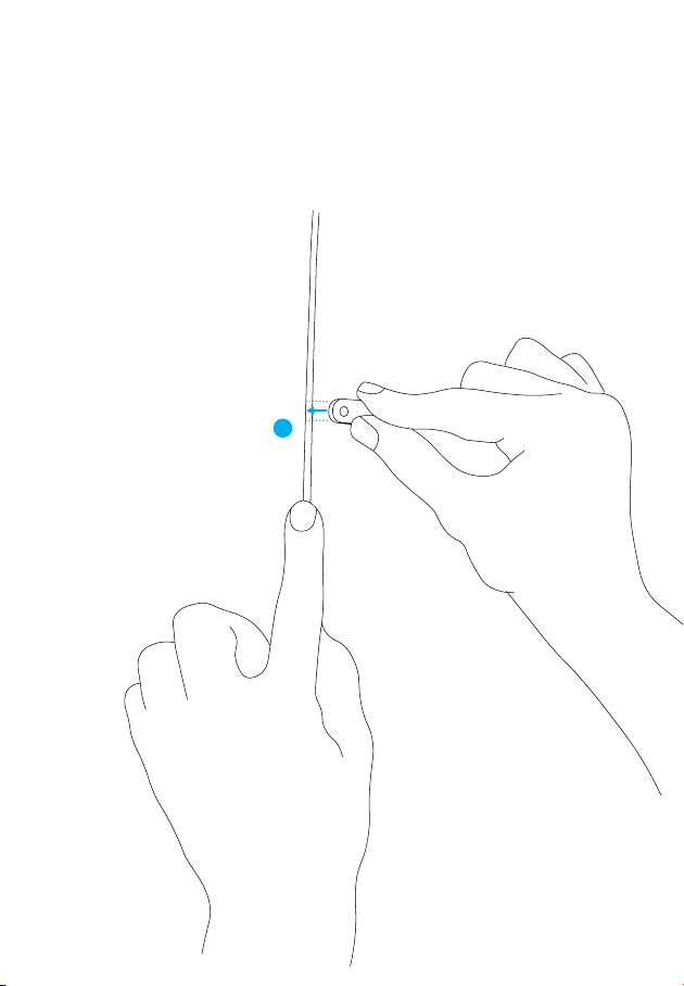
14 |
Clip a Wall Guide to the power cord near the 55" Universal
Anchor hole.
55" Universal Anchor
Installation For Other Wall Surfaces
43
Page 44
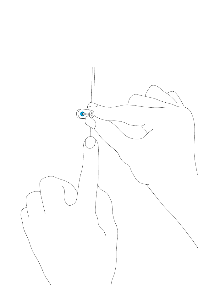
15 |
Align the Wall Guide to the Universal Anchor and place a
Screw in the hole. Now, repeat steps 12 & 13 until all of the
Wall Guides are in the wall.
55" Universal Anchor
Installation For Other Wall Surfaces
44
QSGV007-EX
Page 45
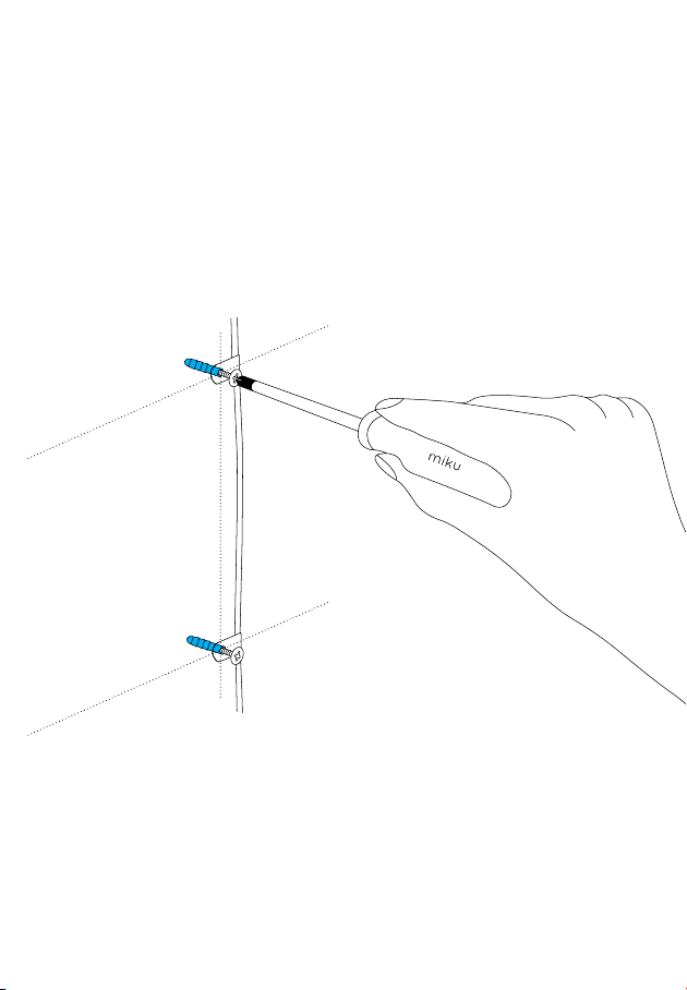
16 |
Use the Screwdriver to screw all of the Wall guides into
the wall.
Note: Screw flush to the wall.
Do not overtighten.
Installation For Other Wall Surfaces
45
Page 46
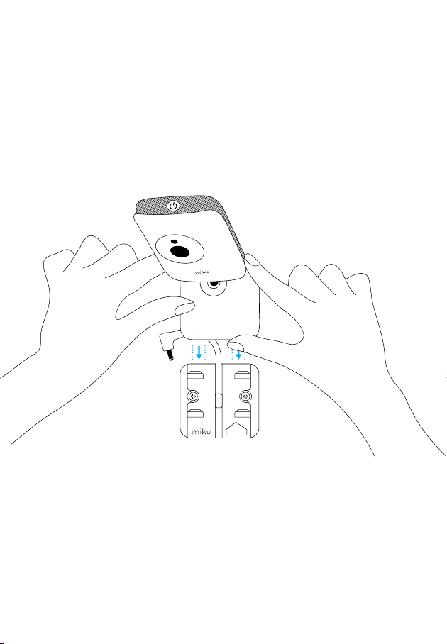
17 |
Slide the base of the Miku device into the Wall Mount until
it clicks.
UP
THIS SIDE
Installation For Other Wall Surfaces
46
QSGV007-EX
Page 47
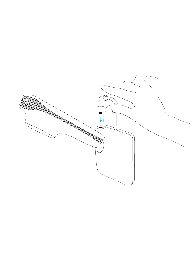
18 | Plug the Power Supply into the back of the Miku device.
Installation For Other Wall Surfaces
47
Page 48
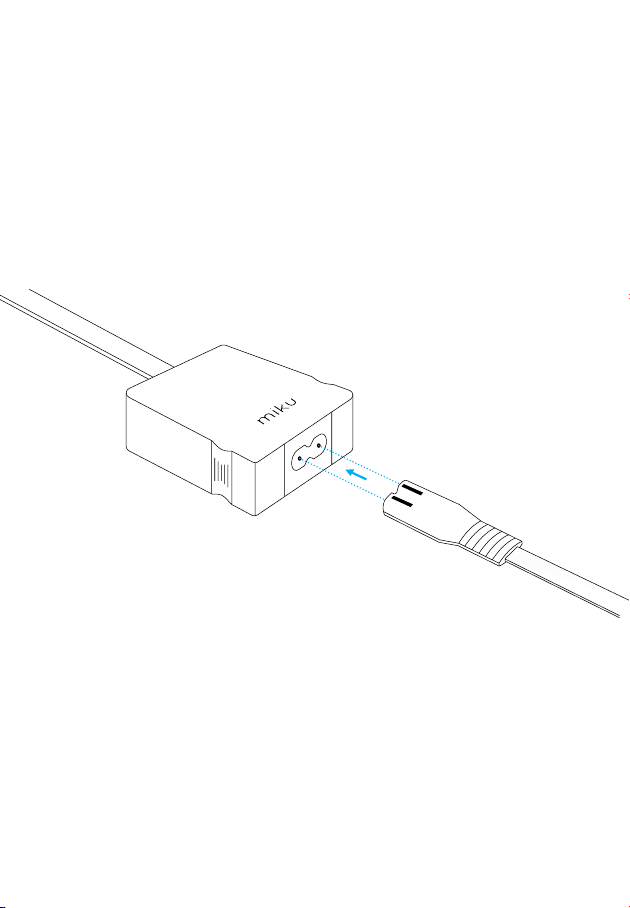
19 |
Connect the Power Cord to the Power Supply.
Installation For Other Wall Surfaces
48
QSGV007-EX
Page 49
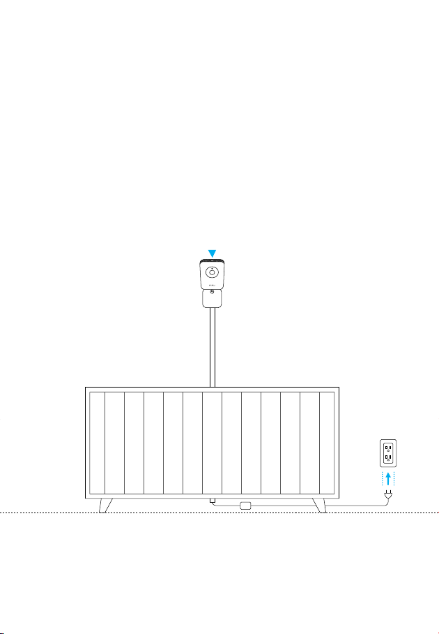
20 |
Plug the Power Cord into the nearest outlet. Once the power button light turns on, you're ready to go.
Installation For Other Wall Surfaces
49
Page 50
Limited Warranty & Compliance
For information on Miku's Limited Warranty visit:
mikucare.com/warranty
Miku, Inc. | Miku Life Monitor | Model No: M0100
FCC ID: 2AQM3M0100 | Contains TX FCC ID: 2AD9QX4M02
IC: 24123-M0100 | Contains TX IC ID: 22782-X4M02
CAN ICES-3(B)/NMB-3(B)
This device complies with Part 15 of the FCC Rules. Operation is subject to the following two
conditions:
(1) this device may not cause harmful interference, and
(2) this device must accept any interference received, including interference that may cause
undesired operation.
This equipment has been tested and found to comply with the limits for a Class B digital device,
pursuant to Part 15 of the FCC Rules. These limits are designed to provide reasonable protection
against harmful interference in a residential installation. This equipment generates, uses and can
radiate radio frequency energy and, if not installed and used in accordance with the instructions,
may cause harmful interference to radio communications.
However, there is no guarantee that interference will not occur in a particular installation. If
this equipment does cause harmful interference to radio or television reception, which can be
determined by turning the equipment off and on, the user is encouraged to try to correct the
interference by one or more of the following measures:
— Reorient or relocate the receiving antenna.
— Increase the separation between the equipment and receiver.
— Connect the equipment into an outlet on a circuit different from that to which the receiver is
connected.
— Consult the dealer or an experienced radio/TV technician for help.
50
QSGV007-EX
Page 51

CAUTION
Any changes or modifications not expressly approved by the grantee of this device could void the
user's authority to operate the equipment.
RF EXPOSURE WARNING:
The equipment complies with FCC RF exposure limits set forth for an uncontrolled environment.
The equipment must not be co-located or operating in conjunction with any other antenna or trans
mitter. This equipment should be installed and operated with minimum distance 20cm between the
radiator and your body. It could be removed.
CANADA, INDUSTRY CANADA (IC) NOTICES
This device complies with Canada licence-exempt RSS standard(s).
Operation is subject to the following two conditions: (1) this device may not cause interference,
and (2) this device must accept any interference, including interference that may cause undesired
operation of the device.
CANADA, AVIS D'INDUSTRY CANADA (IC)
Cet appareil est conforme avec Industrie Canada exemptes de licence RSS standard(s).
Son fonctionnement est soumis aux deux conditions suivantes : (1) cet appareil ne doit pas causer
d'interférence et (2) cet appareil doit accepter toute interférence, notamment les interférences qui
peuvent affecter son fonctionnement.
RADIO FREQUENCY (RF) EXPOSURE INFORMATION
The radiated output power of the Wireless Device is below the Industry Canada (IC) radio frequen
cy exposure limits. The Wireless Device should be used in such a manner such that the potential for
human contact during normal operation is minimized.
This device has also been evaluated and shown compliant with the IC RF Exposure limits under
mobile exposure conditions. (antennas are greater than 20cm from a person's body).
-
-
51
Page 52
INFORMATIONS CONCERNANT L'EXPOSITION AUX FRÉQUENCES RADIO (RF)
La puissance de sortie émise par l’appareil de sans fil est inférieure à la limite d'exposition aux
fréquences radio d'Industry Canada (IC). Utilisez l’appareil de sans fil de façon à minimiser les
contacts humains lors du fonctionnement normal.
Ce périphérique a également été évalué et démontré conforme aux limites d'exposition aux RF d'IC
dans des conditions d'exposition à des appareils mobiles (antennes sont supérieures à 20 cm à
partir du corps d'une personne).
RF EXPOSURE INFORMATION
This device meets the EU requirements (2014/53/EU) on the limitation of exposure of the general
public to electromagnetic fields by way of health protection.
CE MARK WARNING
This is a Class B product, in a domestic environment, this product may cause radio interference, in
which case the user may be required to take adequate measures.
POWER ADAPTER WARNING
The adapter shall be installed near the equipment and shall be easily accessible.
SIMPLIFIED EU DECLARATION OF CONFORMITY
Hereby, Miku, Inc., 10 Woodbridge Center Drive Suite 650, Woodbridge, NJ 07095 declares that the
radio equipment type Miku Life Monitor M0100 is in compliance with Directive 2014/53/EU. The full
text of the EU declaration of conformity is available at the following internet address: mikucare.
com/EU
AT BE DK GE EL
ES FI FR IE IT
NL PL SE UK
THE ABBREVIATIONS FOR MEMBER STATES SHALL BE AS FOLLOWS:
Belgium (BE), Bulgaria (BG), Czech Republic (CZ), Denmark (DK), Germany (DE), Estonia (EE),
Ireland (IE), Greece (EL), Spain (ES), France (FR), Croatia (HR), Italy (IT), Cyprus (CY), Latvia
(LV), Lithuania (LT), Luxembourg (LU), Hungary (HU), Malta (MT), Netherlands (NL), Austria
(AT),
Poland (PL), Portugal (PT), Romania (RO), Slovenia (SI), Slovakia (SK), Finland (FI), Sweden
(SE) and United Kingdom (UK).
This device meets the EU requirements (2014/53/EU) on the limitation of exposure of the general
public to electromagnetic fields by way of health
protection. This equipment should be installed and operated with minimum distance 20 cm
between the radiator and your body .
52
QSGV007-EX
Page 53

Page 54

54
QSGV007-EX
 Loading...