

Remarks, Notes and Warnings 4CXP Camera
EoSens 4CXP
Reference Guide
page 1 of 70 MIKROTRON GmbH

4CXP Camera Remarks, Notes and Warnings
Table of Content
About This Reference Guide ............................................................................................. 6
Remarks, Notes and Warnings ............................................................................................................ 6
Registered Trademarks ....................................................................................................................... 6
Conformity and Use .......................................................................................................... 7
Supplements ....................................................................................................................................... 8
Declaration of Conformity .................................................................................................................. 9
Warranty and Non-Warranty Clause ................................................................................................ 10
Scope of Delivery .............................................................................................................................. 11
System Requirements ....................................................................................................................... 12
Introduction ................................................................................................................... 13
Most Important Features .................................................................................................................. 13
Hardware ....................................................................................................................... 14
Rear Side of the Camera with DIN Connector .................................................................................. 14
Rear Side of the Camera with 5W5 Connector ................................................................................. 15
Connecting a Frame Grabber ............................................................................................................ 16
DIN Connector ............................................................................................................................... 16
5W5 Connector ............................................................................................................................. 17
Connecting an External Power Supply .............................................................................................. 18
12 Pin Hirose Connector and I/O Signals ...................................................................................... 18
6 Pin Hirose and I/O Signals .......................................................................................................... 19
Status LED ......................................................................................................................................... 20
Resolution and Speed ....................................................................................................................... 21
Cleaning the Sensor or the Lens ....................................................................................................... 21
First Steps ................................................................................................................... 22
Initial Setup ....................................................................................................................................... 22
Serial Number and Firmware ........................................................................................................ 22
Powering-up the Camera .............................................................................................................. 22
Configure Your 4CXP Camera .......................................................................................... 23
GenICam Standard ............................................................................................................................ 23
Camera Registers ............................................................................................................ 24
Bootstrap registers ............................................................................................................................ 25
Standard ........................................................................................................................................ 26
Revision ......................................................................................................................................... 27
page 2 of 70 MIKROTRON GmbH

Remarks, Notes and Warnings 4CXP Camera
XmlManifestSize ............................................................................................................................ 27
XmlManifestSelector ..................................................................................................................... 27
XmlVersion[XmlManifestSelector] ................................................................................................ 28
XmlSchemeVersion[XmlManifestSelector] ................................................................................... 28
XmlUrlAddress [XmlManifestSelector] ......................................................................................... 29
Iidc2Address .................................................................................................................................. 29
DeviceVendorName ...................................................................................................................... 30
DeviceModelName........................................................................................................................ 30
DeviceManufacturerInfo ............................................................................................................... 30
DeviceVersion ............................................................................................................................... 31
DeviceSerialNumber ..................................................................................................................... 31
DeviceUserID ................................................................................................................................. 31
Manufacturer-specific Addresses ..................................................................................................... 32
ConnectionReset ........................................................................................................................... 32
DeviceConnectionID ...................................................................................................................... 32
MasterHostConnectionID ............................................................................................................. 33
ControlPacketSizeMax .................................................................................................................. 33
StreamPacketSizeMax ................................................................................................................... 33
ConnectionConfig .......................................................................................................................... 34
ConnectionConfigDefault .............................................................................................................. 34
TestMode ...................................................................................................................................... 34
TestErrorCountSelector ................................................................................................................ 35
TestErrorCount[TestErrorCountSelector] ..................................................................................... 35
TestPacketCountTx[TestErrorCountSelector] ............................................................................... 35
TestPacketCountRx[TestErrorCountSelector] ............................................................................... 36
HsUpConnection ........................................................................................................................... 36
Acquisition Control ........................................................................................................................... 37
AcquisitionMode ........................................................................................................................... 37
AcquisitionStart ............................................................................................................................. 37
AcquisitionStop ............................................................................................................................. 38
AcquisitionBurstFrameCount ........................................................................................................ 38
TriggerSelector .............................................................................................................................. 38
TriggerMode [TriggerSelector] ...................................................................................................... 39
TriggerSource [TriggerSelector] .................................................................................................... 39
TriggerActivation [TriggerSelector] ............................................................................................... 40
TriggerSoftware ............................................................................................................................ 40
MIKROTRON GmbH page 3 of 70

4CXP Camera Remarks, Notes and Warnings
ExposureMode .............................................................................................................................. 41
ExposureTime ................................................................................................................................ 41
ExposureTimeMax......................................................................................................................... 41
AcquisitionFrameRate ................................................................................................................... 42
AcquisitionFrameRateMax ............................................................................................................ 42
TestImageSelector ........................................................................................................................ 43
Device Control ................................................................................................................................... 43
DeviceReset ................................................................................................................................... 43
Image Format Control ....................................................................................................................... 44
RegionSelector .............................................................................................................................. 44
RegionMode .................................................................................................................................. 45
RegionDestination ......................................................................................................................... 45
Width ............................................................................................................................................ 45
Height ............................................................................................................................................ 46
DecimationHorizontal ................................................................................................................... 46
DecimationVertical........................................................................................................................ 47
OffsetX .......................................................................................................................................... 47
OffsetY ........................................................................................................................................... 47
SensorWidth.................................................................................................................................. 48
SensorHeight ................................................................................................................................. 48
WidthMax ..................................................................................................................................... 48
HeightMax ..................................................................................................................................... 48
PixelFormat ................................................................................................................................... 49
TapGeometry ................................................................................................................................ 49
Image1StreamID ........................................................................................................................... 49
DeviceScanType ............................................................................................................................ 50
User Set Control ................................................................................................................................ 51
UserSetSelector ............................................................................................................................. 51
UserSetLoad[UserSetSelector] ...................................................................................................... 51
UserSetSave[UserSetSelector] ...................................................................................................... 52
UserSetDefaultSelector ................................................................................................................. 52
Analog Control .................................................................................................................................. 53
BlackLevel ...................................................................................................................................... 53
Gain ............................................................................................................................................... 53
Gamma Correction ........................................................................................................................ 53
Custom Features ............................................................................................................................... 54
page 4 of 70 MIKROTRON GmbH

Remarks, Notes and Warnings 4CXP Camera
TxLogicalConnectionReset ............................................................................................................ 54
PrstEnable ..................................................................................................................................... 55
PulseDrainEnable .......................................................................................................................... 55
DeviceInformationSelector ........................................................................................................... 55
DeviceInformation[DeviceInfoSelector] ....................................................................................... 56
FixedPatternNoiseReduction ........................................................................................................ 57
CustomSensorClkEnable ............................................................................................................... 57
CustomSensorClk .......................................................................................................................... 57
AnalogRegisterSetSelector ............................................................................................................ 58
AnalogRegisterSelector ................................................................................................................. 58
AnalogValue .................................................................................................................................. 58
InfoFieldFrameCounterEnable ...................................................................................................... 59
InfoFieldTimeStampEnable ........................................................................................................... 60
InfoFieldRoiEnable ........................................................................................................................ 61
Firmware and Update ................................................................................................. 62
Firmware Updater ............................................................................................................................. 62
Technical Data ................................................................................................................ 63
Sensor ............................................................................................................................................... 63
Camera .............................................................................................................................................. 63
Spectral Response .......................................................................................................... 64
MC4086 (monochrome) .................................................................................................................... 64
MC4087 (color) ................................................................................................................................. 65
Bayer Color Filter ............................................................................................................ 66
Bayer Pattern .................................................................................................................................... 66
Dimensions of MC4086/4087 .......................................................................................... 67
Rear View .......................................................................................................................................... 67
Side View ........................................................................................................................................... 67
Dimensions of MC4082/MC4083..................................................................................... 68
Rear View .......................................................................................................................................... 68
Side View ........................................................................................................................................... 68
Index .............................................................................................................................. 69
4CXP Camera Reference Guide V2.2 ............................................................................. 70
MIKROTRON GmbH page 5 of 70

Remarks, Notes and Warnings 4CXP Camera
Remark
Hints and other helpful information
Note
Hints concerning frame quality, timeouts, or other
WARNING
Important information concerning data loss or camera
damage
About This Reference Guide
This reference guide contains helpful information to install and operate 4CXP cameras of the type
MC4082/MC4083 and MC4086/ MC4087. It has been produced with care. Nevertheless, information
might be erroneous or incomplete. MIKROTRON cannot be held responsible for any problems
resulting from incomplete or erroneous information.
In case you detect errors or need further information, please inform us via mail: info@mikrotron.de
or call +49 89 7263420.
We highly recommend, reading this reference guide carefully.
This reference guide is subject to change without notice.
Remarks, Notes and Warnings
This reference guide contains remarks, notes and warnings that are helpful and often important in
order to avoid data loss or camera damage. They are emphasized as follows:
Registered Trademarks
In this reference guide the following products are registered trademarks:
CoaXPress®
EoSens®
GenICam®
In the following, these product names are not specially marked as registered trademarks.
Nevertheless, these product names have not to be used in other context without the trade mark
sign!
page 6 of 70 MIKROTRON GmbH

Registered Trademarks 4CXP Camera
Conformity and Use
This equipment has been tested and found to comply with the limits for a Class A digital device,
pursuant to Part 15 of the FCC Rules. These requirements are designed to provide reasonable
protection against harmful interference when the equipment is operated in a commercial
environment.
This equipment generates, uses, and can radiate radio frequency energy and, if not installed and
used in accordance with the instructions given in this reference guide, may cause harmful
interference to radio communications. Operation of this equipment in a residential area is likely to
cause harmful interference in which case the user will have to correct the interference at its own
expense.
Remark: You are herewith cautioned that any changes or modifications not expressly approved
in this reference guide could void your authority to operate this equipment.
制造说明:
此设备的生产与测试依照FCC条例第15条条例,符合A类电子设备标准。产品提供在商用使用环境
中的合理保护,以防止使用过程中可能涉及到的损害。
此设备会产生、使用并可发射出无线电波,如果未按照本手册中所述安装和使用,可能会对无线
通信设备产生干扰。如本设备在居民区操作出现干扰等情况,用户需要自费处理。
备注:请注意,如未按照此使用说明操作而自行更改设备,那么您将无权使用本设备。
規制適合宣言とご使用について (米国FCC)
この機器は、FCC規則のパート15に定められたクラスAデジタル装置に関する規制要件に
基づいて所定の試験が実施され、その適合が認証されています。 これらの規制要件は、商
業環境において機器を使用する際、有害な干渉に対する妥当な保護を提供するために設けら
れています。 この機器は、無線周波数エネルギーを生成かつ利用するとともに、放射する
こともあります。 このリファレンスガイドの指示に従って設置および使用が行われない場
合は、無線通信に有害な干渉を引き起こす恐れがあります。 この機器を住宅地で利用する
と有害な干渉を起こすこともあり、その場合、使用者は自己負担において適切な対策を講じ
る必要があります。
注意事項: このリファレンスガイドに明示的に承認していない変更や修正を行った場合
には、本製品を使用する権利が無効となることがあります。
page 7 of 70 MIKROTRON GmbH

4CXP Camera Supplements
Supplements
For customers in Canada
This apparatus complies with the Class A limits for radio noise emissions set out in Radio
Interference Regulations.
Pour les utilisateurs au Canada
Cet appareil est conforme aux normes Classe A pour bruits radioélectriques, spécifiées dans le
Règlement sur le brouillage radioélectrique.
Life Support Applications
The products described in this reference guide are not designed for use in life support appliances, or
devices and systems where malfunction of these products can reasonably be expected to result in
personal injury.
MIKROTRON customers using or selling these products for use in such applications do so at their
own risk and agree to fully indemnify MIKROTRON for any damages resulting from such improper
use or sale.
page 8 of 70 MIKROTRON GmbH

Declaration of Conformity 4CXP Camera
Title
EU Directive
RoHS Directive on the Restriction of the Use of Certain
Hazardous Substances in Electrical and Electronic Equipment
2011/65/EU
Approximation of the laws of the Member States relating to
electromagnetic compatibility and repealing Directive
89/336/EEC
2004/108/EC
Title
EU Standard
Information technology equipment - Immunity
characteristics - Limits and methods of measurement
EN 55024:1998 + A1:2001 + A2:2003
Information technology equipment - Radio disturbance
characteristics - Limits and methods of measurement
EN 55022:2006 + A1:2007
Declaration of Conformity
Manufacturer: MIKROTRON GmbH
Address: Landshuter Str. 20-22
D-85716 Unterschleissheim / Germany
Product: Cameras MC4082 / MC4083 and MC4086 / MC4087
We herewith declare under our sole responsibility that the dedicated products are in conformity
with the following EU directives:
During conformity-testing the following standards were consulted:
Unterschleissheim, May 06, 2015 Dipl. Kfm. Christian Pilzer (CEO)
MIKROTRON GmbH page 9 of 70
4CXP Camera Warranty and Non-Warranty Clause
WARNING
The camera does not contain serviceable parts. Do not
open the body of the camera. If the camera has been
opened, the warranty will be void.
The camera may only be used with a supply voltage
according to the camera specification. Connecting a
lower or higher supply voltage, AC voltage, reversal
polarity or using wrong pins of the power connector
may damage the camera. Doing so will void warranty.
Our warranty does not protect against accidental
damage, loss, or acts of nature.
MIKROTRON cannot be held responsible for the loss of
data. We recommend a backup plan.
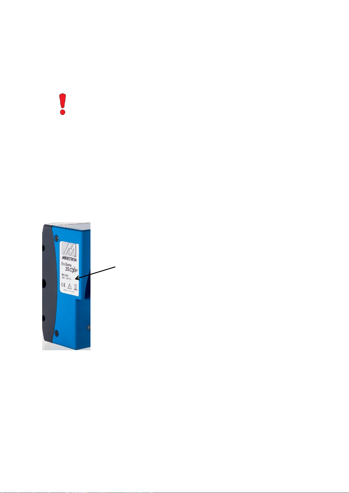
In case of warranty, please, make a
note of the camera type and serial
number and send the camera back
to your distributor. If no distributor
is available, send it back to
MIKROTRON.
You find all necessary information
on the identification plate of the
camera.
Warranty and Non-Warranty Clause
Warranty is described in §8 of our General Terms and Conditions which can be downloaded on
MIKROTRONS’ webpage: www.mikrotron.de
In addition, take the following non-warranty clauses into account:
Before sending back the camera, ask for a RMA number and form either by:
phone: +49 - 89 - 7263 4250 or
e-mail: service@mikrotron.de
page 10 of 70 MIKROTRON GmbH
Scope of Delivery 4CXP Camera
Scope of Delivery
The following components are part of delivery. Please check whether the delivery is complete,
before you start to install the camera:
Camera MC408x
F-Mount or C-Mount lens adapter (as ordered)
MIKROTRON’s Support CD
Optional:
several lenses www.mikrotron.de/en
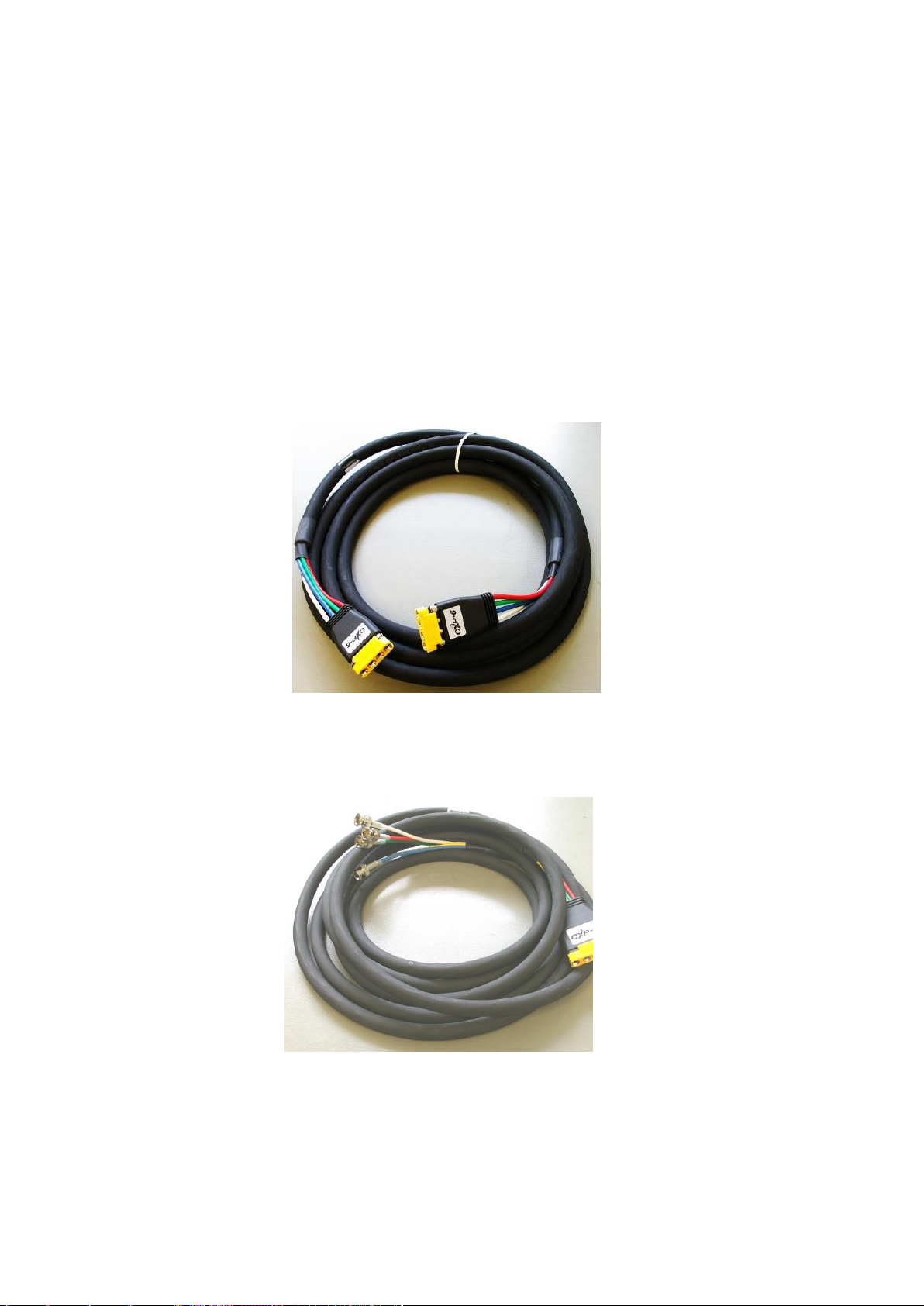
DIN 1.0/2.3: four bundle cable KKRDDINDINxx/6Gx4 with DIN 1.0/2.3 connector at
both ends (4x); available in lengths of 5, 10, 15 or 20 m
Remark: The triangle on the connector indicates connection 1.
DIN 1.0/2.3: cable KKRDDINBNCxx/6Gx4 with DIN 1.0/2.3 at one end and 4 BNC
connectors at the other; available in cable lengths of 5, 10, 15, 20 or 25m
page 11 of 70 MIKROTRON GmbH
4CXP Camera System Requirements
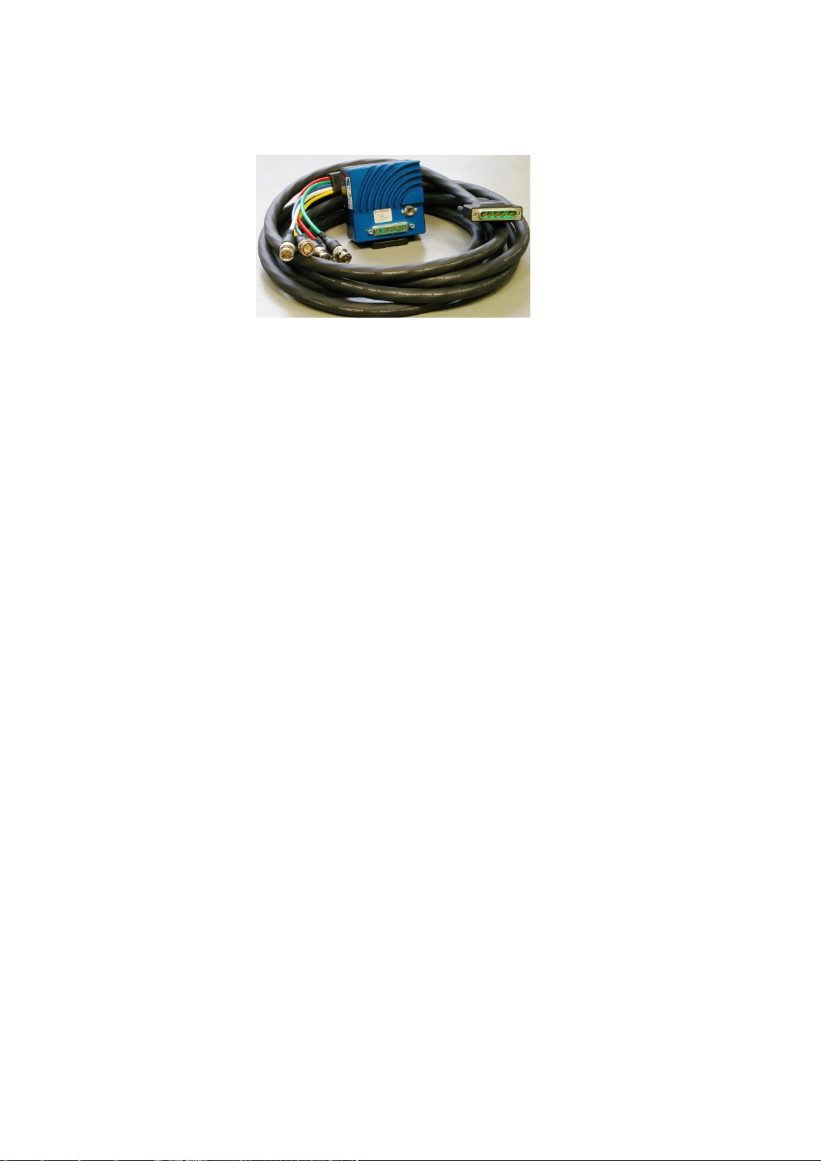
5W5: there are several cables (KKRD5W5BNCxx) for 6 GHz with a length of 5, 10, 15,
20 m or longer available. Please, contact your sales representative
external power supply unit:
MC3086/MC3087: NTCAM132x (12 V/2.5 A) with 12 pin Hirose connector
and 5 m cable
MC3082/MC3083: NTCAM13xx/NTCAM13XX10 with 6 pin Hirose connector
and 5/10 m cable
F-mount adapter
System Requirements
In order to use the MC408x camera you need:
image processing system, e.g.: PC and software
completely installed frame grabber (Device Driver, Software,...)
CoaXPress
if wanted, an external power supply (NTCAM132x or NTCAM13xx)
All cables, connectors and frame grabber have to be CoaXPress V1.1 compliant. Please, read the
application note AN0036 for more information on tested frame grabbers.
cable either with DIN 1.0/2.3 or 5W5 connector
page 12 of 70 MIKROTRON GmbH

Most Important Features 4CXP Camera
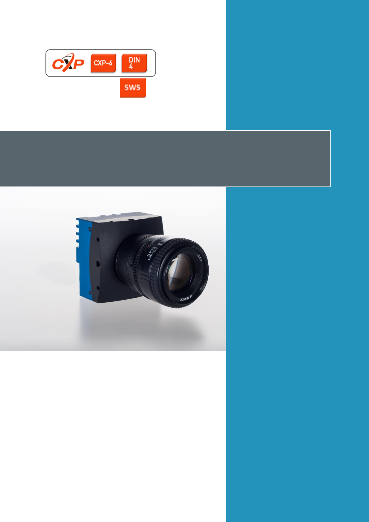
Introduction
All cameras of the EoSens 4CXP family are CoaXPress compliant. These high-speed CMOS cameras
come with a 4 Megapixel sensor of 2336 (H) x 1728 (V) and are widely configurable and scalable to
fit to your needs. They are available in monochrome and color (Bayer Filter).
The CoaXPress high speed interface technology allows transfer rates of up to 6.25 Gbps. Depending
on the camera model 4CXP cameras support CoaXPress Link Speeds from 1.25 Gbps to 6.25 Gbps.
In addition they offer a very high frame rate of over 500 fps at full resolution. By defining a Region of
Interest (ROI) the frame rate can be increased to several 1000ths of frames.
Another important feature of 4CXP cameras is the high photo sensitivity of 1600 ASA (monochrome)
or 1200 ASA (RGB).
Configuring the camera to Full HD resolution at 1920 x 1080 pixels using a frame rate of nearly
1000 fps opens a fascinating field of new applications. Full HD recordings are not only precious in
industrial or high-speed applications but also when shooting a scene in high resolution documentary
films or commercial clips.
The camera electronic is enclosed in a compact and solid full metal housing making it robust enough
to comply with the requirements in heavy industrial surroundings. Shielded coaxial cables as
recommended by the CoaXPress standard will support this.
4CXP cameras can be equipped with standard C-Mount or F-Mount lenses made for industrial
purpose.
Most Important Features
The most important features of the 4CXP camera family are:
small, compact housing ( page 67)
4 Megapixel high speed CMOS sensor
global shutter
monochrome or color (Bayer Filter)
CXP connection speed of 1.250, 2.500, 3.125, 5.000 or 6.250 Gbps
7 µm
resolution of 2336 x 1728 pixels
10/8 bit pixel output (256 gray levels)
4/3” optical format
up to 563 fps @ full resolution
sensitivity of up to 1600 ASA monochrome or 1200 ASA RGB
extended dynamic range of up to 60 dB
asynchronous trigger
trigger frequency of 150 (one edge) and 300 kHz in AnyEdge mode
arbitrary region of interest (ROI)
more than 17,236 frames/s with reduced resolution
communication and image transfer via CoaXPress
wide power supply range of 12 – 24V
2
pixels
and CXP6)
interface (CXP1, CXP2, CXP3, CXP5
MIKROTRON GmbH page 13 of 70
4CXP Camera Rear Side of the Camera with DIN Connector
Camera
Data width
[bit]
Mono: m
Color: c
Lens
adapter
Link speed
Max. frame-rate
@ 2336 x 1728
Connector Type
MC4082
8/10
m
C/F
CXP-6
563 fps
5W5
MC4083
8/10
c
C/F
CXP-6
563 fps
5W5
MC4086
8/10
m
C/F
CXP-5
566 fps
DIN1.0/2.3
MC4087
8/10
c
C/F
CXP-5
566 fps
DIN1.0/2.3
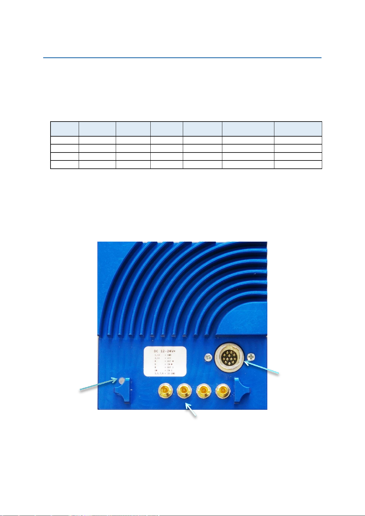
CoaXPress DIN 1.0/2.3 connector providing PoCXP
12 pin power
connector
LED
Hardware
4CXP cameras are available with 5W5 (MC-4082/4086) or DIN connector (MC-4083/4087). All are
equipped with the same sensor providing a resolution of 2336 x 1728 pixels. The color versions are
equipped with a Bayer color filter at the top of the sensor. This filter will code the color information
in the image pixels.
Table A: 4CXP camera features
Rear Side of the Camera with DIN Connector
At the rear of the cameras MC4086/4087 the DIN1.0/2.3 connector and the power connector are to
be found. The DIN connector with four lines is used to connect the camera with a CoaXPress frame
grabber and to supply the camera with power (power-over-coax, so called PoCXP).
Alternatively, a 12 pin Hirose power connector is available to connect an external power supply.
Remark: In order to connect an external trigger take the pinning of the Hirose connector on
page 17 into account and read the trigger settings starting on page 39.
page 14 of 70 MIKROTRON GmbH
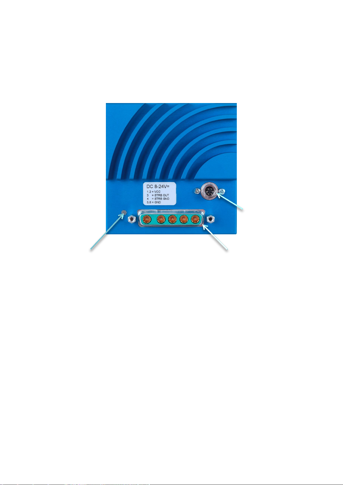
Rear Side of the Camera with 5W5 Connector 4CXP Camera
6-pin power
connector
5W5 connector
for CoaXPress
LED
Rear Side of the Camera with 5W5 Connector
At the back of the cameras MC4082/4083 the 5W5 connector and power connector are to be found.
The 5W5 connector is used to connect the camera via 4 lines with a CoaXPress frame grabber and to
supply the camera with power (power-over-coax, so called PoCXP).
Alternatively, a 6-pin Hirose power connector is available to connect an external power supply.
Remark: In order to connect an external trigger take the pinning of the Hirose connector on
page 19 into account and read the trigger settings starting on page 39
MIKROTRON GmbH page 15 of 70

4CXP Camera Connecting a Frame Grabber
CXP-Type
Transmission speed
Max. cable length
RG59 style
CXP-1
1.25 Gbit/s
up to 130 m
CXP-2
2.5 Gbit/s
up to 110 m
CXP-3
3.125 Gbit/s
up to 100 m
CXP-5
5 Gbit/s
up to 60 m
CXP-6
6.25 Gbit/s
up to 40 m
4x CXP-6
4*6.25 Gbit/s = 25 Gbit/s
up to 40 m
WARNING
Please, carefully connect and release the socket with
the DIN1.0/2.3 connector. Connect them precisely to
avoid deformation of the connectors or other
damages!
No. of
connections
Connector
combination
1 1 2
1+2 (link)
4
1+2+3+4 (link)
Connecting a Frame Grabber
At the time being, the CoaXPress standard describes 4 connections for data transmission between
camera and frame grabber. The transmission speed of a 4CXP camera can either be set to 1.25, 2.5,
3.125, 5 or 6.25 Gbit/s. The possible cable length depends on the cable type used and the
transmission speed. The following table gives examples. These values can only be reached if the
signal quality meets the requirements of the CXP-1.1 specification.
Table B: Maximal cable length depending on transmission speed
Remark: If several connections are used, all connections will have to be run with the same
transmission speed.
DIN Connector
In order to connect a MC4086/4087 camera with a frame grabber, use any compatible CoaXPress
cable with DIN connector. MIKROTRON offers cables with the following connectors ( page 11):
DIN<->DIN (KKRDDINDINxx/6Gx4)
DIN<->BNC (KKRDDINBNCxx/6Gx4)
If connecting a frame grabber via BNC, keep the order from left to right when making one, two, or
four connections. The inner left connector (1) is the master connector and always has to be
connected. All connections are hot-pluggable.
When using the DIN connector with a cable from MIKROTRON (e.g.: KKRDDINDINxx/6Gx4 ( page
11), use the pin with the triangle on the connector housing as pin 1.
page 16 of 70 MIKROTRON GmbH
Connecting a Frame Grabber 4CXP Camera
DIN Connector Pin
Cable Color
Function
1 (triangle)
blue
TX channel 0
2
white
TX channel 1
3
green
TX channel 2
4
red
TX channel 3
WARNING
Please, carefully connect and release the socket with
the 5W5 connector. Connect them precisely to avoid
deformation of the connectors or other damages!
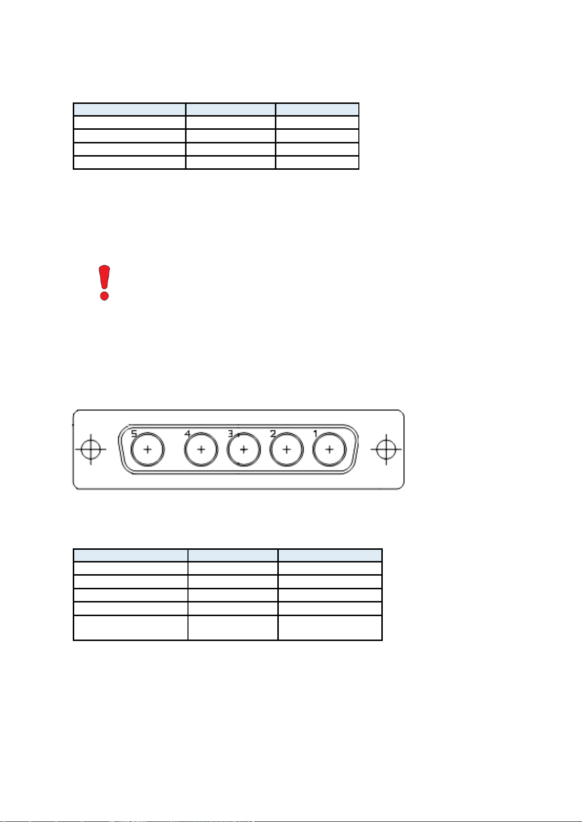
5W5 Connector Pin
Cable Color
Function
1
red
TX channel 0
2
green
TX channel 1
3
blue
TX channel 2
4
white
TX channel 3
5
yellow
TX channel 0 (not yet
assigned, do not use)
The assignment of the DIN-cables KKRDDINDINxx/6Gx4 and KKRDDINBNCxx/6Gx4 connector pins is
as follows:
5W5 Connector
In order to connect a MC4082/4083 camera with a frame grabber, use MIKROTRON’s cable
KKRD5W5BNC0x for 3 or 6 GHz and different lengths.
If connecting a frame grabber via BNC, keep the order from right to left. The outer right connector
(1) is the master connector and always has to be connected. All connections are hot-pluggable.
Connector 5 is not used.
Table 1: Assignment of the cable of the 5W5 connector
MIKROTRON GmbH page 17 of 70
4CXP Camera Connecting an External Power Supply
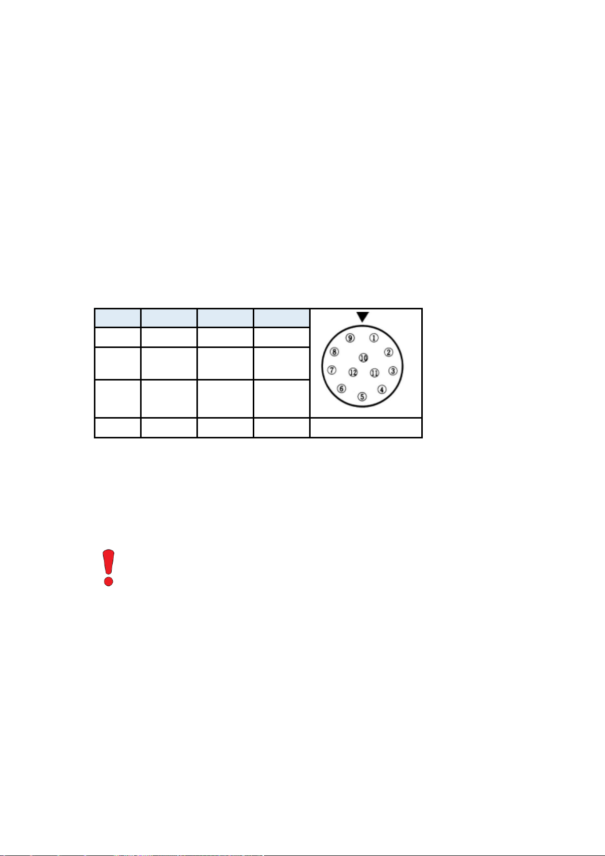
Pin
Signal
Pin
Signal
1 + 12
GND
5
TRIG
Line0 GND
2 + 11
VIN
(8 24 V)
6
TRIG
Line0 IN
3
STRB
GND
9
TRIG
Line1 GND
4
STRB
OUT
10
TRIG
Line1 IN
WARNING
The power connector of the camera has to be connected
with a DC power supply providing 12 to 24 V DC.
Connecting a lower or higher supply voltage, an AC
voltage, reversal polarity (+/-) or using wrong pins of the
power connector may damage the camera and will void
warranty.
Connecting an External Power Supply
All 4CXP cameras can either be supplied with power over coax (PoCXP) or via the Hirose connector
with an external power supply. MC4082/4083 cameras are equipped with a female 6-pin and
MC4086/4087 with a female 12 pin Hirose connector.
12 Pin Hirose Connector and I/O Signals
In case you prefer an external power supply for MC4086/4087, connect it with the 12 pin Hirose
connector (HR10A-10R-12PB (71)) at the back of the camera. The DC power supply has to deliver 12 24 V DC (7 W) ( page 11).
The 12 pin connector provides a strobe signal (STRB
) which is low during exposure and two inputs
OUT
for an external trigger ( page 39).
In case you assemble your own cable, pay attention to the pinning described below.
Table C: Pinning of the Hirose 12 pin power connector
Remarks:
The I/O pins 7 and 8 are not in use.
The I/O standard 3.3V LVTTL applies to all signal I/Os (STRB + TRIG).
page 18 of 70 MIKROTRON GmbH

Connecting an External Power Supply 4CXP Camera
Pin
Signal
Pin
Signal
1
VCC 6
GND
2
VCC 5
GND
3
STRB
OUT
(3.3 V LVTTL
I/O standard)
4
GND
STRB
WARNING
The power connector of the camera has to be connected
with a DC power supply providing 12 to 24 V DC.
Connecting a lower or higher supply voltage, an AC
voltage, reversal polarity (+/-) or using wrong pins of the
power connector may damage the camera and will void
warranty.
6 Pin Hirose and I/O Signals
The power connector of the cameras MC4082/MC4083 has to be connected via the 6-pin Hirose
connector (HR10A-7P-6S) with a DC supply voltage between 12 and 24 V at a power consumption of
7W max. The DC power supply unit is connected to a dedicated connector at the back side of the
camera. Please, take attention to the pin wiring of the connector as described below.
The 6 pin connector provides a strobe signal (STRB
) which is low during exposure.
OUT
In case you assemble your own cable, pay attention to the pinning described below.
Table 2: Pinning of the 6 pin power connector
MIKROTRON GmbH page 19 of 70

4CXP Camera Status LED
LED State
Indication
OFF
no power
solid orange
system is booting
slow pulse red
powered, but nothing connected
(not applicable to a device reliant on PoCXP power)
fast flash alternate green/orange
connection detection in progress, PoCXP active
fast flash orange
connection detection in progress, PoCXP not in use
slow flash alternate red/green
device incompatible, PoCXP active
slow flash alternate red/orange
device incompatible, PoCXP not in use
solid green
device connected but no data being transferred
slow pulse orange
device connected, waiting for event (e.g. trigger)
fast flash green
device connected, data being transferred
slow flash alternate green/orange
connection test packets being sent
red - 500 ms pulse
error during data transfer
slow flash alternate red/green/orange
compliance test mode enabled
fast flash red
system error
status LED
Status LED
A multi-color LED on the backplane of all 4CXP cameras indicate camera and CXP connection states
according to the CXP 1.1 standard.
Table D: LED indications
Remarks: If the LED signals the end of a successfully firmware update (green – slowly pulsating),
the camera can be switched off.
page 20 of 70 MIKROTRON GmbH

Resolution and Speed 4CXP Camera
WARNING
Never switch off the camera during a firmware update.
Otherwise the camera might be permanently damaged.
WARNING
Sensor Damage
Unplug the camera before you clean any parts!
In no case open the housing when cleaning the
window of the sensor.
If there are coarse particles on the lens or the window
of the sensor, use a vacuum cleaner to remove them
before cleaning in order to avoid scratches.
Use a dry, soft lens-cleaning tissue to clean the lens
and, if necessary, the window of the sensor.
Don't use tools that may harm the sensor/lens.
Resolution and Speed
There is a correlation between resolution and transmission speed for an 8 bpp image and 4
connections of 1.25, 2.5, 3.125, 5, or 6.25 Gbit/s.
Please use our camera compare tool under www.mikrotron.de/cameracompare in order to
determine the frame rate for a certain link speed and resolution.
Cleaning the Sensor or the Lens
If necessary, clean the window of the sensor and the lens with a dry, soft lens-cleansing tissue.
MIKROTRON GmbH page 21 of 70

4CXP Camera Initial Setup
First Steps
Before you start, make sure that all components of the camera/host chain like camera, connectors,
cable and frame grabber as well as the software are fully CoaXPress V1.1 compliant.
Procedure:
1. Switch off the image processing system
2. Connect the DIN V1.0/2.3 or 5W5 connector with the 4CXP camera
3. Connect the other end of the cable with your CoaXPress V1.1 compatible
frame grabber
4. If an external power supply is needed, connect the power supply
(12 - 24 V) via 12 pin Hirose connector with the camera
5. Unscrew the dust protection cover of the camera
6. Mount the lens
7. Switch-on the image processing system
8. As soon as the connection is established, connect the external camera
power supply with the main supply
Initial Setup
The MC408x comes with initial parameters and therefore does not have to be configured via the
host software. The initial settings include values like sensor resolution or frame rate.
Serial Number and Firmware
Serial number and firmware revision are provided in the non-volatile memory of the MC408x. Use
the according GenICam command to read the serial number and firmware revision ( Bootstrap
registers on page 25). The serial number is also to be found on the identification plate of the camera.
Powering-up the Camera
If the camera is powered-up, the power-up profile, which is permanently stored in the non-volatile
memory of the camera, will be loaded. This profile consists of a number of camera settings and is
used to bring the camera into a defined operation mode.
Remark: The camera has not to be configured by the host to start operation. The power-up
profile will deliver all necessary values like sensor resolution or frame rate, for
example.
page 22 of 70 MIKROTRON GmbH

GenICam Standard 4CXP Camera
Configure Your 4CXP Camera
4CXP cameras are based on the CoaXPress V1.1 specification. CoaXPress itself uses elements of the
GenICam standard to configure and control a camera. GenICam assumes that the camera uses a flat
register layout for configuration. Suppose, you want to change the exposure time, you have to write
the according value to the camera register representing the exposure time in hex values (e.g.
0x1100; page 37).
GenICam Standard
“The goal of GenICam is to provide a generic programming interface for all kinds of cameras. No
matter what interface technology the cameras are using or what features they are implementing, the
application programming interface (API) should be always the same.” ( GenICam Specification)
GenICam consist of three parts:
1. GenAPI
generic API (application programming interface) for cameras
2. SFNC
recommended names and features of compliant devices
3. GenTL
transport layer to be supported by any compliant frame grabber to transport camera data
into the application
With CoaXPress, the GenICam standard allows a direct connection between the software layer and
the camera. This means any CoaXPress camera and frame grabber can be used with this
standardized programming interface.
GenAPI allows the application software to communicate with the camera and read and write values
/ camera parameters. Every camera has therefore to be equipped with an "electronically readable
manual" to provide access and allow the GenAPI to:
read camera information and establish a connection to the frame grabber ( Bootstrap
registers on page 25)
control acquisition of images (Acquisition Control on page 37)
reset the camera (Device Control on page 43)
read or set the image format (Image Format on page 44)
select a user set ( User Set Control on page 51)
configure gain and blacklevel (Analog Control on page 53)
use custom features of the frame grabber ( Custom Features on page 54)
MIKROTRON GmbH page 23 of 70

4CXP Camera GenICam Standard
Notes
If not stated otherwise, all integer values will be interpreted as
32 bit unsigned integers.
All strings are NULL terminated and consist of 8 bit chars.
Camera Registers
All camera features are described and summarized in an "electronically readable manual" file. The
file is coded in ASCII using the Extensible Markup Language (XML) to describe each feature as a XML
feature knot.
Each feature knot consists at least of:
the feature type (command, string, integer...)
its access mode (r/w)
a descriptive name ('friendly name') of the feature
the corresponding register address
a short description of the feature in plain ASCII
There are also a number of additional elements that make a complete feature description. For
example the minimum and maximum values or its default value. Please, refer to the GenICam
documentation for further details.
The features in the XML file are grouped according to their meaning (e.g. Bootstrap registers, Image
format...).
The XML file can be saved (compressed or uncompressed) in the camera or as external file on your
local computer or a remote host. The file path (URL) can be read in 'XmlUrlAddress'.
page 24 of 70 MIKROTRON GmbH

Bootstrap registers 4CXP Camera
Name
Address
Access
Length
[Bytes]
Register
Interface
Page
Standard
0x00000000
R 4 Integer
26
Revision
0x00000004
R 4 Integer
27
XmlManifestSize
0x00000008
R 4 Integer
27
XmlManifestSelector
0x0000000C
R/W
4
Integer
27
XmlVersion
0x00000010
R 4 Integer
28
XmlSchemeVersion
0x00000014
R 4 Integer
28
XmlUrlAddress
0x00000018
R 4 Integer
29
Iidc2Address
0x0000001C
R 4 Integer
29
DeviceVendorName
0x00002000
R
32
String
30
DeviceModelName
0x00002020
R
32
String
30
DeviceManufacturerInfo
0x00002040
R
48
String
30
DeviceVersion
0x00002070
R
32
String
31
DeviceSerialNumber
0x000020B0
R
16
String
31
DeviceUserID
0x000020C0
R/W
16
String
31
WidthAddress
0x00003000
R/W
4
Integer
32
HeigthAddress
0x00003004
R/W
4
Integer
32
AcquisitionModeAddress
0x00003008
R/W
4
Integer
32
AcquistionStartAddress
0x0000300C
R/W
4
Integer
32
AcquistionStopAddress
0x00003010
R/W
4
Integer
32
PixelFormatAddress
0x00003014
R/W
4
Integer
32
DeviceTapGeometriyAddress
0x00003018
R/W
4
Integer
32
Bootstrap registers
CoaXPress compliant devices have to support a number of bootstrap registers as defined in this
chapter. In contrast to other CXP camera features each bootstrap register is assigned to a fixed
camera address which is defined in the CoaXPress specification.
Bootstrap registers are defined for device information and allow frame grabbers to establish and
maintain the connection between host and camera in a standardized way. The connection to the
camera is handled by the frame grabber in the background and is normally not in the scope of an
application developer. That is why registers for establishing and maintaining the grabber/camera
connection may not be of interest for most application programmer.
MIKROTRON GmbH page 25 of 70

4CXP Camera Bootstrap registers
Name
Address
Access
Length
[Bytes]
Register
Interface
Page
Image1StreamIDAddress
0x0000301C
R/W
4
Integer
32
ConnectionReset
0x00004000
W/(R)
4
Integer
32
DeviceConnectionID
0x00004004
R 4 Integer
32
MasterHostConnectionID
0x00004008
R/W
4
Integer
33
ControlPacketSizeMax
0x0000400C
R 4 Integer
33
StreamPacketSizeMax
0x00004010
R/W
4
Integer
33
ConnectionConfig
0x00004014
R/W
4
Enumerate
34
ConnectionConfigDefault
0x00004018
R 4 Integer
34
TestMode
0x0000401C
R/W
4
Integer
34
TestErrorCountSelector
0x00004020
R/W
4
Integer
35
TestErrorCount
0x00004024
R/W
4
Integer
35
TestPacketCountTx
0x00004028
R/W
8
Integer
35
TestPacketCountRx
0x00004030
R/W
8
Integer
36
HsUpConnection
0x0000403C
R 4 Integer
36
Start of manufacturer specific
register space
0x00006000
- - -
Access
read
Type:
unsigned integer
In: Out:
0xC0A79AE5
Remark:
The magic number is an approximation of CoaXPress.
Standard
This register provides a magic number (see OUT) indicating the device implements the CoaXPress
standard.
page 26 of 70 MIKROTRON GmbH

Bootstrap registers 4CXP Camera
Access
read
Type:
unsigned integer
In:
-
Out:
Bits
Description
31-16
major revision
15-00
minor revision
Remark:
Devices compliant to this revision 1.1 of the specification shall return 0x00010001.
Access
read
Type:
unsigned integer
In:
Out:
1 ... N
Access
read / write
Type:
unsigned integer
In:
0 … XmlManifestSize-1
Out:
0 … XmlManifestSize-1
Remark:
A connection reset sets the value to 0x00000000.
Revision
This register provides the revision of the CoaXPress specification implemented by this Device.
XmlManifestSize
This register returns the number of available XML manifests. At least one manifest must be available.
XmlManifestSelector
This register selects the required XML manifest registers.
It holds a number between zero and XmlManifestSize – 1.
MIKROTRON GmbH page 27 of 70

4CXP Camera Bootstrap registers
Access
read
Type:
unsigned integer
In:
Out:
Bits
Name
Description
31-24
reserved
shall be 0
23-16
SchemaMajorVersion
major version number of the XML file
15-8
SchemaMinorVersion
minor version number of the XML file
7-0
SchemaSubMinorVersion
sub-minor version number of the XML file
Access
read
Type:
unsigned integer
In:
Out:
Bits
Name
Description
31-24
reserved
shall be 0
23-16
SchemaMajorVersion
major version number of the schema used by the XML file
15-8
SchemaMinorVersion
minor version number of the schema used by the XML file
7-0
SchemaSubMinorVersion
sub-minor version number of the schema used by the XML file
XmlVersion[XmlManifestSelector]
This register provides the version number for the XML file given in the manifest referenced by
register XmlManifestSelector.
XmlSchemeVersion[XmlManifestSelector]
This register provides the GenICam schema version for the XML file given in the manifest referenced
by the register XmlManifestSelector.
page 28 of 70 MIKROTRON GmbH

Bootstrap registers 4CXP Camera
Access
read
Type:
unsigned integer
In: - Out:
register address
Remark:
Reading from the returned register address returns n characters representing the
name, the register address and the length of the GenICam XML file stored in the flash
memory of the camera. The format of the address string is:
Field
Description
Local
indicates the XML file is stored in non-volatile memory in the Device
<Filename>
name of the XML file; the file name has no meaning if the XML file is
stored in the camera
<Extension>
“xml” indicates an uncompressed text XML file
“zip” indicates a ZIP format compressed text file
<Address>
start address of the file in the device memory map, given in hexadecimal
form without a leading “0x”. The address string can be read from this
address
<Length>
length of the file in Bytes, given in hexadecimal without a leading “0x”
Example: “Local:Mikrotron_GmbH_MC408xS11_Rev1_15_0.xml;
8001000;16C34?SchemaVersion=1.1.0”
References a GenICam XML file in the flash memory of the camera.
The file can be read starting at address 0xB8000 and has a length of 0x33A Bytes.
The returned string could also reference a XML file located on the vendors homepage.
This location is not used by our cameras.
Access
read
Type:
unsigned integer
In:
Out:
0x00000000
Remark:
not supported
XmlUrlAddress [XmlManifestSelector]
This register indicates the start of the URL string referenced by register XmlManifestSelector.
Iidc2Address
Devices that support the IIDC2 protocol (section 2.2 ref. 6). This register shall provide the address of
the start of the IIDC2 register space.
MIKROTRON GmbH page 29 of 70

4CXP Camera Bootstrap registers
Access
read
Type:
string[0...32]
In:
Out:
vendor name
Remark:
Example: MIKROTRON GmbH
Access
read
Type:
string[0...32]
In: Out:
model name
Remark:
Example: MC2586
Access
read
Type:
string[0...48]
In:
Out:
manufacturer information
Remark:
Example: “MIKROTRON GmbH”
DeviceVendorName
This register provides the name of the manufacturer of the device as a string.
DeviceModelName
This register provides the model name of the Device as a string.
DeviceManufacturerInfo
This register provides extended manufacturer-specific information about the device as a string.
page 30 of 70 MIKROTRON GmbH

Bootstrap registers 4CXP Camera
Access
read
Type:
string[0...32]
In:
Out:
device version string
Remark:
Format of the version string (Byte numbers from left to right):
Byte
Description
Sample
0
hardware tag
“H”
1-3
hardware version major number
“000”
4
“.”
5-7
hardware version minor number
“001”
8
“.”
9-13
hardware version sub minor number
“00000”
The sample in the table above results in the device version string: H000.100.00000
Access
read
Type:
string[0...16]
In: Out:
serial number of the camera
Remark:
Example: 000000000000157
Access
read/write
Type:
string[0...16]
In:
user ID
Out:
user ID
Remark:
The User ID can be freely defined by the user.
It will be saved in the flash memory of the camera. As a result, it will be preserved if the
camera is switched off.
DeviceVersion
This register provides the version of the camera hardware as a string.
DeviceSerialNumber
This register provides the serial number for the device as a NULL-terminated string.
DeviceUserID
This register provides a user-programmable identifier for the camera as a string.
MIKROTRON GmbH page 31 of 70

4CXP Camera Manufacturer-specific Addresses
WidthAddress
manufacturer-specific address of Width
HeightAddress
manufacturer-specific address of Height
AcquisitionModeAddress
manufacturer-specific address of AcquisitionMode
AcquistionStartAddress
manufacturer-specific address of AcquistionStart
AcquistionStopAddress
manufacturer-specific address of AcquistionStop
PixelFormatAddress
manufacturer-specific address of PixelFormat
DeviceTapGeometryAddress
manufacturer-specific address of DeviceTapGeometry
Image1StreamIDAddress
manufacturer-specific address of Image1StreamID
Access
read / write
Type:
unsigned integer
In:
0x00000001
Out:
0x00000000
Remark:
A link reset will stop a running image acquisition.
A connection reset command via the master connection (connection 0) will reset a
connection and activate its discovery connection configuration within 200ms. The
camera resets the register to 0x00000000 when it has activated its discovery connection
configuration. Writing by the host should be regarded as “fire and forget” without
waiting for acknowledgment.
In general it is not possible to read this register while it has the value 0x00000001.
Access
read
Type:
unsigned integer
In:
Out:
connection ID
Remark:
A connection ID of zero means that the connection is a master connection. This is a
static register, but with a different value depending from which connection it is read.
Manufacturer-specific Addresses
The following registers provide the address in the manufacturer-specific register space of the usecase feature with the corresponding name.
Image<n>StreamIDAddress is set to 0 for stream numbers that are not supported by the device.
Remark: This allows non-GenICam applications, or black-box format converters, to support the
standard use-case and allow continuous acquisition and display of images.
ConnectionReset
Writing the value 0x00000001 into this register will reset the Device connection.
DeviceConnectionID
This register provides the ID of the device connection via which this register is read.
page 32 of 70 MIKROTRON GmbH

Manufacturer-specific Addresses 4CXP Camera
Access
read/write
Type:
unsigned integer
In:
host link ID
Out:
host link ID
Remark:
The value 0x00000000 is reserved to indicate an unknown Host ID.
All writings to device extension connection will be ignored.
Access
read
Type:
unsigned integer
In: Out:
control packet size in multiples of 4 bytes
Remark:
the control packet size is at least 128 bytes
Access
read / write
Type:
unsigned integer
In:
stream packet data size in multiples of 4 Bytes
Out:
stream packet data size in multiples of 4 Bytes
Remark:
The device can use any packet size it wants to up to this size.
A connection reset sets the value to 0x00000000.
MasterHostConnectionID
This register holds the host connection ID of the host connected to the device master connection.
ControlPacketSizeMax
This register provides the maximum control packet size the host can read from the device or write to
the device. The size is defined in Bytes and will be a multiple of 4 Bytes. The defined size is that of the
entire packet, not only the payload.
StreamPacketSizeMax
This register holds the maximum stream packet size the host can accept. The size is defined in Bytes
and will be a multiple of 4 Bytes. The defined size is that of the entire packet, not only the payload.
MIKROTRON GmbH page 33 of 70

4CXP Camera Manufacturer-specific Addresses
Access
read / write
Type:
enumeration
In:
connection configuration example (read the electronically readable manual for further
information):
Enumeration
Description
CONNECTION4SPEED1250
four connections of 1.250 Gbps per connection
CONNECTION4SPEED2500
four connections of 2.500 Gbps per connection
CONNECTION4SPEED3125
four connections of 3.125 Gbps per connection
CONNECTION4SPEED5000
four connections of 5.000 Gbps per connection
CONNECTION4SPEED6250
four connections of 6.250 Gbps per connection
Out:
connection configuration
Access
read
Type:
unsigned integer
In: Out:
0x00000000
Remark:
It allows a simple host (e.g. a basic “closed system” format converter) to automatically
set the correct bit rate and obtain images from a device
Access
read / write
Type:
integer
In:
Value
Description
0x00000000
normal operation
0x00000001
sending test packets to host
Out:
same as above
Remark:
A connection reset sets the value to 0x00000000. If the value is changed from
0x00000001 to 0x00000000, the device will complete the packet of 1024 test words
currently being transmitted.
ConnectionConfig
This register holds a valid combination of the device link speed and number of active down
connections. Writing into this register sets the connection speeds on the specified connections.
ConnectionConfigDefault
This register provides the value of the ConnectionConfig register that allows the Device to operate in
default mode. This feature is used to start the camera with the default configuration that is stored in
the custom profiles.
TestMode
Writing the value 0x00000001 into this register enables a test packet transmission from the camera
to the host.
page 34 of 70 MIKROTRON GmbH

Manufacturer-specific Addresses 4CXP Camera
Access
read / write
Type:
unsigned integer
In:
0x00000000...0x00000003
Out:
0x00000000...0x00000003
Remark:
A connection reset sets the value to 0x00000000.
Access
read / write
Type:
unsigned integer
In:
0x00000000
Out:
error count
Remark:
Writing 0x00000000 to this register resets the error count for the connector referred to
by the register TestErrorCountSelector to zero.
A connection reset sets all connection test counters to zero. The error count is the
number of incorrect words that have been received in test packets.
Access
read / write
Type:
integer
In:
0x0000000000000000
Out:
packet count
Remark:
Writing 0x0000000000000000 into this register will reset to zero the transmitted
connection packet count for the connection referred to by the register
TestErrorCountSelector. A connection reset sets all connection test counters to zero.
TestErrorCountSelector
This register selects the required test count [TestErrorCount] register. It holds a valid device
connection ID 0 … n-1, or n for the optional high-speed up-connection.
TestErrorCount[TestErrorCountSelector]
This register provides the current connection error count for the connection referred to by the
register TestErrorCountSelector.
TestPacketCountTx[TestErrorCountSelector]
This register provides the current transmitted connection test packet count for the connection
referred to by the register TestErrorCountSelector.
MIKROTRON GmbH page 35 of 70

4CXP Camera Manufacturer-specific Addresses
Access
read / write
Type:
integer
In:
0x0000000000000000
Out:
packet count
Remark:
Writing 0x0000000000000000 to this register shall reset to zero the received
connection packet count for the connection referred to by register
TestErrorCountSelector. A connection reset sets all connection test counters to zero.
Access
read
Type:
integer
In:
Out:
Bits
Name
Description
1-30
reserved
shall be 0
0
HsUpConnectionSupport
shall be 0 if a high speed up-connection is not supported
shall be 1 if a high speed up-connection is supported
Remark:
This feature is currently not supported.
TestPacketCountRx[TestErrorCountSelector]
This register provides the currently received connection test packet count for the connection referred to
by the register TestErrorCountSelector.
HsUpConnection
This register indicates whether the optional high speed up-connection is supported or not.
page 36 of 70 MIKROTRON GmbH

Acquisition Control 4CXP Camera
Name
Access
Length [Bytes]
Register Interface
Page
AcquisitionMode
R/W
4
Enumeration
37
AcquisitionStart
W
4
Command
37
AcquisitionStop
W
4
Command
38
TriggerSelector
R/W
4
Enumeration
38
TriggerMode
R/W
4
Enumeration
39
TriggerSoftware
W
4
Command
31
TriggerSource
R/W
4
Enumeration
30
TriggerActivation
R/W
4
Enumeration
40
AcquisitionBurstFrameCount
R/W
4
Integer
38
ExposureMode
R/W
4
Enumeration
41
ExposureTime
R/W
4
Integer
41
ExposureTimeMax
R
4
Integer
41
AcquisitionFrameRate
R/W
4
Integer
42
AcquisitionFrameRateMax
R
4
Integer
42
TestImageSelector
R/W
4
Enumeration
43
Access
read / write
Type:
enumeration
In:
Enumeration
Description
Continuous
the camera records continuously a sequence of frames
Out:
see above
Remark:
frame acquisition can be stopped with the feature AcquisitionStop
Access
write
Type:
command
In:
0x00000001
Out:
Remark:
AcquisitionMode defines how frames will be acquired
Acquisition Control
AcquisitionMode
This feature is used to set the device into a certain acquisition mode.
AcquisitionStart
This feature enables the device to send sampled images to the host.
MIKROTRON GmbH page 37 of 70

4CXP Camera Acquisition Control
Access
write
Type:
command
In:
x00000001
Out:
Remark:
Access
read/write
Type:
integer
In:
x00000001
Out:
Remark:
If in TriggerSelector FrameBurstStart is selected, ExposureMode will have to be set to
Timed. Otherwise, recording will not be possible.
Access:
read / write
Type:
enumeration
In:
Enumeration
Description
FrameStart
the camera will take one picture per trigger signal
FrameBurstStart
selects a trigger starting the capture of a sequence of frames. The burst length
is controlled by the feature AcquisitionBurstFrameCount.
Out:
Remark:
Set AcquisitionBurstFrameCount in order to define the number of frames to be
acquired when FrameBurstStart is active.
If FrameBurstStart is selected, ExposureMode will have to be set to Timed. Otherwise,
recording will not be possible.
AcquisitionStop
This feature stops acquiring frames after the acquisition of the current frame has been completed.
AcquisitionBurstFrameCount
This feature defines the number of frames to be acquired after each FrameBurstStart trigger.
TriggerSelector
This feature is used to select the type of trigger to be configured.
page 38 of 70 MIKROTRON GmbH

Acquisition Control 4CXP Camera
Access
read / write
Type:
enumeration
In:
Enumeration
Description
ON
enables the selected trigger type; the camera waits for a trigger signal before
acquiring a frame. The trigger signal can be a trigger signal from the frame grabber or
a software trigger initiated by a software command. The trigger source has to be set
in the feature TriggerSource. In trigger mode, the frame rate of the camera depends
on the frequency of the trigger signals
OFF
disables the selected trigger type; all trigger signals will be ignored. The camera is set
into the current acquisition mode
Out:
Remark:
If a trigger is active, ExposureMode defines whether the exposure of the image is
defined by the feature ExposureTime (fixed exposure time) or by the duration of the
trigger signal itself (variable exposure time). The settings in ExposureMode will only
be relevant if the camera is in triggered mode.
Access
read / write
Type:
enumeration
In:
Enumeration
Description
Line0
CXP cameras with DIN connector offer one trigger input with two physical lines via
Hirose connector ( page 17); the trigger signal can either be sent via line 0 or
line 1
Line1
CXP cameras with DIN connector offer one trigger input with two lines via Hirose
connector ( page 17); the trigger signal can either be sent via line 0 or line 1
Software
if SoftwareTrigger is set, the trigger will be generated by the software using the
feature TriggerSoftware; no external (hardware) trigger signal is needed
CXPTrigger
if CXPTrigger is set, the camera will wait for an external trigger signal from the
frame grabber before acquiring another frame; exposure time for the next image is
the time defined by the feature ExposureTime
Out:
see above
Remark:
Only one trigger source can be active.
TriggerMode [TriggerSelector]
This feature activates or deactivates the selected trigger type.
TriggerSource [TriggerSelector]
This feature defines the source of the trigger signal.
MIKROTRON GmbH page 39 of 70

4CXP Camera Acquisition Control
Access
read / write
Type:
enumeration
In:
Enumeration
Description
RisingEdge
camera will start to acquire frames on the arrival of a CXP 'trigger rising edge'
trigger packet; this activator expects a subsequent 'trigger falling edge' trigger
packet to finish the trigger sequence
Falling Edge
camera will start to acquire frames on the arrival of a CXP 'trigger falling edge'
trigger packet; this activator expects a subsequent 'trigger rising edge' trigger
packet to finish the trigger sequence
Any Edge
camera will start to acquire frames on the arrival of a CXP 'trigger falling edge' as
well as a 'trigger rising edge' trigger packet
Out:
Remark:
Using the activator AnyEdge doubles the maximal trigger frequency. If AnyEdge is
selected, only a fixed exposure time (ExposureMode is “timed”) is reasonable.
Access
write
Type:
command
In:
0x00000001
Out:
Remark:
In order to generate a software trigger signal, TriggerSource has to be set to
SoftwareTrigger. The exposure time of the next frame does not depend on the trigger
width but will be defined by the feature ExposureTime.
TriggerActivation [TriggerSelector]
This feature defines the activation mode for a trigger signal.
TriggerSoftware
This feature generates an internal trigger.
page 40 of 70 MIKROTRON GmbH

Acquisition Control 4CXP Camera
Access
read / write
Type:
enumeration
In:
Enumeration
Description
Timed
camera sends a sequence of images continuously to the frame grabber;
exposure time is defined in the feature ExposureTime; frame rate is defined in
the feature AcquisitionFrameRate
TriggerWidth
width of the current trigger signal pulse is used to control the exposure time; if
TriggerActivation is set to RisingEdge, it will be the time the trigger stays high; if
TriggerActivation is FallingEdge it will last as long as the trigger stays low
Out:
Remark:
ExposureMode is enabled in triggered mode only. It is not advised to use this mode if
TriggerActivation is set to AnyEdge.
Timed will be mandatory if the TriggerSelector is set to FrameBurstStart.
Access
read / write
Type:
unsigned integer
In:
1 … ExposureTimeMax
Out:
exposure time
Access
read
Type:
unsigned integer
In: Out:
max. exposure time
Remark:
The maximal exposure time depends on the current frame rate.
ExposureMode
This feature sets the operation mode of the shutter. It defines how a picture will be exposed if the
camera is in triggered mode.
ExposureTime
If the exposure mode is set to Timed or no trigger is defined, this feature will define the duration of
exposure in [µs].
ExposureTimeMax
This feature returns the maximal possible exposure time for the current camera settings in [µs].
MIKROTRON GmbH page 41 of 70

4CXP Camera Acquisition Control
Access
read / write
Type:
unsigned integer
In:
1 … AcquisitionFrameRateMax
Out:
AcquisitionFrameRate
Remark:
Access
read
Type:
unsigned integer
In:
Out:
max. frame rate
Remark:
The maximal frame rate depends on the defined frame size, on the used link speed,
and on the number of CoaXPress lines used for image streaming.
AcquisitionFrameRate
This feature defines the acquisition rate in [Hz] when TriggerMode is set to OFF.
AcquisitionFrameRateMax
This feature returns the maximal possible frame rate in [Hz] in dependency of the camera settings.
page 42 of 70 MIKROTRON GmbH

Device Control 4CXP Camera
Access
read/write
Type:
enumeration
In:
Enumeration
Description
OFF
TestImageSelector is disabled
GreyHorizontalRamp
Moving
camera will send a test image that shows vertically oriented grayscale bars
moving into horizontal direction on the screen
Out:
current test image selector
Remark:
A connection reset sets the camera into normal operation mode.
Access
write
Type:
unsigned integer
In:
0x00000001
Out:
Remark:
length of 4 Bytes
TestImageSelector
This feature selects the type of test image that is sent by the camera. It also activates/deactivates a
frame counter that is written into each captured image.
Device Control
There is only one command to reset the device.
DeviceReset
This feature resets the device into power up state.
MIKROTRON GmbH page 43 of 70

4CXP Camera Image Format Control
Name
Access
Length(bytes)
Register Interface
Page
RegionSelector
R/W 4 Enumeration
44
RegionMode
R/W 4 Enumeration
45
RegionDestination
R/W 4 Enumeration
45
Width
R/W 4 Integer
45
Height
R/W 4 Integer
46
OffsetX
R/W 4 Integer
46
OffsetY
R/W 4 Integer
47
DecimationHorizontal
R/W 4 Integer
46
DecimationVertical
R/W 4 Integer
47
SensorWidth R 4
Integer
48
SensorHeight R 4
Integer
48
WidthMax R 4
Integer
48
HeightMax R 4
Integer
48
PixelFormat
R/W 4 Enumeration
49
TapGeometry R 4
Enumeration
49
Image1StreamID
R 4 Integer
49
DeviceScanType
R 4 Enumeration
49
Access
read / write
Type:
enumeration
In:
Region 0 = value 0
Out:
Remark:
Image Format Control
RegionSelector
This feature selects the Region of interest to be controlled.
page 44 of 70 MIKROTRON GmbH

Image Format Control 4CXP Camera
Access
read / write
Type:
enumeration
In:
ON: ROI active
OFF: ROI inactive
Out:
Remark:
Access
read / write
Type:
enumeration
In:
stream0
Out:
Remark:
Access
read / write
Type:
unsigned integer
In:
32 … WidthMax
Out:
image width
Remark:
the maximum value of this feature equals to WidthMax – OffsetX; the minimum value
amounts to 128; image width has to be incremented by 32 pixels
RegionMode
This feature controls whether the selected Region of interest is active and streaming.
RegionDestination
This feature controls the destination of the selected region.
Width
This feature provides the image width in pixels.
MIKROTRON GmbH page 45 of 70

4CXP Camera Image Format Control
Access
read / write
Type:
unsigned integer
In:
2 … HeightMax
Out:
image height
Remark:
the maximum value of this feature equals to HeightMax – OffsetY; image height must
be incremented by 2 lines
Access
Read / Write
Type:
Unsigned Integer
In:
1 … 2
Out:
Current horizontal decimation factor
Remark:
incremented by 1;
This value defines that each Nth image pixels in horizontal direction must be sampled to
build the image. So the size of the image gets reduced in horizontal direction by the
factor of DecimationHorizontal. A decimation factor of 1 means no horizontal decimation.
The Width value must be set to the requested number of horizontal pixels. Width *
DecimationHorizontal may not exceeds the horizontal sensor size or an error gets
returned.
Example: To get a sub sampled image which covers the whole horizontal sensor width
but uses just the half number of horizontal pixels you have to set the Width parameter
to SensorWidth / 2 and the DecimatinHorizontal factor to 2. This will result in an image
which is clinched in the horizontal direction by factor 2 but covering the whole
horizontal senor width.
Height
This feature provides the image height in lines.
DecimationHorizontal
Horizontal sub-sampling of the image
page 46 of 70 MIKROTRON GmbH

Image Format Control 4CXP Camera
Access
Read / Write
Type:
Unsigned Integer
In:
1 … 255
Out:
Current vertical decimation factor
Remark:
incremented by 1;
This value defines that each Nth image line in vertical direction must be sampled to build
the image. So the size of the image gets reduced in vertical direction by the factor of
DecimationVertical. A decimation factor of 1 means no horizontal decimation. The Height
value must be set to the requested number of lines. Height * DecimationVertical may not
exceeds the max. vertical sensor size or an error gets returned.
Example: To get a sub sampled image which covers the whole vertical sensor height but
uses just the half number of lines you have to set the Height parameter to SensorHeight /
2 and the DecimatinVertical factor to 2. This will result in an image which is clinched in the
vertical direction by factor 2 but covering the whole senor in vertical direction.
Access
read / write
Type:
unsigned integer
In:
0 … OffsetXMax
Out:
horizontal offset
Remark:
The maximal offset equals to WidthMax – width. The offset has to be incremented by
16 pixel increments.
Access
read / write
Type:
unsigned integer
In:
0 … OffsetYMax
Out:
vertical offset
Remark:
The maximal offset equals to HeightMax – height. The offset has to be incremented by
2 lines.
DecimationVertical
Vertical sub-sampling of the image.
OffsetX
Horizontal offset from the origin to the region of interest (in pixels).
OffsetY
Vertical offset from the origin to the region of interest (in lines).
MIKROTRON GmbH page 47 of 70

4CXP Camera Image Format Control
Access
read
Type:
unsigned integer
In:
Out:
sensor width
Access
read
Type:
unsigned integer
In:
Out:
sensor height
Access
read
Type:
unsigned integer
In:
Out:
maximum image width
Remark:
The maximum width of the image (in pixels); the dimension is calculated after a
horizontal decimation or any other function changing the horizontal dimension of the
image. WidthMax does not take into account the current ROI (Width or OffsetX). Its
value must be greater than 0 and less than or equal to SensorWidth (unless an
oversampling feature is present).
Access
read
Type:
unsigned integer
In: Out:
max. image height
Remark:
This dimension is calculated after vertical decimation or any other function changing the
vertical dimension of the image. HeightMax does not take into account the current ROI
(Height or OffsetY). Its value must be greater than 0 and less than or equal to
SensorHeight (unless an oversampling feature is present).
SensorWidth
This feature returns the effective width of the sensor in pixels.
SensorHeight
This feature returns the effective height of the sensor in pixels.
WidthMax
This feature returns the maximum width of the image in pixels.
HeightMax
This feature returns the maximum height of the image in pixels.
page 48 of 70 MIKROTRON GmbH

Image Format Control 4CXP Camera
Access
read/write
Type:
enumeration
In:
Enumeration
Description
Available for
Mono8
monochrome, 8 bit/pixel
monochrome, color
Mono10p msb
monochrome, 10 bit/pixel packed
monochrome, color
BayerGR8 /
BayerGR10
order of the Bayer pattern in a color image (page 66):
Green
Red
Blue
Green
color
Out:
see above
Remark:
The available pixel formats depend on the camera connected (monochrome or color).
Access
read
Type:
enumeration
In:
Enumeration
Description
Geometry_1X_1Y
single pixel scanning from left to right and single line scanning from top to
button
Out:
see above
Remark:
Access
read
Type:
unsigned integer
In: Out:
0x00000000
Remark:
PixelFormat
This feature returns the format the camera uses for acquisition.
TapGeometry
This feature describes the format of the image data transferred from the camera to the host.
Image1StreamID
This feature returns the stream ID of the stream 1 of the device.
MIKROTRON GmbH page 49 of 70

4CXP Camera Image Format Control
Access
read
Type:
enumeration
In:
Out:
0x00000000 = areascan
Remark:
DeviceScanType
This feature returns the value for the camera type (line or area scan).
page 50 of 70 MIKROTRON GmbH

User Set Control 4CXP Camera
Name
Access
Length
[Bytes]
Interface
Page
UserSetSelector
R/W
4
Enumeration
51
UserSetLoad[UserSetSelector]
W 4 Command
51
UserSetSave[UserSetSelector]
W 4 Command
52
UserSetDefaultSelector
R/W
4
Enumeration
52
Access
read/write
Type:
enumeration
In:
Enumeration
Description
Default
selects the factory setting user set
UserSet1
selects the first user set
UserSet2
selects the second user set
UserSet3
selects the third user set
Out:
see above
Remark:
Set the UserSetSelector first to select a user set for further operations (see below).
Access
write
Type:
command
In: Out:
Remark:
If the selected User Set has not been defined previously an error message occurs.
The default user set is a set of factory settings predefined by the manufacturer.
User Set Control
User sets allow you to save the current camera configuration into the camera’s internal Flash
memory. A user set can be loaded at runtime. If the user set is defined as default, it will be loaded
during the start-up of the camera.
UserSetSelector
This feature selects which user set will be loaded, saved or configured.
UserSetLoad[UserSetSelector]
Loads the user set specified in UserSetSelector from the camera flash memory to the camera
registers and activates it.
MIKROTRON GmbH page 51 of 70

4CXP Camera User Set Control
Access
write
Type:
command
In:
Out:
Remark:
A previously saved user set will be overwritten.
The default user set is a set of factory settings and cannot be overwritten.
Access
read/write
Type:
enumeration
In:
Enumeration
Description
Default
selects the factory setting user set
UserSet1
selects the first user set
UserSet2
selects the second user set
UserSet3
selects the third user set
Out:
The default user set selector is preselected.
Remark:
UserSetSave[UserSetSelector]
This feature saves the user set specified in UserSetSelector into the non-volatile memory of the
device.
UserSetDefaultSelector
This feature selects the user set which will be loaded and activated after a device reset.
page 52 of 70 MIKROTRON GmbH

Analog Control 4CXP Camera
Name
Access
Length
[Bytes]
Interface
Page
BlackLevel
R/W 4 Integer
53
Gain
R/W 4 Integer
53
Gamma correction
R/W 4 Integer
53
Access
read/write
Type:
enumeration
In:
0 … 500
Out:
see above
Remark:
level can be incremented by 1
Access
read/write
Type:
integer
In:
min.: 50; max.: 1000
Out:
see above
Remark:
gain can be incremented by 1
Access
read/write
Type:
floating point
In:
min.: 0.1
max.: 3.0
default value: 1.0
Out:
see above
Remark:
gamma correction can be incremented by 0.1
Analog Control
BlackLevel
This feature controls the analog black level (in percent).
Gain
This feature controls the gain of the image.
Gamma Correction
This feature is used to control the the gamma correction of pixel intensity. It is only available for
monochrome cameras with a resolution of 8 or 10 bit.
MIKROTRON GmbH page 53 of 70

4CXP Camera Custom Features
Name
Access
Length
[Bytes]
Interface
Page
TxLogicalConnectionReset
W 4 Command
54
PrstEnable
R/W 4 Boolean
55
PulseDrainEnable
R/W 4 Boolean
55
DeviceInformationSelector
R/W
4
Enumeration
55
DeviceInformation
R 4 Integer
56
FixedPatternNoiseReduction
R/W
4
Enumeration
57
CustomSensorClkEnable
R/W
4
Enumeration
57
CustomSensorClk
R/W
4
Enumeration
57
AnalogRegisterSetSelector
R/W
4
Enumeration
58
AnalogRegisterSelector
R/W 4 Integer
58
AnalogValue
R/W 4 Integer
58
InfoFieldFrameCounterEnable
R 4 Boolean
59
InfoFieldTimeStampEnable
R 4 Boolean
60
InfoFieldRoiEnable
R 4 Boolean
61
Access
write
Type:
command
In:
Out:
-
Remark:
Custom Features
TxLogicalConnectionReset
This feature resets the next packet transmission to connection 0.
page 54 of 70 MIKROTRON GmbH

Custom Features 4CXP Camera
Access
read / write
Type:
boolean
In:
Out:
-
Remark:
values ON (1) or OFF (0)
Access
read / write
Type:
boolean
In: Out:
-
Remark:
values ON (1) or OFF (0)
Access
read / write
Type:
enumeration
In:
Enumeration
Description
InfoSnr
serial number of the camera (same as feature DeviceID)
InfoType
camera type / model
InfoSubType
camera sub type
InfoHwRevision
camera hardware revision
InfoFpgaVersion
camera FPGA program version
InfoSwVersion
microcontroller software version
InfoPwrSource
returns the source of the camera power supply
(external power supply or PoCXP)
InfoPwrConsumption
actual power consumption of the camera in [µA]
InfoPwrVoltage
actual voltage of the camera power supply in [mV]
InfoTemperature
camera temperature in steps of 0.5 degrees Celsius
Out:
see above
Remark:
First set the selector to define the data you want to read, then read the data by
reading the register DeviceInformation (see below).
PrstEnable
This feature enables/disables the Pixel Pulse Reset feature. Additional information is available in
Application Note AN033.
PulseDrainEnable
This feature enables/disables the Pulse Drain feature.
DeviceInformationSelector
This feature selects one of the elements from the device information list
MIKROTRON GmbH page 55 of 70

4CXP Camera Custom Features
Access
read / write
Type:
unsigned integer
In:
Out:
Device information elements:
Selector
Description
Sample
InfoSnr
serial number of the camera (same as
feature DeviceID)
0x00000132
InfoType
camera type/model
0x00002582 →
Camera model MC2582
InfoSubType
sub type number of the camera model;
this number describes models with
special features or a customized version
0x00000001
InfoHwRevision
describes the revision of the camera
hardware
Bits
Description
31-24
major revision number
23-16
minor revision number
15-00
build number
0x0103000B →
Revision 1.3 Build 11
InfoFpgaVersion
version of the FPGA program of the
camera:
Bits
Description
31-24
major version number
23-16
minor version number
15-00
build number
0x02050001 →
Version 2.5 Build 1
InfoSwVersion
version of the microcontroller software:
Bits
Description
31-24
major version number
23-16
minor version number
15-00
15-00
0x020F0011 →
Version 2.15 Build 17
InfoPwrSource
returns the source of the camera power
supply
Value
Description
0
external power supply
1
power over CXP line (PoCXP)
InfoPwrConsumption
returns the actual power consumption
value of the camera in [µA]
0x00066580 → 419200 µA =
0.4192 A
InfoPwrVoltage
returns the actual voltage value of the
camera power supply in [mV]
0x2E4A → 11850 mV =
11.85 Volt
InfoTemperature
returns the current camera temperature
in steps of 0.5 degrees Celsius. The
value returned is a signed integer.
0x00000040 → 32 degree
Celsius
0xFFFFFF2C → -2 degree
Celsius
Remark:
Model number, hardware revision, FPGA version, and firmware version are also
included in the string of the 'DeviceVersion' Bootstrap feature.
DeviceInformation[DeviceInfoSelector]
This feature returns an element of the device information list selected by feature DeviceInfoSelector.
page 56 of 70 MIKROTRON GmbH

Custom Features 4CXP Camera
Access
read/write
Type:
enumeration
In:
Out:
-
Remark:
values ON or OFF
Access
Read / Write
Type:
Boolean
In:
Value
Description
ON
The camera uses the sensor clock defined with feature 'CustomSensorClk'.
OFF
The camera uses the default sensor clock defined for the current CoaXPress link
settings.
Out:
1 = ON; 0 = OFF
Remark:
The 4CXP camera defines a default sensor clock for each CoaXPress link speed to run
the camera in an optimal frame rate / image quality relation.
With the custom sensor clock feature this default value can be overwritten by a
customer selected value (see feature 'CustomSensorClk' below). Overwriting the
default sensor clock by a higher sensor clock may result in substantial higher frame
rates (depending on the frame size) but may also downgrade the image quality. It is up
to the user to find a setting that fits his needs.
This feature may be mainly of use for frame grabber boards with a max. link speed less
than CXP6.
Access
Read/Write
Type:
Enumeration
In:
Enumeration
Description
Clk_50MHz
Set camera sensor clock to 50 MHz
Clk_75MHz
Set camera sensor clock to 75 MHz (default for CXP1-CXP3)
Clk_100MHz
Set camera sensor clock to 100 MHz
Clk_125MHz
Set camera sensor clock to 125 MHz (default for CXP5)
Clk_150MHz
Set camera sensor clock to 150 MHz (default for CXP6)
Out:
Currently selected sensor clock.
Remark:
CustomSensorClkEnable
FixedPatternNoiseReduction
This feature switches the fixed pattern noise reduction feature ON or OFF.
CustomSensorClkEnable
This feature enables/disables the custom defined sensor clock.
CustomSensorClk
This feature defines the sensor clock to be used if CustomSensorClkEnable = true.
MIKROTRON GmbH page 57 of 70

4CXP Camera Custom Features
Access
read/write
Type:
enumeration
In:
Analog Register Set 0
Analog Register Set 1
Out:
-
Remark:
Access
read/write
Type:
integer
In:
0 … 15
Out:
-
Remark:
incremented by 1
Access
read/write
Type:
integer
In:
0 … 1023
Out:
-
Remark:
incremented by 1
AnalogRegisterSetSelector
This feature selects one of the analog registers sets for read/write access.
AnalogRegisterSelector
This feature selects one of the analog registers for read/write access.
AnalogValue
This feature holds the analog value to read/write.
page 58 of 70 MIKROTRON GmbH

Custom Features 4CXP Camera
Access
read/write
Type:
boolean
In:
Value
Description
0
info field disabled
1
info field is enabled
Out:
If this option is set a frame counter is superimposed into each captured frame or ROI.
The frame counter occupies 4 pixels in the upper left corner of each frame starting with
pixel number 0. After each activation, the counter starts with 0. When reaching the
maximal value or after each acquisition start command it will restart with 0.
Pixel
Meaning
0
frame counter LSB part (counter bits 7...0). The values of pixel 0 and 1 are used to build a
consecutive running bit frame counter in little-endian notation. If the 24 bit counter overruns, it
restarts with 0.
1
frame counter, bits 15 … 8
2
frame counter, bits 16 … 23
3
ROI number For cameras with the Multi-ROI feature the frame counter is inserted into each
ROI. This starts with 1 for ROI 1. Because a set of ROIs always belongs to one frame the frame
counter in each ROI is the same. For cameras without the Multi-ROI feature or if only one ROI is
defined, this value is always 1.
In 10 bit mode the bits 1 … 0 in each pixel will be set to 0.
Remark:
Implemented as 'Guru' feature.
InfoFieldFrameCounterEnable
This feature enables/disables the Frame Counter that can be added into the info field in the image.
MIKROTRON GmbH page 59 of 70

4CXP Camera Custom Features
Access
read
Type:
boolean
In:
Value
Description
0
time stamp is disabled
1
time stamp enabled
Out:
If this feature is enabled, a 32 bit time stamp will be superimposed into each captured
frame or ROI. The frequency of the time stamp counter amounts to 25 MHz (period = 40
nanoseconds). The frame counter occupies 4 pixels in the upper left corner of each frame,
starting with pixel number 4.
Pixel
Description
4
counter bits 0...7 (LSB)
5
counter bits 8...15
6
counter bits 16...23
7
counter bits 24...31 (MSB)
Remark:
Implemented as 'Guru' feature.
InfoFieldTimeStampEnable
This feature enables/disables the Time Stamp field in the image.
page 60 of 70 MIKROTRON GmbH

Custom Features 4CXP Camera
Access
Read/write
Type:
boolean
In:
Value
Description
0
info field ROI disabled
1
info field ROI enabled
Out:
If this option is set, ROI info data will be superimposed into each captured frame or ROI.
The ROI info occupies 8 pixels in the upper left corner of each frame, starting with pixel
number 8.
Pixel number
Description
8
horizontal offset, LSB, bits 0…7
9
horizontal offset, MSB, bits 8…15
10
width, LSB, bits 0…7
11
width, MSB, bits 8…15
12
vertical offset, LSB, bits 0…7
13
vertical offset, MSB, bits 8…15
14
height, LSB, bits 0…7
15
height, MSB, bits 8…15
To get the value for one of the ROI parameters, multiply its MSB with 256 and add the LSB
to the multiplied HSB.
Example: ROI width = pixel 10 and 11
value of pixel 10 = 224, value of pixel 11 = 1
ROI width = 1 X 256 + 224 = 640
Remark:
The ROI info is only defined in 8 bit/pixel mode. This feature is a 'Guru' feature.
InfoFieldRoiEnable
This feature enables/disables the ROI info field in the image.
MIKROTRON GmbH page 61 of 70

4CXP Camera Firmware Updater
WARNING
Serious Camera damage
Never switch off the camera during a firmware update.
Otherwise the camera might be permanently damaged.
Firmware and Update
MC408x cameras are based on several programmable logical units. This allows us to modify and
update the firmware of the camera with minimal effort and time. As a result our products are always
up to date and can easily be equipped with optional functions. Even customizing can be realized this
way in order to offer you a camera that fits exactly to your needs.
Firmware Updater
In order to update the firmware it is not necessary to send the camera back to us. Instead we
provide an easy to handle Firmware Updater program that will support you during the update
process.
Remark: The Firmware Updater communicates via the programming interface of the frame
grabber with the camera. Not all CXP frame grabber manufacturers support our
'Firmware Updater' software. In case any problems occur, please do not hesitate to
contact us.
page 62 of 70 MIKROTRON GmbH

Sensor 4CXP Camera
Resolution
2336 x 1728 pixels
Sensor type
CMOS; monochrome or color (Bayer color filter)
Pixel depth
8 / 10 bit
Pixel size
7 x 7 µm
Light sensitivity
monochrome
8 V/lux-s
RGB-color
11 V/lux-s
Shutter speed
from 1 µs to 1 s in 2 µs steps
Internal dynamics
60 dB
Fill factor x quantum efficiency
50% @ 550 nm
Full well charge
22000 e¯
Video output
CoaXPress CXP-1, CXP-2, CXP-3, CXP-5 and CXP-6
Communication
CoaXPress with Gen<I>Cam based technology
Trigger
asynchronous shutter via CoaXPress interface
Power supply
12 … 24 V external power supply
Power consumption
10 W @ 12 V
Shock & vibration
70g, 7grms
Dimensions (H x W x D)
80 x 80 x 53 mm (C-Mount)
Case temperature
between +5 and +50 °C
Weight
450 g (C-mount)
Lens mount
C-/F-mount
Technical Data
The following technical data apply to the camera types MC4086 and MC4087:
Sensor
Camera
MIKROTRON GmbH page 63 of 70

4CXP Camera MC4086 (monochrome)
Spectral Response
The charts below show the sensitivity of the monochrome and the color sensor with Bayer pattern
filter on the sensor glass lid. Color cameras are by default equipped with a UV/IR cut filter with a
transmittance of 370 to 670 nm resulting in a sensitivity shown in the second chart. On request all
types of cameras can be delivered with or without UV/IR cut filter.
MC4086 (monochrome)
page 64 of 70 MIKROTRON GmbH

MC4087 (color) 4CXP Camera
MC4087 (color)
MIKROTRON GmbH page 65 of 70

4CXP Camera Bayer Pattern
Green
Red
Blue
Green
Green
Red
Green
Red
•••
Blue
Green
Blue
Green
•••
Green
Red
Green
Red
•••
Blue
Green
Blue
•••
•••
Bayer Color Filter
The sensor glass lid of EoSens color cameras are covered with a Bayer color filter. To get the color
information the imaging software has to decode the information for one pixel to RGB by using the
values of its neighbor pixels. There are a lot of different Bayer color algorithms which differ in speed
and quality of the decoded image.
Bayer Pattern
The Bayern color filter of the 4CXP camera consists of small red, green and blue filter elements, each
covering exactly one pixel on the sensor. A matrix of 2 x 2 filter elements builds a filter element
matrix. The order and the color of the filter elements building a 2 x 2 filter matrix are always the
same. The image below shows the colors and the order of a filter matrix as used by our cameras.
The sensor is completely covered by identical 2 x 2 filter matrix elements. As a result, the color
pattern of the first line of the matrix is repeated on each mod(2) pixel number in each even line
number. The color pattern of the second line is repeated on each (mod2) pixel in each odd line. This
means, 2 consecutive lines show exactly the same order of Bayer pattern elements.
Because of the size and the order of a filter matrix element three facts can be concluded:
Any (sub) region of a Bayer pattern coded image has always to start with the same
color on the top left (0/0) pixel position of the region.
A Bayer pattern image has to have an even number of pixels and an even number of
lines.
Changing the image size can only be done by steps of 2 in the horizontal and in the
vertically direction.
page 66 of 70 MIKROTRON GmbH

Rear View 4CXP Camera
F-mount adapter
C-mount adapter
Dimensions of MC4086/4087
Rear View
Side View
MIKROTRON GmbH page 67 of 70

Rear View 4CXP Camera
F-mount adapter
C-mount adapter
Dimensions of MC4082/MC4083
Rear View
Side View
page 68 of 70 MIKROTRON GmbH

Side View 4CXP Camera
Index
access mode 24
AcquisitionModeAddress 32
AcquistionStartAddress 32
AcquistionStopAddress 32
cable 11
lenght 16
camera
features 14
CoaXPress 6
CoaXPress connection 16
compatibility
electromagnetic 9
conformity-testing 9
connector
power 14, 15
data loss 10
data transmission 16
descriptive name 24
device information 25
DeviceTapGeometryAddress 32
electronically readable manual 24
EoSens 6
FCC Rules
Part 15 7
feature type 24
Firmware Updater program 61
F-Mount lens adapter 11
GenAPI 23
General Terms and Conditions 10
GenICAM 6
GenTL 23
HeightAddress 32
hotline 6
Image1StreamIDAddress 32
immunity
characteristics 9
interference 7
life support appliances 8
PixelFormatAddress 32
PoCXP 14, 15
power connector
pinning 18
power supply
external 12, 18
power-up profile 22
radio frequency 7
Radio Interference Regulations 8
register address 24
RMA number 10
RoHS Directive 9
SFNC 23
trademarks 6
transmission speed 21
voltage
supply 10
WidthAddress 32
XML feature knot 24
MIKROTRON GmbH page 69 of 70

Side View 4CXP Camera
4CXP Camera Reference Guide V2.3
Copyright © 2015 Mikrotron GmbH
This version was produced on 22nd of September 2015 by
MIKROTRON GmbH
Landshuter Str. 20-22
85716 Unterschleissheim / Germany
Phone: 0049 (0)89 7263420
www.mikrotron.de
info@mikrotron.de
page 70 of 70 MIKROTRON GmbH
 Loading...