

Page 1
EOSENS® CL CAMERA MANUAL
• HIGH SPEED CMOS CAMERA • HIGH SENSITIVITY •
EoSens CL Camera Manual Rev. 1.15
Camera-Firmware: B2.02-V1.18-F1.10
Camera ID: MC1360-63
Functions described in this manual may not be available with firmware versions prior than above mentioned.
Information presented in this publication has been carefully checked for reliability; however, no responsibility is
assumed for inaccuracies. The information contained in this document is subject to change without notice.
Copyright 2010 Mikrotron GmbH
Mikrotron GmbH
Landshuter Str. 20-22
D-85716 Unterschleissheim
Germany
Tel.: +49 89 726342 00
Fax: +49 89 726342 99
info@mikrotron.de
www.mikrotron.de
Page 2

EoSens CL Camera Manual
Table of contents
1 General..............................................................................................................4
1.1 For customers in the U.S.A............................................................................................................................ 4
1.2 For customers in Canada.............................................................................................................................. 4
1.3 Pour utilisateurs au Canada.......................................................................................................................... 4
1.4 Life Support Applications............................................................................................................................... 4
1.5 Declaration of conformity .............................................................................................................................. 5
1.6 Warranty Note............................................................................................................................................... 6
1.7 Remarks, Warnings....................................................................................................................................... 6
2 Introduction........................................................................................................7
2.1 Top level specifications.................................................................................................................................. 7
2.2 Electronic “Freeze Frame” Shutter................................................................................................................ 7
2.3 Differences between the camera types.......................................................................................................... 8
2.4 Using the camera.......................................................................................................................................... 8
3 Hardware............................................................................................................9
3.1 Camera Link® interface................................................................................................................................. 9
3.1.1 Serial interface....................................................................................................................................... 9
3.2 Power supply................................................................................................................................................. 9
3.3 Status LED.................................................................................................................................................... 9
4 Getting started..................................................................................................10
4.1 First steps.................................................................................................................................................... 10
5 Initial setup.......................................................................................................11
5.1 Serial number and firmware revision........................................................................................................... 11
5.2 PowerUpProfile............................................................................................................................................ 11
5.3 Camera profile............................................................................................................................................. 11
5.4 Factory profiles............................................................................................................................................ 11
5.5 User profiles................................................................................................................................................ 12
5.6 PowerUpProfile............................................................................................................................................ 12
6 Configuration....................................................................................................13
6.1 Table of commands..................................................................................................................................... 14
6.2 Read camera information............................................................................................................................ 15
6.2.1 Read serial number and firmware revision, command :v...................................................................... 15
6.2.2 Read identifier, command :V................................................................................................................ 15
6.2.3 Read camera temperature, command :T.............................................................................................. 15
6.3 Profile processing........................................................................................................................................ 16
6.3.1 Write user profile, command :p............................................................................................................. 16
6.3.2 Load user profile, command :g............................................................................................................. 16
6.3.3 Load factory profile, command :f.......................................................................................................... 16
6.4 Output mode................................................................................................................................................ 17
6.4.1 Camera Link® output mode, command :M........................................................................................... 17
6.4.2 Set pixelclock, command :R................................................................................................................. 17
6.4.3 Linescan mode, command :j................................................................................................................. 18
6.5 Image quality............................................................................................................................................... 19
6.5.1 Digital gain, command :D..................................................................................................................... 19
6.5.2 Blacklevel, command :k........................................................................................................................ 19
6.5.3 FPN correction, command :N............................................................................................................... 20
6.6 Image size and position............................................................................................................................... 21
6.6.1 Setting the ROI, command :d............................................................................................................... 21
6.6.2 Setting multiple ROI’s, command :L..................................................................................................... 22
6.6.3 Setting arbitrary shaped fields of view, command :S (optional feature)................................................ 23
6.6.4 Setting arbitrary shaped fields of view in compatible mode, command :r (optional feature).................24
6.6.5 ROI move mode with external CCx input, command :l.........................................................................25
6.6.6 Invert readout in x- and or y-direction, command :o............................................................................. 26
6.6.7 Decimation mode (Subsampling), command :Q...................................................................................26
6.7 Framerate and shutter................................................................................................................................. 27
6.7.1 Setting the framerate, command :q...................................................................................................... 27
2
Page 3

EoSens CL Camera Manual
6.7.2 Setting the shuttertime, command :t..................................................................................................... 27
6.7.3 Setting the slopes for dynamic range adjustment, command :i............................................................28
6.7.4 Non destructive readout for multiple pixel exposure, command :O......................................................29
6.8 Exposure control.......................................................................................................................................... 30
6.8.1 Type of exposure, commands :h, :H and :t........................................................................................... 30
6.8.2 Free run with electronic shutter............................................................................................................ 30
6.8.3 Pulsewidth mode.................................................................................................................................. 31
6.8.4 External sync with internal timer........................................................................................................... 31
6.9 Other............................................................................................................................................................ 31
6.9.1 In frame counter, command :u.............................................................................................................. 31
6.9.2 Test image, command :n...................................................................................................................... 31
6.9.3 Setting threshold mode, command :K (optional feature)....................................................................... 32
6.9.4 Get last error, command :B.................................................................................................................. 32
6.9.5 Reset and configuration of the internal FPGA, command :c................................................................. 33
6.9.6 Command acknowledge flag, command :A.......................................................................................... 33
6.9.7 Setting the baudrate, command :b....................................................................................................... 33
7 MC ControlTool................................................................................................34
8 Firmware..........................................................................................................35
8.1 Microcontroller firmware.............................................................................................................................. 35
8.2 FPGA firmware............................................................................................................................................ 35
8.3 Firmware update procedure......................................................................................................................... 36
8.4 Firmware update troubleshooting................................................................................................................ 39
9 Technical Data.................................................................................................41
9.1 Overview...................................................................................................................................................... 41
9.2 Sensor defect specifications........................................................................................................................ 42
9.3 Spectral response........................................................................................................................................ 43
9.4 Bayer pattern filter....................................................................................................................................... 44
9.5 Connector pinning........................................................................................................................................ 45
9.5.1 Camera Link® connector, MDR-26...................................................................................................... 45
9.5.2 Circular power connector, 6-pin............................................................................................................ 46
9.6 Camera Link® bit Assignments................................................................................................................... 47
9.6.1 Base Camera Link® 2*8/10 - bit Assignment....................................................................................... 47
9.6.2 Full Camera Link® 8*8-bit Assignment................................................................................................. 48
9.6.3 10*8-bit assignment.............................................................................................................................. 49
9.7 Timing diagrams.......................................................................................................................................... 50
9.7.1 Free run with electronic shutter............................................................................................................ 50
9.7.2 Pulsewidth mode.................................................................................................................................. 50
9.7.3 External sync with internal timer........................................................................................................... 50
9.8 Mechanical dimensions............................................................................................................................... 51
3
Page 4

General EoSens CL Camera Manual
1 General
1.1 For customers in the U.S.A.
This equipment has been tested and found to comply with the limits for a Class A digital
device, pursuant to Part 15 of the FCC Rules. These limits are designed to provide reasonable
protection against harmful interference when the equipment is operated in a commercial envir onment. This equipment generates, uses, and can radiate radio frequency energy and, if not
installed and used in accordance with the instruction manual, may cause harmful interference
to radio communications. Operation of this equipment in a residential area is likely to cause
harmful interference in which case the user will be required to correct the interference at his
own expense. You are cautioned that any changes or modifications not expressly approved in
this manual could void your authority to operate this equipment. The shielded interface cable
recommended in this manual must be used with this equipment in order to comply with the
limits for a computing device pursuant to Subpart J of Part 15 of FCC Rules.
1.2 For customers in Canada
This apparatus complies with the Class A limits for radio noise emissions set out in Radio In terference Regulations.
1.3 Pour utilisateurs au Canada
Cet appareil est conforme aux normes Classe A pour bruits radioélectriques, spécifiées
dans le Règlement sur le brouillage radioélectrique.
1.4 Life Support Applications
These products are not designed for use in life support appliances, devices, or systems where
malfunction of these products can reasonably be expected to result in personal injury. Mikrotron customers using or selling these products for use in such applications do so at their own
risk and agree to fully indemnify Mikrotron for any damages resulting from such improper use
or sale.
4
Page 5

General EoSens CL Camera Manual
1.5 Declaration of conformity
Manufacturer: Mikrotron GmbH
Address: Landshuter Str. 20-22
85716 Unterschleissheim
Germany
Product: Camera MC1360, MC1361, MC1362, MC1363
The dedicated products conform to the requirements of the Council Directives 2004/108/EG
for the approximation of the laws of the Member States relating to electromagnetic consist ency. The following standards were consulted for the conformity testing with regard to electro magnetic consistency.
EC regulation Description
EN 61000-6-3 Electromagnetic compatibility
EN 61000-6-1 Immunity
Unterschleissheim, October 04, 2007
Mikrotron GmbH
Dipl.-Ing. Bernhard Mindermann
President of Mikrotron
5
Page 6

General EoSens CL Camera Manual
1.6 Warranty Note
Do not open the body of the camera. The warranty becomes void if the body is opened.
1.7 Remarks, Warnings
This document contains important remarks and warnings. See the corresponding symbols:
Important remark
Attention, Warning
6
Page 7

Introduction EoSens CL Camera Manual
2 Introduction
The CMOS high speed camera EoSens is a high resolution camera with 1280x1024 pixel.
Benefits of CMOS technology are high speed, random access to pixels with free programmability and low power.
The camera uses industry-standard C-Mount or F-Mount lenses. The sensor diagonal is 22.9
mm with square pixels measuring 14 µm.
Free programmability means that the user is free to define the region of interest by size and
position and the speed of data output. The frame rate can be selected between 1 fps and
several thousand fps depending on resolution and video data width.
With a resolution of 1280 x 1024 pixel, 500 fps (MC1362/63) can be output via the “Full
Camera Link®” Interface.
2.1 Top level specifications
High resolution: 1280x1024 pixel CMOS sensor
up to 1024 gray levels (10bit resolution)
up to 110 full frames/s for MC1360/61
up to 500 full frames/s for MC1362/63
arbitrary region of interest
very high sensitivity
14 µm square pixels
electronic “Freeze Frame” shutter
low blooming
programmable via CameraLink® serial interface
asynchronous trigger
small, compact housing
wide power supply range
2.2 Electronic “Freeze Frame” Shutter
Preceding exposure, the contents of all light sensitive elements is cleared. When exposure terminates, accumulated charge is transferred to an analog memory associated which each pixel.
It stays there until it is read out (and discharged) by the A/D conversion cycle.
As all light sensitive elements are exposed at the same time, even fast moving objects are
captured without geometric distortion.
7
Page 8

Introduction EoSens CL Camera Manual
2.3 Differences between the camera types
The CMOS cameras are available in different versions depending on the supported features
monochrome/color or Base/Full Camera Link® interface.
Features
Type
Data
width
(bits)
Color
/
Mono
Base/Full
Camera Link
®
no. of taps
C/FMount
lens
adaption
max. framerate @
1280 x 1024
Image preprocessing
supported
MC1360 8/10 M B-2 C/F 110 fps MC1361 8/10 C B-2 C/F 110 fps MC1362 8/10 M B,F-2,8,10 C/F 500 fps +
MC1363 8/10 C B,F-2,8,10 C/F 500 fps +
2.4 Using the camera
There are no serviceable parts inside the camera. The camera may not be opened, otherwise
guarantee is lost.
Use dry, soft lens-cleaning tissue for cleaning lenses and, if necessary, the sensors window.
8
Page 9

Hardware EoSens CL Camera Manual
3 Hardware
3.1 Camera Link® interface
Camera Link® is designed for digital cameras in machine vision applications. A “Full Camera
Link®” interface can transfer up to 80 bits of data at a rate of max. 680 Mbytes/sec.
3.1.1 Serial interface
The communication via the serial interface is incorporated in the Base Camera Link® interface.
3.2 Power supply
The camera needs a DC supply voltage between 8 … 24V at a power consumption of 5 Watt
max.
See also chapter connector pinning.
Before applying power to the camera we strongly recommend to verify the used
pins of the power connector, the polarity (+/-) of the leads and the supply voltage.
The camera may only be used with a supply voltage according to the camera specification. Connecting a lower or higher supply voltage, AC voltage, reversal
polarity or using wrong pins of the power connector may damage the camera. If
doing so, the warranty will expire immediately.
3.3 Status LED
A dual color LED on the camera backplane shows the operating condition of the EoSens.
LED orange... The EoSens is configuring the internal FPGA. No other activity is possible.
LED green... The EoSens is fully operational.
LED off... If LED is off, despite the camera is powered, data is stored to the internal
EEPROM. No other activity is possible.
LED red... The microcontroller detected a wrong checksum or the FPGA could not be
loaded because of wrong FPGA configuration data. The camera is not
functional. Try to reload configuration data.
LED red blinking... Data is loaded to microcontroller or FPGA from the PC or the camera
verifies the checksum. No other activity is possible.
9
Page 10

Getting started EoSens CL Camera Manual
4 Getting started
Before starting to operate the camera, make sure that the following equipment is available:
Camera EoSens
C-Mount/F-Mount Lens
Mikrotron Support CD
Image processing system, e.g.: PC and Software
Additional items:
1 Camera Link® cable
1 Power supply 12VDC, 0.75A min
1 power cable
To specify cables see chapter connector pinning.
4.1 First steps
Switch off the image processing system
Connect Camera Link
®
cable between camera and PC.
Connect power cable.
Unscrew dust protection cover, screw in lens.
Switch on the image processing system and camera power supply
10
Page 11

Initial setup EoSens CL Camera Manual
5 Initial setup
The EoSens camera is delivered with initial parameters and therefore does not need to be
configured via the serial link.
5.1 Serial number and firmware revision
Serial number and firmware revision is provided in EoSens non volatile memory. Use :v
command (Read serial number and firmware revision) to read serial number and firmware
revision. The serial number is also marked on the type plate of the camera.
5.2 PowerUpProfile
The PowerUpProfile is the content of all camera registers to be loaded from non-volatile
memory after power up.
5.3 Camera profile
The actual set of parameters is called Camera Profile. All changes of parameters by the serial
link is reflected in the Camera Profile. On command the Camera Profile is saved to 8 user
profiles or the PowerUpProfile. It is loaded from the PowerUpProfile, 8 user profiles or 8
factory profiles. The camera profile is volatile and must be stored to the PowerUpProfile to be
reactivated on next power up.
5.4 Factory profiles
The factory profiles can be read but not written by the user. They are factory preset to the
settings described below.
Profile
Nr.
Video data
width
/Mbyte/s
resolution
/ pixel
Image
frequency
/fps
Mode CL-Conf. Pixelclock
/ MHz
0 155 640x480 405 2x10 Base 80
1 180 1280x1024 110 2x10 Base 80
2 124 640x480 405 2x8 Base 80
3 144 1280x1024 110 2x8 Base 80
4 311 640x480 811 4x10 Medium 80
5 370 1280x1024 226 4x10 Medium 80
6 490 640x480 1594 8x8 Full 80
7 570 1280x1024 430 8x8 Full 80
Profiles 4 – 7 are only available in EoSens full. (MC1362-63)
11
Page 12

Initial setup EoSens CL Camera Manual
5.5 User profiles
The user can store up to eight User Profiles in non volatile memory. All load or write
commands exchange data between the Camera Profile and one of the eight user profiles.
Profile
Nr.
Video data
width
/Mbyte/s
resolution
/ pixel
Image
frequency
/fps
Mode CL-Conf. Pixelclock
/ MHz
0 155 640x480 405 2x10 Base 80
1 180 1280x1024 110 2x10 Base 80
2 124 640x480 405 2x8 Base 80
3 144 1280x1024 110 2x8 Base 80
4 311 640x480 811 4x10 Medium 80
5 370 1280x1024 226 4x10 Medium 80
6 490 640x480 1594 8x8 Full 80
7 570 1280x1024 430 8x8 Full 80
Profiles 4 – 7 are only available in EoSens full. (MC1362-63)
5.6 PowerUpProfile
The user can store one PowerUpProfile in non volatile memory.
Profile
Nr.
Video data
width
/Mbyte/s
resolution
/ pixel
Image
frequency
/fps
Mode CL-Conf. Pixelclock
/ MHz
c 144 1280x1024 110 2x8 Base 80
12
Page 13

Configuration EoSens CL Camera Manual
6 Configuration
The content of all EoSens registers is called a profile. There is space in non volatile memory
for 17 profiles: The PowerUpProfile, 8 user profiles and 8 factory profiles.
Any change of a specific register through the serial interface is immediately processed and
written to the volatile part of the memory and gets lost when power goes down. A command
must be used to store the actual setting in non volatile memory. After power-up the PowerUpProfile is loaded from the non-volatile to the volatile part of the memory.
A load or write command exchanges data between the camera profile and one of the eight
user profiles. The eight factory profiles can be read but not be written by any command. All
values are given in hexadecimal notation, e.g.: 0xff or 0ffh = 255.
Commands:
ASCII strings are used to change camera parameters. All commands start with a colon
followed by the command character. Note that the commands are case sensitive. The
baudrate can not be saved. Therefore the camera always defaults to 9600 baud after power
on or reset.
After a command has been recognized, processing is immediate for all commands but the
save command (:p). This needs a EEPROM write time. An answer is provided with read type
commands (e.g. :v, :w), or, if the command acknowledge flag is set, after processing of each
command an ACK or NAK character. Processing of wrong commands is stopped immediately
on recognizing the error. A new command must start with a colon.
All unknown commands will return NAK. After the colon the maximum time between the char acters must not exceed 2.7 sec., else the command will terminate with NAK. This prevents the
parser from hanging in the input if a command is not entered complete.
All commands return the actual value by sending '?' as parameter. Some commands then also
return the actual possible value range.
13
Page 14

Configuration EoSens CL Camera Manual
6.1 Table of commands
Syntax Value range Answer Comment Chapter
:A<x>
:A?
<x> = y,Y,n,N -- ²
or ‘y’,’n’ ³
command acknowledge flag yes or no 6.9.6
:b<x>
:b?
<x> = 0…4 -- ²
or <x>³
Select baudrate
0 = 9600 (default), 1 = 19200,
2 = 38400, 3 = 57600, 4 = 115200
6.9.7
:B -- OK or ERROR: xxxx³ Send last error to PC (max. 45 chars) 6.9.4
:c -- -- ² Reset camera and load power up
profile
6.9.5
:d<aaa><bbb><ccc><ddd>
:d?
<aaa> = x-start 0…4F8
hex
<bbb> = y-start 0…3FE
hex
<ccc> = x-width 2…500
hex
<ddd> = y-height 1…400
hex
-- ²
or <aaa><bbb><ccc><ddd>³
Set ROI start- and endcoordinate
(data area)
6.6.1
:D<xxxx>
:D?
<xxxx> = 0, 400…1000h -- ²
or <xxxx>³
Digital gain 400 = gain 1x,
1000 = gain 4x,
0 = gain correction off
6.5.1
:f<n> <n> = 0…7 for EoSens full
<n> = 0…3 for EoSens base
-- ² Load factory profile <n> 6.3.3
:g<n> <n> = 0…7, c for EoSens full
<n> = 0…3, c for EoSens base
-- ² Load user profile in bank <n>
bank „c“ = PowerUpProfile
6.3.2
:h<n>
:h?
<x> = 0…2 -- ²
or <x>³
Shutter
0 = free run, 1 = PWC, 2 = timer
6.8.1
:H<n>
:H?
<x> = 0, 1 -- ²
or <x>³
Set shutter pulse polarity
0 = positive edge, 1 = negative edge
6.8.1
:i<s><x>
:i<s>?
:i<s><xx>
:i<s>?
<s> = 'n' ==> <x> = 1…3
<s> = 'd',' t' ==> <xx> = 1…63
hex
-- ²
or <x>³
-- ²
or <xx>' '<yy>-<zz>³
1 = normal shutter, 2 = dual slope,
3 = triple slope
set d=dual, t=triple slope in percent
of shutter time
get actual slope time and allowable
range
6.7.3
:j<x>
:j?
<x> = 0, 1 -- ²
or <x>³
Enable=1 or disable=0 linescan mode 6.4.3
:k<xx>
:k?
<xx> = 32…C8
hex
-- ²
or or <xx>³
Set blacklevel; value 80h is default;
increase or decrease value slightly
to adjust blacklevel
6.5.2
:K<z><x>
:K<z><xxx>
:K<z>?
<z> = 'n' ==> <x> = 0…1
<z> = 'v' ==> <xxx> = 0…3FF
hex
-- ²
or <x>³ or <xxx>³
Enable or disable threshold with :Kn1
or :Kn0 or set threshold value
with :Kv<xxx>
6.9.3
:l<n><y>
:l ?
<n> = 0…3
<y> = 1…f
hex
-- ²
or <ny>³
Select ROI move mode with external
CCx input ;
see command description
6.6.5
:L<z><xxx><yyy>
:L<z>?
:L<z><a>
<z> = 1…3 or ‘n’
<xxx> = x-start 0…4FE
hex
<yyy> = y-start 0…3Fe
hex
<a> = 0…3
-- ²
or <xxx><yyy>³
or <a>³
Select multiple ROI’s ;
see command description
6.6.2
:M<x>
:M?
<n> = 0…7 EoSens full
<n> = 0…1, 7 EoSens base
-- ²
or <n>³
Set mode 0 = 2x8, 1 = 2x10, 2 = 16x1
3 = 2x8 mask, 4 = 4x10,
5 = 8x8, 6 = 10x8, 7 = 1x10
6.4.1
:n<x>
:n?
<x> = 0…1 -- ²
or <x>³
0 = Power down + testimage
1 = normal operation
6.9.2
:N<x>
:N?
<x> = 0…1 -- ²
or <x>³
Enable=1 or disable=0 FPN correction 6.5.3
:o<x>
:o?
<x> = 0…3 -- ²
or <x>³
Invert readout in x- and or y-direction
6.6.6
:O<x>
:O?
<x> = 1…7 -- ²
or <x>³
Non destructive readout 1…7 frames 6.7.4
:p<n> <n> = 0…7, c for EoSens full
<n> = 0…3, c for EoSens base
-- ² save actual profile in bank <n>
-- takes about 2 sec.
-- Bank „c“ = PowerUpProfile
6.3.1
:q<xxxxxx>
:q?
<xxxxxx> = 1…13880
hex
-- ²
or <xxxxxx>' '<ss>'-'<zzzzzz>³
Set framerate
get actual framerate, and possible
framerate range for actual ROI
6.7.1
:Q<x>
:Q?
<x> = 0…1 -- ²
or <x>³
Decimation (subsampling) mode on/off 6.6.7
:R<xx>
:R?
<xx> = 3c
hex
,41
hex
,46
hex
,4b
hex
,50
hex
-- ²
or <xx>³
Reduce pixelclock from 80MHz to
60,65,70 or 75 MHz
6.4.2
:SC<xxx><yyy><rrr><www>
:SM<aaa><dddd>
:SE
:SV<n>
<xxx> = 0…500
hex
; <yyy> = 0…400
hex
<rrr> = 1…300
hex
; <www> = 1…400
hex
<aaa> = 0…3ff
hex
; <dddd>= 0…ffff
hex
<n> = 0…1 , ?
-- ²
-- ²
-- ²
-- ²
Shape circle create
Shape mask load
Shape erase
Shape visible on/off
6.6.3
:t<xxxxxx>
:t?
<xxxxxx> = 2…F4240
hex
-- ²
or <xxxxxxx>' '<ss>-<zzzzzz>³
Set shutter time in µs
get actual shutter time and possible
shutter time range for actual
framerate
6.7.2
:T -- (-)xx³ Temperature in °C 6.2.3
:u<x>
:u?
<x> = 0…1 -- ²
or <x>³
Framecounter 0=off, 1=on 6.9.1
:v -- Snr., Boot, App, FPGA³ Send snr and versions to PC 6.2.1
:V -- Cameratype, ID³ Send cameratype and -ID to PC 6.2.2
² if the command acknowledge flag is set the return will be ACK (0x06) or NAK (0x15).
³ The answer is followed by a CR (0x0d) trailer.
The gray printed commands are optional features
14
Page 15
Configuration EoSens CL Camera Manual
6.2 Read camera information
6.2.1 Read serial number and firmware revision, command :v
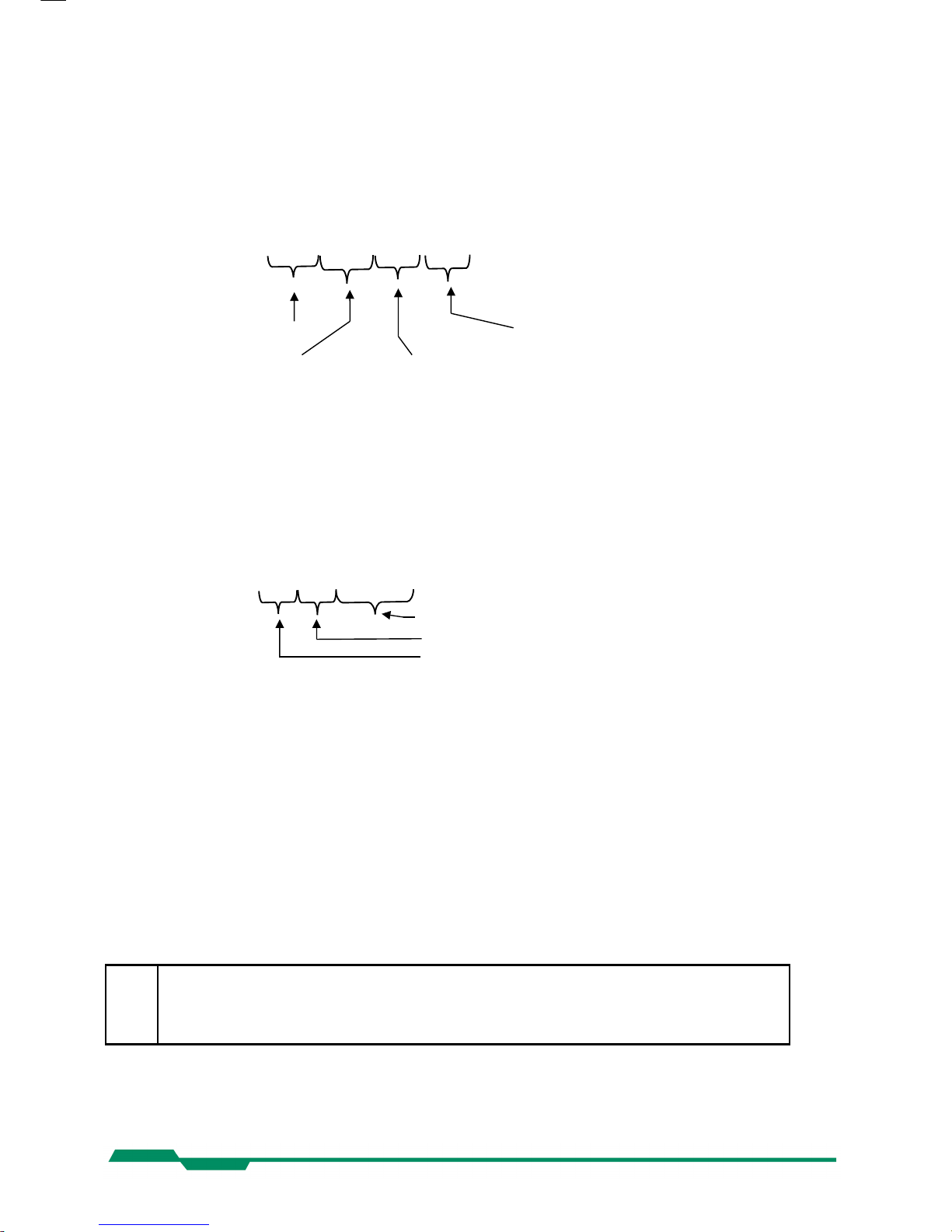
The serial number and the firmware revision can be read with the :v command.
Command: :v
Response(e.g.): #01234-B2.02-V1.18-F1.10
Serial number
of the camera FPGA firmware version
Microcontroller bootloader Microcontroller application
firmware version firmware version
The answer is followed by a CR (0x0d) trailer.
6.2.2 Read identifier, command :V
The identifier offers information about the camera type and camera functions. It consists of 8
bytes, which are delivered as 16 ASCII characters.
Command: :V
Response (e.g.): 1362000003040303
definition of additional functions or features, 4 bytes
reserved bytes
camera type, e.g. 1362 = MC1362
The answer is followed by a CR (0x0d) trailer.
6.2.3 Read camera temperature, command :T
To control the temperature inside , the camera disposes an internal temperature sensor. The
temperature inside the camera can be read out in steps of 1°. The values are delivered in
ASCII characters.
Command: :T
Response(e.g.): 34
The answer is followed by a CR (0x0d) trailer.
The temperature Sensor is able to deliver values of –128°C to +128°C.
Take care that the temperature of the camera does not exceed the specified case temperature range.
15
Page 16
Configuration EoSens CL Camera Manual
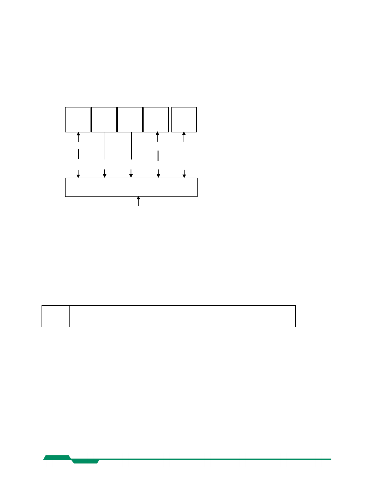
6.3 Profile processing
All camera settings are loaded or stored as complete data blocks (= Profiles).
EoSens full (MC1362-63) has 17 profiles consisting of 8 factory profiles, 8 user profiles and a
power up profile.
EoSens base (MC1360-61) has 9 profiles consisting of 4 factory profiles, 4 user profiles and a
power up profile.
6.3.1 Write user profile, command :p
The actual Profile is transferred to one of the eight user profiles or the PowerUpProfile. Profile
“c“ is the PowerUpProfile.
Command: :p<n> <n> = 0 ... 7, c for EoSens full
<n> = 0 ... 3, c for EoSens base
Issue this command only, if the profile was successfully tested.
6.3.2 Load user profile, command :g
Load one of eight user profiles or the PowerUpProfile to the actual camera profile. Profile “c“ is
the PowerUpProfile
Command: :g<n> <n> = 0 ... 7, c for EoSens full
<n> = 0 ... 3, c for EoSens base
6.3.3 Load factory profile, command :f
The eight factory profiles can be read but not changed by the user.
Command: :f<n> <n> = 0 ... 7, c for EoSens full
<n> = 0 ... 3, c for EoSens base
16
User
profile 0
:pc
:p0
:f0
:gc or
power on
Factory
profile n
User
profile n
Factory
profile 0
Power Up
Profile
:g0
:fn
Camera profile (programs to camera logic)
Configuration commands
:a..z[parameter]
:gn
:pn
Page 17

Configuration EoSens CL Camera Manual
6.4 Output mode
6.4.1 Camera Link® output mode, command :M
Command: :M<x> <x> = 0…7
or: :M?
Response: --* * ACK/NAK if acknowledge on
or: <x> <x> = actual value
Description: This command selects the Camera Link output mode. For example the
mode 0 delivers 2 taps with 8 bit.
Mode Taps x Bits CL- config. Pixelclock Remark
0 2 x 8 base 80 MHz
1 2 x 10 base 80 MHz
2 16 x 1 base 80 MHz optional feature, binarization
3 2 x 8 base 80 MHz optional feature, mask mode
4 4 x 10 medium 80 MHz only EoSens full (MC1362-63)
5 8 x 8 full 80 MHz only EoSens full (MC1362-63)
6 10 x 8 full 75 MHz only EoSens full (MC1362-63)
7 1 x 10 base 80 MHz
6.4.2 Set pixelclock, command :R
Command: :R<xx> <xx> = 3c
hex
, 41
hex
, 46
hex
, 4b
hex
, 50
hex
or: :R?
Response: --* * ACK/NAK if acknowledge on
or: <xx> <xx> = actual value
Description: This command selects the pixelclock of the cameralink interface. As
default all modes work with a pixelclock of 80MHz. (Except of mode 6 with
75MHz). With this setting the full speed of the camera can be achieved.
The clock can be adjusted in 5 MHz steps from 60…80MHz.
Application: Under some circumstances it is helpful to reduce the clock. This is the
case if the framegrabber can’t accept fast pixelclock or if a long or poor
cable is used. Note that a reduced pixelclock results in a lower maximal
framerate. This can be checked with the framerate command.
Note: In mode 6 the value 50
hex
is not valid.
17
Page 18

Configuration EoSens CL Camera Manual
6.4.3 Linescan mode, command :j
Command: :j<x> <x> = 0 for disable, 1 for enable
or: :j?
Response: --* * ACK/NAK if acknowledge on
or: <x> <x> = actual value
Description: This command enables the linescan mode. In this mode the camera
behaves like a linescan camera. In detail this changes the behavior of
FVAL, LVAL and DVAL signals. The following diagrams show a ROI with
a height of 2 lines.
Normal mode
Linescan mode
18
Page 19

Configuration EoSens CL Camera Manual
6.5 Image quality
6.5.1 Digital gain, command :D
Command: :D<xxxx> <xxxx> = 0400 ... 1000
hex
or: :D<x> <x> = 0
or: :D?
Response: --* * ACK/NAK if acknowledge on
or: <xxxx> <xxxx> = actual value
Description: The digital gain can be set from 0400
hex
which is equivalent to gain 1x to
1000
hex
which is equivalent to gain 4x. Setting the gain to 0 switches off
the correction completely.
6.5.2 Blacklevel, command :k
Command: :k<xx> <xx> = 32 ... C8
hex
or: :k?
Response: --* * ACK/NAK if acknowledge on
or: <xx> <xx> = actual value
Description: This command adjusts blacklevel. The value 80
hex
is the factory calibrated
default. Increase or decrease this value slightly to adjust blacklevel.
19
Page 20

Configuration EoSens CL Camera Manual
6.5.3 FPN correction, command :N
Command: :N<x> <x> = 0 or 1
or: :N?
Response: --* * ACK/NAK if acknowledge on
or: <x> <x> = actual value
Description: With this command the column FPN (fixed pattern noise) correction can
be activated or deactivated. At the beginning of each frame, before visible
lines are read out, a fixed voltage is applied at the columns. These values
are read out like real data and are stored inside the camera. When FPN
correction is enabled the stored value is subtracted of each pixel. The advantage is a more homogeneous picture but with a limited dynamic.
Note: This noise is not dynamic but fixed (as the name says). That’s a typical
effect of a CMOS sensor. But the fixed pattern makes it easy to eliminate
this noise completely. The camera does only a column correction. If an
accurate pixel correction of the full frame is required this must be done by
the framegrabber or in the imaging software. To do this it’s best to switch
off the camera’s FPN correction to get the original dynamic. Then a
complete image of a uniform area must be stored as a reference. This
values must be subtracted for each pixel of the frame and the noise will
disappear.
20
Page 21

Configuration EoSens CL Camera Manual
6.6 Image size and position
Image size and position within the Sensor is defined by four parameters:
Block Description Value
<aaa> Address of first pixel x-start 0 ... 4F8
hex (modulo 24)
<bbb> Address of first line y-start 0 ... 3FE
hex
<ccc> x-width x-width 2 ... 500
hex (modulo see table below)
<ddd> y-height y-height 1 ... 400
hex
6.6.1 Setting the ROI, command :d
Setting image size and position - region of interest (ROI):
Command: :d<aaa><bbb><ccc><ddd> values as described above
or: :d?
Response: --* * ACK/NAK if acknowledge on
or: aaabbbcccddd actual value
Note: The x-start is rounded down if not modulo 24. The x-width has a modulo depend -
ing on the actual Camera Link output mode (command :M). If the value does not
fit the modulo the command will return NAK.
Mode (:M) Taps x Bits Modulo x-width Remark
0 2 x 8 2
1 2 x 10 2
2 16 x 1 16 optional feature, binarization
3 2 x 8 * optional feature, mask mode
4 4 x 10 4 only EoSens full (MC1362-63)
5 8 x 8 8 only EoSens full (MC1362-63)
6 10 x 8 10 only EoSens full (MC1362-63)
7 1 x 10 1
* = only full ROI allowed
The ROI change time is 18ms including command transfer at 115kBaud. The new ROI
is synchronized to the next frame so there is an additional delay of max 1 frameperiod.
For fast tracking purposes see also the ROI move mode.
21
Page 22

Configuration EoSens CL Camera Manual
6.6.2 Setting multiple ROI’s, command :L
Command: :L<z><xxx><yyy> <z> = 1…3 window to set
<xxx> = 0…4f8
hex
x-start
<yyy> = 0…3fe
hex
y-start
or: :L<z>? show actual start of window <z>
or: :Ln<a> <a> = 0…3 windows to activate
or: :Ln? show number of active windows
Response: --* * ACK/NAK if acknowledge on
or: xxxyyy actual value
or: a
Description: With this command multiple ROI’s are activated and controlled. EoSens
allows to simultaneously choose up to four individual ROI’s within the
complete frame range. Thus, multiple objects can be captured independ ently at the same time. Normally only one window is active. This is the
default of a=0. With a >=1 up to 3 additional windows can be activated. So
a total of maximal 4 windows can be active. Each window can have its
own start address. The size of the additional windows is the same as the
main ROI.
Note: In contrast to normal mode with x-start modulo of 24 in multiple ROI mode
the x-start modulo is 48 beginning with 0 or 24 depending on the main
ROI. If multiple ROI’s are active also the main ROI is locked to modulo 48.
Start addresses not fitting this modulo will be automatically rounded by the
camera and can be checked with the read command. Note also that when
changing the size of the main ROI the additional ROI’s will be changed
automatically. So take care that these ROI’s will fit into the sensor size.
Also the maximum framerate will decrease if multiple windows are active.
Remark: This mode can not be combined with ROI move mode, x- or y- invert
mode, decimation mode and mask mode.
22
Page 23

Configuration EoSens CL Camera Manual
6.6.3 Setting arbitrary shaped fields of view, command :S (optional feature)
Command: :SC<xxx><yyy><rrr><www> <xxx> = 0…500
hex
; <yyy> = 0…400
hex
<rrr> = 1…300
hex
; <www> = 1…400
hex
or: :SM<aaa><dddd> <aaa> = 0…3ff
hex
; <dddd> = 0…ffff
hex
or: :SE
or: :SV<n> <n> = 0…1 0 = off ; 1 = on
Response: --* * ACK/NAK if acknowledge on
Standard adjustment of the camera using the ROI parameters allows to define rectangular
windows. For windows with different shapes the EoSens offers a feature to create arbitrary
fields of view.
It can be adjusted by a selection mask consisting of 16.384 read tiles. Each tile has a size of
10(H) x 8(V). All 16.384 tiles cover the whole active sensor area with 128x128 tiles.
The camera has a built in algorithm to create a circle mask. With :SC a circle is created and all
tiles that touch that circle are activated. With <xxx> and <yyy> the center of the circle is
defined. The parameter <rrr> defines the radius and <www> defines the width. The circle can
partially be out of the field of view. The internal calculation lasts <1 sec.
To create more arbitrary shapes the command :SM can be used. The first tile in first line is on
address <aaa>=0. Tile 16 is at address <aaa>=1. The first tile in second line is at address
<aaa>=8. Each address covers 16 tiles that can be switched with the data <dddd>.
For example to switch on the tile 16 and 18 in the second line use the command :SM009A000.
Address <aaa> = 0x009 covers the tiles 16..31.
Data <dddd> = 0xA000 in binary notation ‘1010000000000000’ activates the tiles 16 and 18.
The addresses can be randomly accessed and only that tiles that have to be activated must
be written.
To erase all tiles use the :SE command.
For testing purposes the command :SV can be used. When in mode :M0 the activated tiles are
viewed inverted in the picture but all pixels will be output.
To output only the activated tiles mode :M3 must be used.
The programmed settings are volatile and must be reprogrammed after each power up.
Remark: This mode can not be combined with ROI move mode, x- or y- invert mode,
decimation mode and multiple ROI mode.
23
Page 24

Configuration EoSens CL Camera Manual
6.6.4 Setting arbitrary shaped fields of view in compatible mode, command :r (optional
feature)
Command: :r8<x
2x1x0
>
<x2x1x0> range 000h ...03ff
hex
<x1x0> selection byte, bits 7..0, range 00
hex
...0ff
hex
<x2> bit 9..8 = 0 : disable arbitrary window function
<x2> bit 9..8 = 1 : write 2048 selection bytes
<x2> Bit 9..8 = 2 : enable arbitrary window function,
disable write selection byte function
Response: --* * ACK/NAK if acknowledge on
Standard adjustment of the camera using the ROI parameters allows to define rectangular
windows. For windows with different shapes the EoSens offers a feature to create arbitrary
fields of view.
It can be adjusted by a selection mask consisting of 16.384 read tiles. Each tile has a size of
10(H) x 8(V). All 16.384 tiles cover the whole active sensor area with 128x128 tiles.
The selected tiles are summed up in 2.048 selection bytes with 8 bit and can be loaded sequentially via register r8. Each set bit in a selection byte causes the associated tile to be
captured and read out.
The 1. of 2048 selection bytes addresses the leftmost, top pixel group with 10 pixel in the 1.-8.
line (1. selection tile). If bit 1 is set the next 10 pixel of line no. 1-8 are activated. Bit 7 enables
pixel 70..79. The next selection byte, bit 0 addresses pixel 80..89.
To set the arbitrary shaped field of view all 2048 selection bytes must be written. In each byte
at least write bit (bit 8) must be set. After all 2048 selection bytes have been programmed the
write function must be finished by disabling the write function (2049. command).
The whole command list should be stored into a separate configuration file (*.mcf):
byte1 byte2 … byte n byte n+1… byte2048 byte2049
:r8100 :r8100 … :r81ff :r81ff … :r8100 :r8200
One command is only complete, if it starts with a colon, “r8” and then 2 ASCII characters. To
get a better readability of the list it is recommended to start with a new line after 16 commands
(CR+LF). The single commands :r8200 and :r8000 will enable and disable the function.
When in mode :M0 the activated tiles are viewed inverted in the picture but all pixels will be
output. To output only the activated pixels mode :M3 must be used.
The programmed settings of the 2048 bytes are volatile and must be programmed new after
each power up. The file may be written with the camera tool using the function “Write file to
camera”.
Do NOT use this command for new applications. Use the :S command instead.
24
Page 25

Configuration EoSens CL Camera Manual
6.6.5 ROI move mode with external CCx input, command :l
Command: :l<n><y> <n> = 0…3 0=off ; 1=y ; 2=x ; 3=x+y
<y> = 1…fh step y-direction
or: :l?
Response: --* * ACK/NAK if acknowledge on
or: <ny> actual value
Description: This feature allows to move the actual ROI with the CC2…CC4 inputs of
the cameralink interface. The signal can be generated by the framegrabber itself or by external signals that are input to the grabber. The stepping
in x-direction is always 24 pixels, the stepping in y-direction can be
selected from1-15 with the <y> parameter. Move will always be in positive
direction. If the right side or the bottom of the sensor is reached no action
will be on further input signals. With CC4 the position is reset to the
original position; This is not necessarily the top left edge of the sensor.
Signals: CC2 = y-increment
CC3 = x-increment
CC4 = reset to original position
Note: The input frequency can be up to 20kHz. The signals will be added
between the frames. The added move signals are synchronized to the
next frame. The internal process time is 500µs where no signals can be
counted. This is immediately after the exposure meaning that signals input
before 500µs after the falling edge of ‘strobe’ will be lost.
Example: ROI 1280x390 pixel at 287fps and 1ms exposure time. Pulses with 20kHz.
There are 3ms time to send pulses. In this time 60 pulses can be sent
from frame to frame.
So the possible 634 lines will take 38ms to move and 11 frames will be
exposed in this time.
Remark: This mode can not be combined with multiple ROI mode, x- or y- invert
mode, decimation mode and mask mode.
25
Page 26

Configuration EoSens CL Camera Manual
6.6.6 Invert readout in x- and or y-direction, command :o
Command: :o<x> <x> = 0…3 0=off ; 1=x ; 2=y ; 3=x+y
or: :o?
Response: --* * ACK/NAK if acknowledge on
or: <x> actual value
Description: This feature allows to invert the frame readout in x- and or y-direction.
Remark: This mode can not be combined with ROI move mode, multiple ROI
mode, decimation mode and mask mode.
6.6.7 Decimation mode (Subsampling), command :Q
Command: :Q<x> <x> = 0…1 0=off ; 1=on
or: :Q?
Response: --* * ACK/NAK if acknowledge on
or: <x> actual value
Description: With this feature enabled the sensor skips every other row and column.
Therefore the maximum width is 640 pixel and the maximum height is 512
pixel. The advantage is that a lens with the same focal distance can cover
the identical image size but with a higher framerate.
Note: A ROI of 640x512 covers the whole sensor area and equals the repro-
duction scale of 1280x1024 in normal mode. Switching on/off this mode
halves/doubles the output image size.
Limitation: The ROI x-start position should be zero because else the internal FPN
correction does not work correct. If a x-start position >0 is needed the
internal FPN correction should be turned off. If necessary a correction
must be done in the frame grabber or in software.
Remark: This mode can not be combined with ROI move mode, multiple ROI
mode, x- or y- invert mode and mask mode.
original used pixels output
26
Page 27

Configuration EoSens CL Camera Manual
6.7 Framerate and shutter
6.7.1 Setting the framerate, command :q
Command: :q<xxxxxx> <xxxxxx> = 1...13880
hex
or: :q?
Response: --* * ACK/NAK if acknowledge on
or: <xxxxxx>' '<ss>'-'<zzzzzz> <xxxxxx> = actual value
<ss> = minimal value
<zzzzzz> = maximal value
Description: This command sets the framerate in frames per second for free run mode.
The valid range depends on ROI and tap mode and can be obtained with
‘?’ as parameter.
6.7.2 Setting the shuttertime, command :t
Command: :t<xxxxxx> <xxxxxx> = 2...F4240
hex
or: :t?
Response: --* * ACK/NAK if acknowledge on
or: <xxxxxxx>' '<ss>-<zzzzzz> <xxxxxx> = actual value
<ss> = minimal value
<zzzzzz> = maximal value
Description: This command sets the shuttertime in microseconds for free run and sync
with timer mode. Depending on the tap mode and ROI the minimal and
maximal shuttertime can vary. Use the ‘?’ parameter for the valid range.
The maximal exposure time is 1/framerate.
27
Page 28

Configuration EoSens CL Camera Manual
6.7.3 Setting the slopes for dynamic range adjustment, command :i
Command: :i<s><x>
or: :i<s><xx>
or: :i<s>?
<s> = 'n' ==> <x> = 1...3 (Number of slopes)
<s> = 'd',' t' ==> <xx> = 1...63h
hex
('d'ual or 't'riple
slope in percent)
Response: --* * ACK/NAK if acknowledge on
or: <x> (Number of Slopes)
or: <xx>' '<yy>-<zz> <xx> = actual value
<yy> = minimal value
<zz> = maximal value
Description: This command sets the multiple slope function for dynamic range adjust-
ment. Through 2 selectable steps, the camera’s dynamic range adjustment option allows to approach the CMOS sensor’s linear range into a
dynamic range corresponding to the non-linear human eye. Consequently,
EoSens provides definite image details even in case of extreme dark-light
contrasts, which means an invaluable benefit exceptionally in image processing. With 'n'=1 the multiple slopes are deactivated and the frame will
be exposed with the whole shuttertime. With activated slopes the bright
pixels will be reset after <xx>percent of the shuttertime. The dual value
must be smaller than triple. Depending on the mode, ROI and shuttertime
the first slope can eventually not start at 1 percent. The valid range can be
read out with the '?' argument. Only if valid values are set the function can
be activated. See also 'last error' command.
multiple slope off triple slope activated
28
Page 29

Configuration EoSens CL Camera Manual
6.7.4 Non destructive readout for multiple pixel exposure, command :O
Command: :O<x> <x> = 1…7
or: :O?
Response: --* * ACK/NAK if acknowledge on
or: <x> actual value
Description: This command controls the non destructive readout mode. If desired, pixel
exposure can be accumulated up to 7 times, resulting in increasing image
exposures. The optimally exposed image can be selected for further processing. At indefinite lighting conditions, as in 24 hour outdoor applications, EoSens becomes the high speed camera that spots everything.
With x=1 after every frame the pixels are reset (normal operation). With
x>1 all pixels will be read out multiple times (max. 7) after they are reset.
So for low light the last samples are useful and for high light levels the first
samples are useful.
Note: Only the first image is exposed with the selected shutter time. The follow-
ing images will be exposed with the frametime (1/framerate). This is
because once the shutter opens it will remain open until all of the
maximum 7 images are taken.
29
Page 30

Configuration EoSens CL Camera Manual
6.8 Exposure control
Exposure control is selected with commands :h, :H and :t
Command Description
:h Select exposure mode
:H Trigger edge select
:t Set exposure time
6.8.1 Type of exposure, commands :h, :H and :t
The EoSens can expose the images in free run mode or with an external signal on CC1. The
external modes are used to synchronize EoSens cameras to each other or to an external
event. See also the timing diagrams in the technical data section of this manual.
The following commands select exposure type:
Mode description Mode Edge Shuttertime
Free run with electronic shutter :h0 -- :t<xxxxxx>
Pulsewidth, positive edge :h1 :H0 Pulsewidth
Pulsewidth, negative edge :h1 :H1 Pulsewidth
External sync with internal timer,
positive edge
:h2 :H0 :t<xxxxxx>
External sync with internal timer,
negative edge
:h2 :H1 :t<xxxxxx>
6.8.2 Free run with electronic shutter
In free run mode the framerate and shuttertime can be selected with camera settings. Depending on tap mode and ROI the framerate can be set from 1…120000 fps and the exposure time
can be set from 2µs to 1s.
30
Page 31

Configuration EoSens CL Camera Manual
6.8.3 Pulsewidth mode
In this mode an external signal starts exposure and the exposed image is output immediately
after the exposure ends. Exposure time is defined by the width of the external EXP (CC1)
signal. The exposure of the next image can be started while the last image is transferred or at
a later time.
6.8.4 External sync with internal timer
In this mode an external signal starts exposure and the exposed image is output immediately
after the exposure ends. Exposure time is defined by an internal timer. The exposure of the
next image can be started while the last image is transferred or at a later time.
6.9 Other
6.9.1 In frame counter, command :u
Command: :u<x> <x> = 0...1 0 = off
or: :u? 1 = on
Response: --* * ACK/NAK if acknowledge on
or: <x>
Description: If a sequence of frames is to be recorded for long time at a high framerate,
it can be useful to mark the images for later identification or check for
completeness. EoSens has a 32-Bit image counter whose count can
replace the first four pixel of every image. It is incremented by every new
image
6.9.2 Test image, command :n
Command: :n<x> <x> = 0...1 0 = power down + test image
or: :n? 1 = normal operation
Response: --* * ACK/NAK if acknowledge on
or: <x>
Description: For testing of camera logic and video data transmission, sensor data can
be replaced by an internal gray scale pattern with pixel values of 0..255.
With x=0 the camera sends a grayscale that is slowly rolling from right to
left. This mode can also be used to save power consumption because the
image sensor will be set to standby mode.
31
Page 32

Configuration EoSens CL Camera Manual
6.9.3 Setting threshold mode, command :K (optional feature)
Command: :K<s><x>
or: :K<s><xxx>
or: :K<s>?
<s> = 'n' ==> <x> = 0...1 threshold off or on
<s> = 'v' ==> <xxx> = 0...3ff
hex
threshold value
Response: --* * ACK/NAK if acknowledge on
or: <x> threshold off or on
or: <xxx> actual threshold value
Description: With this command the threshold mode can be activated. All pixels above
the threshold level in the image will be output as white while all pixels
below will be output as black. The threshold relates to the 10 bit sensor
data. This feature is especially useful with the mode 2 (16 tap x 1 bit)
threshold off threshold on
6.9.4 Get last error, command :B
Command: :B
Response: 'OK' or 'ERROR: xx message'
Description: With this command the status of the camera after power up or the last
command can be read out. If a command returns NAK maybe the reason
can be found.
32
Page 33

Configuration EoSens CL Camera Manual
6.9.5 Reset and configuration of the internal FPGA, command :c
Command: :c
Response: --* * ACK/NAK if acknowledge on
Description: The command :c executes a reset in the camera. The FPGA will be re
configured and all internal registers reloaded with the last saved
PowerUpProfile. The FPGA is also configured after each power up.
6.9.6 Command acknowledge flag, command :A
Command: :A<x> <x> = ‘y’ or ‘Y’ for ON
or: :A? ‘n’ or ‘N’ for OFF
Response: --* * ACK/NAK if acknowledge on
or: <x> ‘y’ or ‘n’
Description: This command switches on or off the command acknowledge. If set to on
every write command returns an ACK (0x06) if the command was processed successful or NAK (0x15) if the command failed to execute.
6.9.7 Setting the baudrate, command :b
Command: :b<n> <n> = 0 -> 9600 Baud (default)
or: :b? 1 -> 19200 Baud
2 -> 38400 Baud
3 -> 57600 Baud
4 -> 19200 Baud
Response: --* * ACK/NAK if acknowledge on
or: <n> actual baudrate
Description: The command :b sets the baudrate for the camera control communication.
Note: After a reset or a power up the camera always defaults to a baudrate of
9600 Baud.
33
Page 34

MC ControlTool EoSens CL Camera Manual
7 MC ControlTool
The EoSens configuration tool must be installed on a Windows PC by means of the setup
software. See also www.mikrotron.de to download the latest version.
This software provides an almost self explaining user interface to modify any camera parameter.
Since the serial interface is integrated in the CameraLink® interface you do not need any other
additional cable.
34
Page 35

Firmware EoSens CL Camera Manual
8 Firmware
The camera possesses programmable devices, which are working with some firmware
packages. New cameras were programmed with all needed firmware packages and will not
need any update.
For customized firmware or additional features the camera offers the possibility to update the
firmware. The procedure of updating depends on the firmware package.
8.1 Microcontroller firmware
The microcontroller works with 2 programs, the bootloader and the application program.
The bootloader is the basic program of the microcontroller, which ensures some basic func tions (e.g. communication, loading application program) and cannot be changed or updated. In
standard use of the camera it will never work in the bootloader program. It’s only used for
updating the application program.
The application program is the active microcontroller program in the camera, which supports
communication, data handling and FPGA program updates.
See description of update procedure in chapter “Firmware update procedure”.
8.2 FPGA firmware
The camera logic is integrated into a FPGA’s (Field Programmable Gate Array), which’s configuration is stored in an EEPROM. Upon power up or reset the FPGA is loaded with this con figuration. Configuration data can be downloaded via the serial interface. Mikrotron may
provide configuration files (*.ibf) on request. After download of configuration data, this data is
permanently stored in EEPROM and the FPGA is configured with the new data. Besides a
power cycle or the :c command can be used to reconfigure the FPGA with the internally
stored configuration data.
See description of update procedure in chapter “Firmware update procedure”.
35
Page 36

Firmware EoSens CL Camera Manual
8.3 Firmware update procedure
The EoSens firmware consists of two files. Mikrotron always provides these files as one
package. Be sure to always update all two firmwares. Do not mix firmwares of different
packages. Before you begin please ensure that you have the adequate application firmwares
to load. The files may be packed in a .zip file and you have to unzip them first.
For EoSens CL you need the following files:
• µController..……...... MC1362M622Axxx.ibf
• FPGA....................... MC136xM651Fxxx.ibf
The last ‘xxx’ represents the version number. For example ‘116’ is version number ‘1.16’.
Once started YOU CANNOT UNDO THIS COMMAND.
Also note that your saved power up and user profiles will be overwritten with
standard profiles.
• Start camera control tool and select “EoSens” camera. Wait until the info screen
displays serial no. and firmware version.
• Select in menu “Tools” - “Update camera”:
36
Page 37

Firmware EoSens CL Camera Manual
• In the drop down menu „Mode“ select the desired device to update:
• Click “Select file” and choose the appropriate file (see above):
• Click “Send” and the file transfer will start immediately:
• While loading the camera LED will blink red:
Upload of *.ibf files via serial link takes several minutes depending on the used
baudrate. There should be no loss of power or communication during this time! Also
no other activity should be made on the PC while doing the upload.
37
Page 38

Firmware EoSens CL Camera Manual
• Wait until file transfer has finished and the camera status LED stays on. If the upload
was successful, the LED will turn to green, otherwise it will be red.
• If the update was successful you can proceed with the next firmware. Otherwise check
the troubleshooting in the next chapter. Repeat these steps for sensor FPGA by
choosing the „Mode“ in the drop down menu.
• After all modules have been updated verify the versions in “Eo Sens” info screen. The
new firmware version will be displayed. If the version is identical to the expected the
camera is ready to use for capturing images.
38
Page 39

Firmware EoSens CL Camera Manual
8.4 Firmware update troubleshooting
If the update procedure was not successful the camera should be powered off and on and the
control tool should be restarted. There are two possible errors. When repeating the update the
baudrate should be left at 9600.
1. Possible error: The microcontroller was not loaded successful and the camera has
only it’s bootloader active. The camera confirms this with 1x red blink after power up. In
the camera connect window ‘Bootloader’ will appear instead of the camera name:
Solution: Connect to the camera and the tool will automatically start with the “Update
µController” dialog. Start the microcontroller update as described above. After successful update close the dialog and the tool will restart with the connect dialog showing the
camera.
39
Page 40

Firmware EoSens CL Camera Manual
2. Possible error: The FPGA program was not loaded successful. The camera
confirms this with 3x red blink after power up. The ‘Info’ tab of the control tool shows
‘F0.00’.
Solution: In this case just repeat the ‘Update FPGA firmware’ procedure.
40
Page 41

Technical Data EoSens CL Camera Manual
9 Technical Data
9.1 Overview
MC1360 / 62
MC1361 / 63
Monochrome
Bayer Filter
Number of pixel 1280 x 1024
Pixel size 14 x 14 µm
Active area 17.92 (H) x 14.34 (V) mm
Fill factor 40%
Response 25 V/lux.s @ 550nm
Spectral response 400…720nm monochrome
400…670nm color
Shutter Electronic „Freeze Frame“ Shutter
Trigger Asynchronous shutter, shutter time select-
able with internal timer or by pulse width
of trigger signal
Internal dynamic 58 dB
Pixel saturation level 30000e¯
Power supply 8…24 V
Power consumption max.
Thermal resistance typ.
5 W
0.17°/W
Serial data link RS-644 with Camera Link
®
9,6…115 kBd, 8 bits, 1 stop bit, no parity
Digital video
MC1362-63
MC1360-61
Camera Link®, Base or Full configuration
Camera Link®, Base configuration
Case temperature +5…50°C
Shock & vibration 70g, 7grms
Dimensions (WxHxD) 63 x 63 x 47 mm
Case temperature +5…+50° C
Weight ca. 300 g
Lens mount C-/F-mount (depending on adapter)
41
Page 42

Technical Data EoSens CL Camera Manual
9.2 Sensor defect specifications
Parameter Description Limit
BrightPix
Amount of bright pixels (response higher then half
scale) in a dark image. Dark image must first be FPN
corrected.
< 10
DarkMeanOutput Average value of a dark image (10-bit scale). 0 < x < 235
50%MeanOutput Average value of a half scale image (10-bit scale). 390 < x < 547
FPN
Fixed pattern noise of a dark image should be smaller
than 3.1% of the signal swing
< 3.1%
TotDefects
Amount of defect pixels in a half scale image. A
defect pixel is defined as a pixel that has a response
that is 20% off the median response of all pixels. The
half scale image must be FPN corrected.
< 20
BadColumnOutput
Amount of bad columns in a half scale image. A bad
column is defined as a column that has a response
that is 10% off the median of the surrounding 40
columns. The half scale image needs to be FPN
corrected.
0
BadRow
Amount of bad rows in a half scale image. A bad row
is defined as a row that has a response that is 10%
off the median of the surrounding 40 rows. The half
scale image needs to be FPN corrected.
0
Cluster
Amount of clusters allowed
See note 1.
0
Coverglass
Dig/Scratch
Uniform illumination. Test sensor for defective pixels.
Defects on cover glass will generate defect pixels. No
defect pixels may be visible.
0
Measurement conditions:
1. Illumination source: High brightness led light source (white) Using a pinhole to imitate
the lens setup in the application. F=5.4
2. Temperature is 25ºC (logged during the test program) and 30 ºC on
wafer. Dark current limit is set at 30 ºC
3. Definition of operation conditions:
Nominal clock frequency is 310 MHz.
Unity Gain
Power supplies as specified in the datasheet (recommended operation conditions)
Integr. times:Dark image short IT: 4μs, Dark image long IT: 1s, Other images: 2ms
Note 1: A cluster is defined as a group of minimal 2 and maximum 4 neighboring defect pixels (top, bottom or
side; not diagonal). Clusters that exceed the maximum of 4 defect pixels are not allowed at all.
42
Page 43

Technical Data EoSens CL Camera Manual
9.3 Spectral response
The charts below show the sensitivity of the monochrome and the color sensor with a bayer
pattern filter on the sensor glass lid. The color camera is by default equipped with a UV/IR cut
filter with a transmittance of 370-670nm resulting in a sensitivity shown in the second chart.
By request all types of cameras can be delivered with or without UV/IR cut filter.
Sensitivity of camera without UV/IR cut filter (standard monochrome version)
Sensitivity of camera with UV/IR cut filter (standard color version)
43
Page 44

Technical Data EoSens CL Camera Manual
9.4 Bayer pattern filter
The EoSens color camera has a bayer pattern filter on the sensor glass lid. To get the color information the imaging software must decode the information. The pattern beginning from first
row, first column is:
Green Blue
Red Green
Because the pattern must always start at the same field with a color camera only even height
and even offset-y is possible. The camera will automatically round down if odd values are
entered. Also mind if using the invert readout function the pattern must be inverted too.
44
Page 45
Technical Data EoSens CL Camera Manual
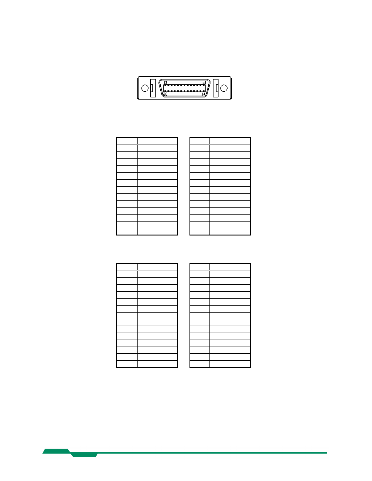
9.5 Connector pinning
9.5.1 Camera Link® connector, MDR-26
„Base Camera Link®“ pinning:
pin signal pin signal
1 GND 14 GND
2 X0- 15 X0+
3 X1- 16 X1+
4 X2- 17 X2+
5 XCLK- 18 XCLK+
6 X3- 19 X3+
7 SERTC+ 20 SERTC8 SERTFG- 21 SERTFG+
9 CC1- 22 CC1+
10 CC2+ 23 CC211 CC3- 24 CC3+
12 CC4+ 25 CC413 GND 26 GND
„Full Camera Link®“ pinning:
pin signal pin signal
1 GND 14 GND
2 Y0- 15 Y0+
3 Y1- 16 Y1+
4 Y2- 17 Y2+
5 YCLK- 18 YCLK+
6 Y3- 19 Y3+
7 100 Ω
Term.
20 100 Ω Term
8 Z0- 21 Z0+
9 Z1- 22 Z1+
10 Z2- 23 Z2+
11 ZCLK- 24 ZCLK+
12 Z3- 25 Z3+
13 GND 26 GND
Manufacturer: 3M
Order-Nr.: 10226-6212VC
45
Page 46

Technical Data EoSens CL Camera Manual
9.5.2 Circular power connector, 6-pin
Pin Signal Voltage level
1 VCC 8 - 24V DC
2 VCC 8 - 24V DC
3 STROBE_OUT LVTTL 3.3V
4 DGND*
5 GND
6 GND
*DGND ... digital GND for signal STRB
Manufacturer: Hirose
Order no.: HR10A-7P-6S
Before applying power to the camera we strongly recommend to verify the used
pins of the power connector, the polarity (+/-) of the leads and the supply voltage.
The camera may only be used with a supply voltage according to the camera specification. Connecting a lower or higher supply voltage, AC voltage, reversal
polarity or using wrong pins of the power connector may damage the camera. If
doing so, the warranty will expire immediately.
46
Page 47

Technical Data EoSens CL Camera Manual
9.6 Camera Link® bit Assignments
9.6.1 Base Camera Link® 2*8/10 - bit Assignment
The following table shows the bit assignment of two adjacent pixel, eight or ten bits each. All unused bits are set
to logical LOW level, the SPARE outputs are set to logical HIGH level.
Plug 1, Camera Link® X, 2*8-bit Plug 1, Camera Link® X, 2*10-bit
Port Tx Signal Port Tx Signal
A0 0 D0 A0 0 D0
A1 1 D1 A1 1 D1
A2 2 D2 A2 2 D2
A3 3 D3 A3 3 D3
A4 4 D4 A4 4 D4
A5 6 D5 A5 6 D5
A6 27 D6 A6 27 D6
A7 5 D7 (msb) A7 5 D7
B0 7 D8 A8 7 D8
B1 8 D9 A9 8 D9 (msb)
B2 9 D10 LOW 9 LOW
B3 12 D11 LOW 12 LOW
B4 13 D12 B8 13 D18
B5 14 D13 B9 14 D19 (msb)
B6 10 D14 LOW 10 LOW
B7 11 D15 (msb) LOW 11 LOW
LOW 15 LOW B0 15 D10
LOW 18 LOW B1 18 D11
LOW 19 LOW B2 19 D12
LOW 20 LOW B3 20 D13
LOW 21 LOW B4 21 D14
LOW 22 LOW B5 22 D15
LOW 16 LOW B6 16 D16
LOW 17 LOW B7 17 D17
LVAL 24 LVAL LVAL 24 LVAL
FVAL 25 FVAL FVAL 25 FVAL
DVAL 26 DVAL DVAL 26 DVAL
SPARE 23 HIGH SPARE 23 HIGH
TxClk TxClk
47
Page 48

Technical Data EoSens CL Camera Manual
9.6.2 Full Camera Link® 8*8-bit Assignment
The following table shows the bit assignment of eight adjacent pixel. All unused bits are set to logical LOW level,
the SPARE outputs are set to logical HIGH level.
Plug 1, Camera Link® X Plug 2, Camera Link® Y Plug 2, Camera Link® Z
Port Tx Signal Port Tx Signal Port Tx Signal
A0 0 D0 D0 0 D24 G0 0 D48
A1 1 D1 D1 1 D25 G1 1 D49
A2 2 D2 D2 2 D26 G2 2 D50
A3 3 D3 D3 3 D27 G3 3 D51
A4 4 D4 D4 4 D28 G4 4 D52
A5 6 D5 D5 6 D29 G5 6 D53
A6 27 D6 D6 27 D30 G6 27 D54
A7 5 D7 (msb) D7 5 D31 (msb) G7 5 D55 (msb)
B0 7 D8 E0 7 D32 H0 7 D56
B1 8 D9 E1 8 D33 H1 8 D57
B2 9 D10 E2 9 D34 H2 9 D58
B3 12 D11 E3 12 D35 H3 12 D59
B4 13 D12 E4 13 D36 H4 13 D60
B5 14 D13 E5 14 D37 H5 14 D61
B6 10 D14 E6 10 D38 H6 10 D62
B7 11 D15 (msb) E7 11 D39 (msb) H7 11 D63 (msb)
C0 15 D16 F0 15 D40 LOW 15 LOW
C1 18 D17 F1 18 D41 LOW 18 LOW
C2 19 D18 F2 19 D42 LOW 19 LOW
C3 20 D19 F3 20 D43 LOW 20 LOW
C4 21 D20 F4 21 D44 LOW 21 LOW
C5 22 D21 F5 22 D45 LOW 22 LOW
C6 16 D22 F6 16 D46 LOW 16 LOW
C7 17 D23 (msb) F7 17 D47 (msb) LOW 17 LOW
LVAL 24 LVAL LVAL 24 LVAL LVAL 24 LVAL
FVAL 25 FVAL FVAL 25 FVAL FVAL 25 FVAL
DVAL 26 DVAL DVAL 26 DVAL DVAL 26 DVAL
SPARE 23 HIGH SPARE 23 HIGH SPARE 23 HIGH
TxClk TxClk TxClk
48
Page 49

Technical Data EoSens CL Camera Manual
9.6.3 10*8-bit assignment
The below table shows the assignment of 10 adjacent pixel, 8-Bit each. This assignment is
compatible to Baslers A504 camera.
Plug 1, Camera Link® X Plug 2, Camera Link® Y Plug 2, Camera Link® Z
Port Tx Signal Port Tx Signal Port Tx Signal
A1 0 D0_0 D3 0 D3_2 G6 0 D6_5
A2 1 D0_1 D4 1 D3_3 G7 1 D6_6
A3 2 D0_2 D5 2 D3_4 G8 2 D6_7 (msb)
A4 3 D0_3 D6 3 D3_5 H1 3 D7_0
A5 4 D0_4 D7 4 D3_6 H2 4 D7_1
A6 5 D0_5 D8 5 D3_7 (msb) H3 5 D7_2
A7 6 D0_6 E1 6 D4_0 H4 6 D7_3
A8 7 D0_7 (msb) E2 7 D4_1 H5 7 D7_4
B1 8 D1_0 E3 8 D4_2 H6 8 D7_5
B2 9 D1_1 E4 9 D4_3 H7 9 D7_6
B3 10 D1_2 E5 10 D4_4 H8 10 D7_7 (msb)
B4 11 D1_3 E6 11 D4_5 I1 11 D8_0
B5 12 D1_4 E7 12 D4_6 I2 12 D8_1
B6 13 D1_5 E8 13 D4_7 (msb) I3 13 D8_2
B7 14 D1_6 F1 14 D5_0 I4 14 D8_3
B8 15 D1_7 (msb) F2 15 D5_1 I5 15 D8_4
C1 16 D2_0 F3 16 D5_2 I6 16 D8_5
C2 17 D2_1 F4 17 D5_3 I7 17 D8_6
C3 18 D2_2 F5 18 D5_4 I8 18 D8_7 (msb)
C4 19 D2_3 F6 19 D5_5 J1 19 D9_0
C5 20 D2_4 F7 20 D5_6 J2 20 D9_1
C6 21 D2_5 F8 21 D5_7 (msb) J3 21 D9_2
C7 22 D2_6 G1 22 D6_0 J4 22 D9_3
C8 23 D2_7 (msb) G2 23 D6_1 J5 23 D9_4
LVAL 24 LVAL G3 24 D6_2 J6 24 D9_5
FVAL 25 FVAL G4 25 D6_3 J7 25 D9_6
D1 26 D3_0 G5 26 D6_4 J8 26 D9_7 (msb)
D2 27 D3_1 LVAL 27 LVAL LVAL 27 LVAL
TxClk TxClk TxClk
49
Page 50

Technical Data EoSens CL Camera Manual
9.7 Timing diagrams
9.7.1 Free run with electronic shutter
In this mode framerate and exposure time is controlled by the camera. At the strobe output (in power connector)
there is a high signal while the camera exposes a picture.
9.7.2 Pulsewidth mode
In this mode framerate and exposure time is controlled by the framegrabber with the CC1 (CameraLink) camera
input. The time t_min (that defines the framerate) must not be smaller than t_out (which is the output time for one
frame).
9.7.3 External sync with internal timer
In this mode the framerate is controlled by the framegrabber while the exposure time is controlled by the camera.
50
Page 51

Technical Data EoSens CL Camera Manual
9.8 Mechanical dimensions
51
 Loading...