

EoSens 3CXP Camera
Reference Guide V2.3

Table of Content
Table of Content
Before You Start
About This Reference Guide . . . . . . . . . . . . . . . . . . . . . . . . . . . . . . . . . . . . . . . . . . . . . . . . 1-2
Tips, Remarks, Notes and Warnings. . . . . . . . . . . . . . . . . . . . . . . . . . . . . . . . . . . . . . . . 1-2
Registered Trademarks. . . . . . . . . . . . . . . . . . . . . . . . . . . . . . . . . . . . . . . . . . . . . . . . . . 1-3
Conformity and Use . . . . . . . . . . . . . . . . . . . . . . . . . . . . . . . . . . . . . . . . . . . . . . . . . . . . . . 1-3
Supplements . . . . . . . . . . . . . . . . . . . . . . . . . . . . . . . . . . . . . . . . . . . . . . . . . . . . . . . . . . 1-4
For customers in Canada . . . . . . . . . . . . . . . . . . . . . . . . . . . . . . . . . . . . . . . . . . . . . . . . . . . . .1-4
Pour les utilisateurs au Canada . . . . . . . . . . . . . . . . . . . . . . . . . . . . . . . . . . . . . . . . . . . . . . . . 1-4
Life Support Applications . . . . . . . . . . . . . . . . . . . . . . . . . . . . . . . . . . . . . . . . . . . . . . . . . . . . . 1-4
Warranty and Non-Warranty Clause . . . . . . . . . . . . . . . . . . . . . . . . . . . . . . . . . . . . . . . . . . 1-5
EU Declaration of Conformity
EU-Konformitätserklärung . . . . . . . . . . . . . . . . . . . . . . . . . . . . . . . . . . . . . . . . . . . . 1-6
Introduction
Overview . . . . . . . . . . . . . . . . . . . . . . . . . . . . . . . . . . . . . . . . . . . . . . . . . . . . . . . . . . . . . . . 2-2
Scope of Delivery. . . . . . . . . . . . . . . . . . . . . . . . . . . . . . . . . . . . . . . . . . . . . . . . . . . . . . . . . 2-4
Optional Accessories. . . . . . . . . . . . . . . . . . . . . . . . . . . . . . . . . . . . . . . . . . . . . . . . . . . . 2-4
System Requirements . . . . . . . . . . . . . . . . . . . . . . . . . . . . . . . . . . . . . . . . . . . . . . . . . . . . . 2-7
The 3CXP Camera
Camera Description. . . . . . . . . . . . . . . . . . . . . . . . . . . . . . . . . . . . . . . . . . . . . . . . . . . . . . . 3-2
Operating Temperature. . . . . . . . . . . . . . . . . . . . . . . . . . . . . . . . . . . . . . . . . . . . . . . . . . 3-3
Additional Cooling . . . . . . . . . . . . . . . . . . . . . . . . . . . . . . . . . . . . . . . . . . . . . . . . . . . . . . 3-3
Interfaces of the Camera . . . . . . . . . . . . . . . . . . . . . . . . . . . . . . . . . . . . . . . . . . . . . . . . . . . 3-4
Connecting a Frame Grabber . . . . . . . . . . . . . . . . . . . . . . . . . . . . . . . . . . . . . . . . . . . . . 3-6
DIN Connector . . . . . . . . . . . . . . . . . . . . . . . . . . . . . . . . . . . . . . . . . . . . . . . . . . . . . . . . . . . . . 3-6
Connecting an External Power Supply or I/O Signals. . . . . . . . . . . . . . . . . . . . . . . . . . . 3-8
12 Pin Hirose Connector and I/O Signals . . . . . . . . . . . . . . . . . . . . . . . . . . . . . . . . . . . . . . . . . 3-9
6 Pin Hirose and I/O Signals . . . . . . . . . . . . . . . . . . . . . . . . . . . . . . . . . . . . . . . . . . . . . . . . . 3-10
Status LED. . . . . . . . . . . . . . . . . . . . . . . . . . . . . . . . . . . . . . . . . . . . . . . . . . . . . . . . . . . . . 3-11
Resolution and Speed . . . . . . . . . . . . . . . . . . . . . . . . . . . . . . . . . . . . . . . . . . . . . . . . . . . . 3-12
Cleaning Sensor and Lens. . . . . . . . . . . . . . . . . . . . . . . . . . . . . . . . . . . . . . . . . . . . . . . . . 3-12
First Steps
Connect Camera and Image Processing System . . . . . . . . . . . . . . . . . . . . . . . . . . . . . . . . 4-2
Power-up Profile . . . . . . . . . . . . . . . . . . . . . . . . . . . . . . . . . . . . . . . . . . . . . . . . . . . . . . . . . 4-3
Configuring the Camera. . . . . . . . . . . . . . . . . . . . . . . . . . . . . . . . . . . . . . . . . . . . . . . . . . . . 4-4
Reading the XML File . . . . . . . . . . . . . . . . . . . . . . . . . . . . . . . . . . . . . . . . . . . . . . . . . . . . . 4-5
MIKROTRON GmbH TOC-1

Table of Content
Acquisition Control
Acquistion Control . . . . . . . . . . . . . . . . . . . . . . . . . . . . . . . . . . . . . . . . . . . . . . . . . . . . . . . . 5-2
AcquisitionMode . . . . . . . . . . . . . . . . . . . . . . . . . . . . . . . . . . . . . . . . . . . . . . . . . . . . . . . 5-2
AcquisitionStart . . . . . . . . . . . . . . . . . . . . . . . . . . . . . . . . . . . . . . . . . . . . . . . . . . . . . . . . 5-3
AcquisitionStop . . . . . . . . . . . . . . . . . . . . . . . . . . . . . . . . . . . . . . . . . . . . . . . . . . . . . . . . 5-3
TriggerSelector . . . . . . . . . . . . . . . . . . . . . . . . . . . . . . . . . . . . . . . . . . . . . . . . . . . . . . . . 5-4
TriggerMode . . . . . . . . . . . . . . . . . . . . . . . . . . . . . . . . . . . . . . . . . . . . . . . . . . . . . . . . . . 5-4
TriggerSource . . . . . . . . . . . . . . . . . . . . . . . . . . . . . . . . . . . . . . . . . . . . . . . . . . . . . . . . 5-5
TriggerSoftware. . . . . . . . . . . . . . . . . . . . . . . . . . . . . . . . . . . . . . . . . . . . . . . . . . . . . . . . 5-5
TriggerActivation . . . . . . . . . . . . . . . . . . . . . . . . . . . . . . . . . . . . . . . . . . . . . . . . . . . . . . 5-6
ExposureMode . . . . . . . . . . . . . . . . . . . . . . . . . . . . . . . . . . . . . . . . . . . . . . . . . . . . . . . . 5-7
ExposureTime. . . . . . . . . . . . . . . . . . . . . . . . . . . . . . . . . . . . . . . . . . . . . . . . . . . . . . . . . 5-7
ExposureTimeMax . . . . . . . . . . . . . . . . . . . . . . . . . . . . . . . . . . . . . . . . . . . . . . . . . . . . . 5-7
AcquisitionFrameRate. . . . . . . . . . . . . . . . . . . . . . . . . . . . . . . . . . . . . . . . . . . . . . . . . . . 5-8
AcquisitionFrameRateMax . . . . . . . . . . . . . . . . . . . . . . . . . . . . . . . . . . . . . . . . . . . . . . . 5-8
TestImageSelector . . . . . . . . . . . . . . . . . . . . . . . . . . . . . . . . . . . . . . . . . . . . . . . . . . . . . 5-9
DualSlopeEnable . . . . . . . . . . . . . . . . . . . . . . . . . . . . . . . . . . . . . . . . . . . . . . . . . . . . . . 5-9
DualSlope . . . . . . . . . . . . . . . . . . . . . . . . . . . . . . . . . . . . . . . . . . . . . . . . . . . . . . . . . . . 5-10
Bootstrap CoaXPress
Bootstrap Registers . . . . . . . . . . . . . . . . . . . . . . . . . . . . . . . . . . . . . . . . . . . . . . . . . . . . . . . 6-2
Standard . . . . . . . . . . . . . . . . . . . . . . . . . . . . . . . . . . . . . . . . . . . . . . . . . . . . . . . . . . . . . 6-3
Revision . . . . . . . . . . . . . . . . . . . . . . . . . . . . . . . . . . . . . . . . . . . . . . . . . . . . . . . . . . . . . 6-3
XmlManifestSize . . . . . . . . . . . . . . . . . . . . . . . . . . . . . . . . . . . . . . . . . . . . . . . . . . . . . . . 6-4
XmlManifestSelector . . . . . . . . . . . . . . . . . . . . . . . . . . . . . . . . . . . . . . . . . . . . . . . . . . . . 6-4
XmlVersion . . . . . . . . . . . . . . . . . . . . . . . . . . . . . . . . . . . . . . . . . . . . . . . . . . . . . . . . . . . 6-4
XmlSchemeVersion. . . . . . . . . . . . . . . . . . . . . . . . . . . . . . . . . . . . . . . . . . . . . . . . . . . . . 6-5
Iidc2Address . . . . . . . . . . . . . . . . . . . . . . . . . . . . . . . . . . . . . . . . . . . . . . . . . . . . . . . . . 6-5
XmlUrlAddress . . . . . . . . . . . . . . . . . . . . . . . . . . . . . . . . . . . . . . . . . . . . . . . . . . . . . . . . 6-6
DeviceVendorName . . . . . . . . . . . . . . . . . . . . . . . . . . . . . . . . . . . . . . . . . . . . . . . . . . . . 6-6
DeviceModelName . . . . . . . . . . . . . . . . . . . . . . . . . . . . . . . . . . . . . . . . . . . . . . . . . . . . . 6-7
DeviceManufacturerInfo . . . . . . . . . . . . . . . . . . . . . . . . . . . . . . . . . . . . . . . . . . . . . . . . . 6-7
DeviceVersion. . . . . . . . . . . . . . . . . . . . . . . . . . . . . . . . . . . . . . . . . . . . . . . . . . . . . . . . . 6-8
DeviceSerialNumber . . . . . . . . . . . . . . . . . . . . . . . . . . . . . . . . . . . . . . . . . . . . . . . . . . . . 6-8
DeviceUserID . . . . . . . . . . . . . . . . . . . . . . . . . . . . . . . . . . . . . . . . . . . . . . . . . . . . . . . . . 6-9
Manufacturer-specific Addresses . . . . . . . . . . . . . . . . . . . . . . . . . . . . . . . . . . . . . . . . . . 6-9
WidthAddress . . . . . . . . . . . . . . . . . . . . . . . . . . . . . . . . . . . . . . . . . . . . . . . . . . . . . . . . . . . . . . 6-9
HeightAddress . . . . . . . . . . . . . . . . . . . . . . . . . . . . . . . . . . . . . . . . . . . . . . . . . . . . . . . . . . . . . 6-9
AcquisitionModeAddress . . . . . . . . . . . . . . . . . . . . . . . . . . . . . . . . . . . . . . . . . . . . . . . . . . . . .6-9
AcquisitionStartAddress . . . . . . . . . . . . . . . . . . . . . . . . . . . . . . . . . . . . . . . . . . . . . . . . . . . . . . 6-9
AcquisitionStopAddress . . . . . . . . . . . . . . . . . . . . . . . . . . . . . . . . . . . . . . . . . . . . . . . . . . . . . . 6-9
PixelFormatAddress . . . . . . . . . . . . . . . . . . . . . . . . . . . . . . . . . . . . . . . . . . . . . . . . . . . . . . . . . 6-9
DeviceTapGeometryAddress . . . . . . . . . . . . . . . . . . . . . . . . . . . . . . . . . . . . . . . . . . . . . . . . . . 6-9
MIKROTRON GmbH TOC-2

Table of Content
Image1StreamIAddress . . . . . . . . . . . . . . . . . . . . . . . . . . . . . . . . . . . . . . . . . . . . . . . . . . . . . .6-9
DeviceConnectionID . . . . . . . . . . . . . . . . . . . . . . . . . . . . . . . . . . . . . . . . . . . . . . . . . . . 6-10
ConnectionReset. . . . . . . . . . . . . . . . . . . . . . . . . . . . . . . . . . . . . . . . . . . . . . . . . . . . . . 6-10
MasterHostConnectionID . . . . . . . . . . . . . . . . . . . . . . . . . . . . . . . . . . . . . . . . . . . . . . . 6-10
ControlPacketSizeMax . . . . . . . . . . . . . . . . . . . . . . . . . . . . . . . . . . . . . . . . . . . . . . . . . 6-11
StreamPacketSizeMax . . . . . . . . . . . . . . . . . . . . . . . . . . . . . . . . . . . . . . . . . . . . . . . . . 6-11
ConnectionConfig . . . . . . . . . . . . . . . . . . . . . . . . . . . . . . . . . . . . . . . . . . . . . . . . . . . . . 6-12
ConnectionConfigDefault . . . . . . . . . . . . . . . . . . . . . . . . . . . . . . . . . . . . . . . . . . . . . . . 6-12
TestMode . . . . . . . . . . . . . . . . . . . . . . . . . . . . . . . . . . . . . . . . . . . . . . . . . . . . . . . . . . . 6-13
TestErrorCountSelector. . . . . . . . . . . . . . . . . . . . . . . . . . . . . . . . . . . . . . . . . . . . . . . . . 6-13
TestErrorCount . . . . . . . . . . . . . . . . . . . . . . . . . . . . . . . . . . . . . . . . . . . . . . . . . . . . . . . 6-14
TestPacketCountTx. . . . . . . . . . . . . . . . . . . . . . . . . . . . . . . . . . . . . . . . . . . . . . . . . . . . 6-14
TestPacketCountRx . . . . . . . . . . . . . . . . . . . . . . . . . . . . . . . . . . . . . . . . . . . . . . . . . . . 6-15
HsUpConnection . . . . . . . . . . . . . . . . . . . . . . . . . . . . . . . . . . . . . . . . . . . . . . . . . . . . . 6-15
Device Control
Introduction . . . . . . . . . . . . . . . . . . . . . . . . . . . . . . . . . . . . . . . . . . . . . . . . . . . . . . . . . . . . . 7-2
DeviceReset . . . . . . . . . . . . . . . . . . . . . . . . . . . . . . . . . . . . . . . . . . . . . . . . . . . . . . . . . . 7-2
Image Format Control
Introduction . . . . . . . . . . . . . . . . . . . . . . . . . . . . . . . . . . . . . . . . . . . . . . . . . . . . . . . . . . . . . 8-2
Width. . . . . . . . . . . . . . . . . . . . . . . . . . . . . . . . . . . . . . . . . . . . . . . . . . . . . . . . . . . . . . . . 8-3
Height . . . . . . . . . . . . . . . . . . . . . . . . . . . . . . . . . . . . . . . . . . . . . . . . . . . . . . . . . . . . . . . 8-3
OffsetX . . . . . . . . . . . . . . . . . . . . . . . . . . . . . . . . . . . . . . . . . . . . . . . . . . . . . . . . . . . . . . 8-3
OffsetY . . . . . . . . . . . . . . . . . . . . . . . . . . . . . . . . . . . . . . . . . . . . . . . . . . . . . . . . . . . . . . 8-4
SensorWidth . . . . . . . . . . . . . . . . . . . . . . . . . . . . . . . . . . . . . . . . . . . . . . . . . . . . . . . . . . 8-4
SensorHeight . . . . . . . . . . . . . . . . . . . . . . . . . . . . . . . . . . . . . . . . . . . . . . . . . . . . . . . . . 8-4
WidthMax . . . . . . . . . . . . . . . . . . . . . . . . . . . . . . . . . . . . . . . . . . . . . . . . . . . . . . . . . . . . 8-5
HeightMax. . . . . . . . . . . . . . . . . . . . . . . . . . . . . . . . . . . . . . . . . . . . . . . . . . . . . . . . . . . . 8-5
PixelFormat. . . . . . . . . . . . . . . . . . . . . . . . . . . . . . . . . . . . . . . . . . . . . . . . . . . . . . . . . . . 8-6
TapGeometry . . . . . . . . . . . . . . . . . . . . . . . . . . . . . . . . . . . . . . . . . . . . . . . . . . . . . . . . . 8-6
Image1StreamID. . . . . . . . . . . . . . . . . . . . . . . . . . . . . . . . . . . . . . . . . . . . . . . . . . . . . . . 8-7
DeviceScanType. . . . . . . . . . . . . . . . . . . . . . . . . . . . . . . . . . . . . . . . . . . . . . . . . . . . . . . 8-7
Analog Control
Introduction . . . . . . . . . . . . . . . . . . . . . . . . . . . . . . . . . . . . . . . . . . . . . . . . . . . . . . . . . . . . . 9-2
BlackLevel. . . . . . . . . . . . . . . . . . . . . . . . . . . . . . . . . . . . . . . . . . . . . . . . . . . . . . . . . . . . 9-2
Gain. . . . . . . . . . . . . . . . . . . . . . . . . . . . . . . . . . . . . . . . . . . . . . . . . . . . . . . . . . . . . . . . . 9-3
MIKROTRON GmbH TOC-3

Table of Content
User Set Control
Introduction . . . . . . . . . . . . . . . . . . . . . . . . . . . . . . . . . . . . . . . . . . . . . . . . . . . . . . . . . . . . 10-2
UserSetSelector . . . . . . . . . . . . . . . . . . . . . . . . . . . . . . . . . . . . . . . . . . . . . . . . . . . . . . 10-2
UserSetLoad . . . . . . . . . . . . . . . . . . . . . . . . . . . . . . . . . . . . . . . . . . . . . . . . . . . . . . . . . 10-2
UserSetSave. . . . . . . . . . . . . . . . . . . . . . . . . . . . . . . . . . . . . . . . . . . . . . . . . . . . . . . . . 10-3
UserSetDefaultSelector. . . . . . . . . . . . . . . . . . . . . . . . . . . . . . . . . . . . . . . . . . . . . . . . . 10-3
Custom Features
Introduction . . . . . . . . . . . . . . . . . . . . . . . . . . . . . . . . . . . . . . . . . . . . . . . . . . . . . . . . . . . . 11-2
DeviceInformationSelector . . . . . . . . . . . . . . . . . . . . . . . . . . . . . . . . . . . . . . . . . . . . . . 11-3
DeviceInformation . . . . . . . . . . . . . . . . . . . . . . . . . . . . . . . . . . . . . . . . . . . . . . . . . . . . . 11-4
InfoFieldFrameCounterEnable . . . . . . . . . . . . . . . . . . . . . . . . . . . . . . . . . . . . . . . . . . . 11-5
FixedPatternNoiseReduction. . . . . . . . . . . . . . . . . . . . . . . . . . . . . . . . . . . . . . . . . . . . . 11-6
FilterMode . . . . . . . . . . . . . . . . . . . . . . . . . . . . . . . . . . . . . . . . . . . . . . . . . . . . . . . . . . . 11-6
Digital I/O Control
Introduction . . . . . . . . . . . . . . . . . . . . . . . . . . . . . . . . . . . . . . . . . . . . . . . . . . . . . . . . . . . . 12-2
LineSelector . . . . . . . . . . . . . . . . . . . . . . . . . . . . . . . . . . . . . . . . . . . . . . . . . . . . . . . . . 12-2
LineSource . . . . . . . . . . . . . . . . . . . . . . . . . . . . . . . . . . . . . . . . . . . . . . . . . . . . . . . . . . 12-3
LineInverter . . . . . . . . . . . . . . . . . . . . . . . . . . . . . . . . . . . . . . . . . . . . . . . . . . . . . . . . . . 12-3
Technical Data
Sensor . . . . . . . . . . . . . . . . . . . . . . . . . . . . . . . . . . . . . . . . . . . . . . . . . . . . . . . . . . . . . . . . . A-2
Camera . . . . . . . . . . . . . . . . . . . . . . . . . . . . . . . . . . . . . . . . . . . . . . . . . . . . . . . . . . . . . . . . A-2
Spectral Response
Monochrome and Color Version . . . . . . . . . . . . . . . . . . . . . . . . . . . . . . . . . . . . . . . . . . . . . B-2
Bayer Pattern
Color Filter Array . . . . . . . . . . . . . . . . . . . . . . . . . . . . . . . . . . . . . . . . . . . . . . . . . . . . . . . . . C-2
Example for BayerRG . . . . . . . . . . . . . . . . . . . . . . . . . . . . . . . . . . . . . . . . . . . . . . . . . . . C-2
Conclusions. . . . . . . . . . . . . . . . . . . . . . . . . . . . . . . . . . . . . . . . . . . . . . . . . . . . . . . . . . . C-3
Camera Dimensions
MC3086 and 3087 With DIN Connector . . . . . . . . . . . . . . . . . . . . . . . . . . . . . . . . . . . . . . . D-2
Rear View . . . . . . . . . . . . . . . . . . . . . . . . . . . . . . . . . . . . . . . . . . . . . . . . . . . . . . . . . . . . D-2
Side Views . . . . . . . . . . . . . . . . . . . . . . . . . . . . . . . . . . . . . . . . . . . . . . . . . . . . . . . . . . . D-3
Side View without adapter . . . . . . . . . . . . . . . . . . . . . . . . . . . . . . . . . . . . . . . . . . . . . . . . . . . .D-3
Side View with C mount adapter . . . . . . . . . . . . . . . . . . . . . . . . . . . . . . . . . . . . . . . . . . . . . . .D-4
Side View with F mount adapter . . . . . . . . . . . . . . . . . . . . . . . . . . . . . . . . . . . . . . . . . . . . . . . .D-4
MIKROTRON GmbH TOC-4

Table of Content
MC3082 and 3083 With 5W5 Connector. . . . . . . . . . . . . . . . . . . . . . . . . . . . . . . . . . . . . . . D-5
Rear View . . . . . . . . . . . . . . . . . . . . . . . . . . . . . . . . . . . . . . . . . . . . . . . . . . . . . . . . . . . . D-5
Side Views . . . . . . . . . . . . . . . . . . . . . . . . . . . . . . . . . . . . . . . . . . . . . . . . . . . . . . . . . . . D-5
MIKROTRON GmbH TOC-5

CHAPTER
1
Before You Start
Please, read this chapter carefully. It provides important informa‐
tion on
• how to use this reference guide
• conformity and use of the product
• the warranty and non‐warranty clause and how to ask for
repair service
• the EU Declaration of conformity

About This Reference Guide
This reference guide contains helpful information to install and oper‐
ate the here described camera. It has been produced with care. Nev‐
ertheless, information might be erroneous or incomplete.
MIKROTRON GmbH cannot be held responsible for any problems
resulting from incomplete or erroneous information.
In case you detect errors or need further information, please inform
us via mail:
info@mikrotron.de
or call +49 89 7263420
In case you need support, visit:
Legal Information
www.mikrotron.de/en/services/support.html
and send your request.
We highly recommend to read this reference guide carefully.
This reference guide is subject to change without notice.
Tips, Remarks, Notes and Warnings
This reference guide contains tips, remarks, notes, and warnings that are
helpful and often important in order to avoid data loss or camera damage.
They are emphasized as follows:
Tip: Gives hints.
Remark: Important infor‐
mation.
Note: Information concerning frame quality, timeouts,
or other...
WARNING! Important information concerning data loss or
camera damage.
MIKROTRON GmbH 1 ‐ 2

Registered Trademarks
In this reference guide the following registered trademarks are used:
1. CoaXPress®
2. EoSens®
3. GenICam®
4. Microsoft® and Windows®
In the following, these trademarks are not specially marked as regis‐
tered trademarks. This in no way implies that these trademarks can be
used in another context without the trade mark sign!
Conformity and Use
Legal Information
This equipment has been tested and found to comply with the limits
for a Class A digital device, pursuant to Part 15 of the FCC Rules. These
requirements are designed to provide reasonable protection against
harmful interference when the equipment is operated in a commer‐
cial environment.
This equipment generates, uses, and can radiate radio frequency
energy and, if not installed and used in accordance with the instruc‐
tions given in this reference guide, may cause harmful interference to
radio communications. Operation of this equipment in a residential
area is likely to cause harmful interference in which case the user will
have to correct the interference at its own expense.
Note: You are herewith cautioned that any changes or modifi‐
cations not expressly approved in this description could
void your authority to operate this equipment.
制造说明:
此设备的生产与测试依照 FCC 条例第 15 条条例,符合 A 类电子设备标
准。产品提供在商用使用环境中的合理保护,以防止使用过程中可能涉及
到的损害。
此设备会产生、使用并可发射出无线电波,如果未按照本手册中所述安装
和使用,可能会对无线通信设备产生干扰。如本设备在居民区操作出现干
扰等情况,用户需要自费处理。
备注:请注意,如未按照此使用说明操作而自行更改设备,那么您将无权
使用本设备。
MIKROTRON GmbH 1 ‐ 3

Supplements
Legal Information
規制適合宣言とご使用について(米国 FCC)
この機器は、FCC 規則のパート 15 に定められたクラス A デジタル
装置に関する規制要件に基づいて所定の試験が実施され、その適合
が認証されています。 これらの規制要件は、商業環境において機
器を使用する際、有害な干渉に対する妥当な保護を提供するために
設けられています。 この機器は、無線周波数エネルギーを生成かつ
利用するとともに、放射することもあります。 このリファレンス
ガイドの指示に従って設置および使用が行われない場合は、無線通
信に有害な干渉を引き起こす恐れがあります。 この機器を住宅地
で利用すると有害な干渉を起こすこともあり、その場合、使用者は
自己負担において適切な対策を講じる必要があります。
注意事項: このリファレンスガイドに明示的に承認していない
変更や修正を行った場合には、本製品を使用する権利が無効となる
ことがあります
For customers in Canada
This apparatus complies with the Class A limits for radio noise emis‐
sions set out in Radio Interference Regulations.
Pour les utilisateurs au Canada
Cet appareil est conforme aux normes Classe A pour bruits radioélec‐
triques, spécifiées dans le Règlement sur le brouillage radioélec‐
trique.
Life Support Applications
The products described in this reference guide are not designed for
use in life support appliances or devices and systems where malfunc‐
tion of these products can reasonably be expected to result in per‐
sonal injury.
DANGER! MIKROTRON customers using or selling these prod-
ucts for use in such applications do so at their own
risk and agree to fully indemnify MIKROTRON for any
damages resulting from such improper use or sale.
MIKROTRON GmbH 1 ‐ 4
Warranty and Non-Warranty Clause
Warranty is described in §8 of our General Terms and Conditions
which can be downloaded on MIKROTRONS’ web‐page:
www.mikrotron.de/en/terms.html
In addition, take the following non‐warranty clauses into account.
Note The camera does not contain serviceable parts. Do not
open the body of the camera. If the camera has been
opened, the warranty will be void.
WAR NI NG! The camera has to be used with a supply voltage accord‐
ing to the camera’s specification. Connecting a lower or
higher supply voltage, AC voltage, reversal polarity or
using wrong pins of the power connector may damage
the camera. Doing so will void warranty.
Legal Information
Note Our warranty does not protect against accidental dam‐
age, loss, or acts of nature.
Note MIKROTRON cannot be held responsible for the loss of
data. We recommend a backup plan.
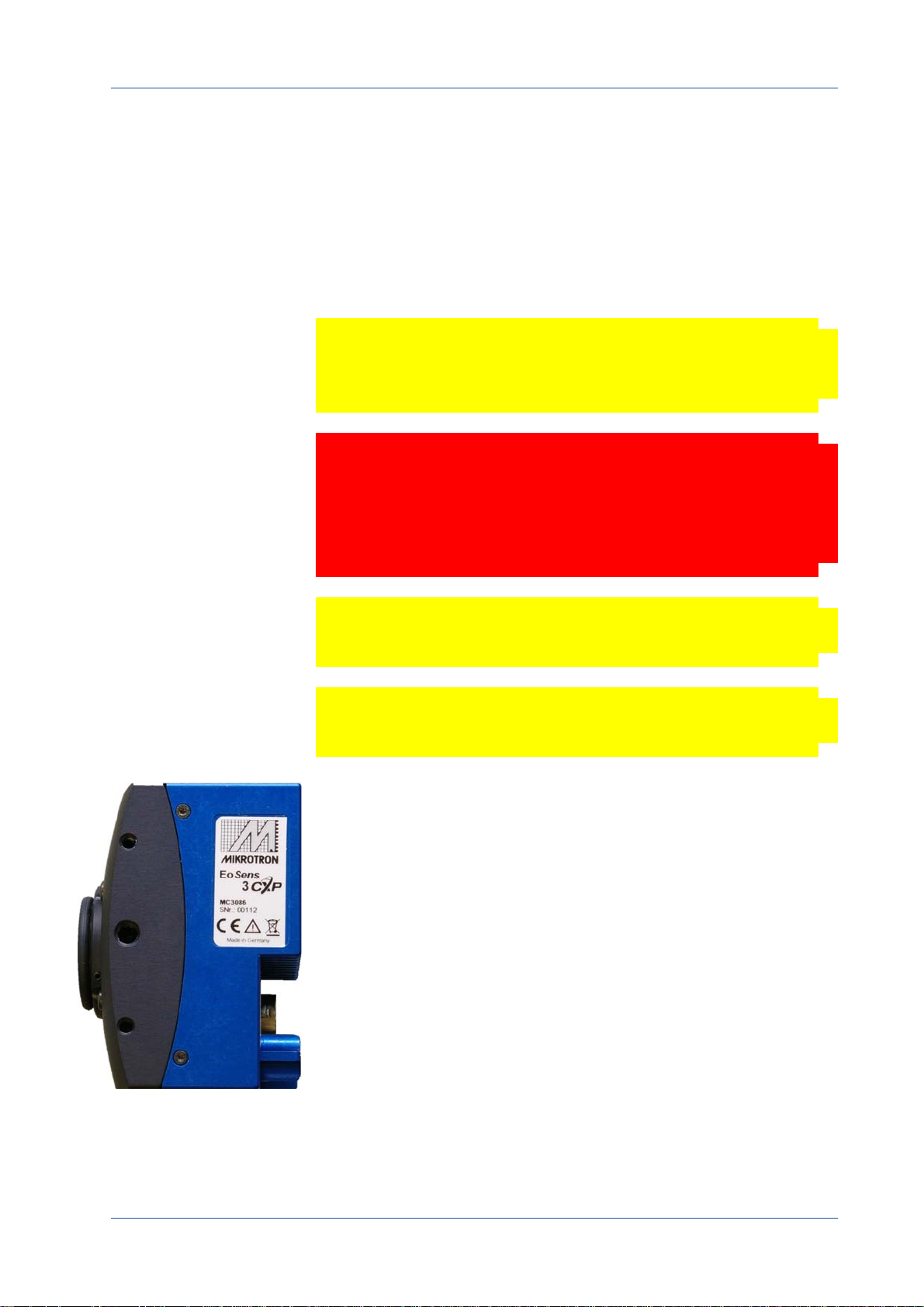
In case of warranty, please, make a note of the camera type and its
serial number.
You find all necessary information on the identification plate of the
camera.
Before sending back the camera, ask for a RMA (return merchandise
authorization) number and RMA form either by:
phone: +49 ‐ 89 ‐ 7263 4250 or
e‐mail:
service@mikrotron.de
Then send the camera back to your distributor. If no distributor is
available, send it back to MIKROTRON.
MIKROTRON GmbH 1 ‐ 5

EU Declaration of Conformity EU-Konformitätserklärung
MIKROTRON GmbH Phone: +49 (0)89 72634200
Landshuter Str. 20‐22 Fax: +49 (0)89 726342‐99
D‐85716 Unterschleissheim Mail: info@mikrotron.de
www.mikrotron.de
We herewith declare under our sole responsibility that the products mentioned below:
Hiermit erklären wir in alleiniger Verantwortung, dass die folgenden Produkte:
Product type: Camera
Produkt: Kamera
Models:
Modelle:
MC3082 and 3083, MC3086 and 3087
MC3082 and 3083, MC3086 and 3087
are in conformity with the following EU directives:
den folgenden EU‐Richtlinien entsprechen:
Title / Titel EU Directive
RoHS Directive on the Restriction of the Use of Certain
Hazardous Substances in Electrical and Electronic Equipment
RoHS‐Richtlinie zur Beschränkung der Verwendung bestimmter gefährlicher Stoffe
in Elektro‐ und Elektronikgeräten
Approximation of the laws of the Member States relating to electromagnetic com‐
patibility and repealing Directive 89/336/EEC
Angleichung der Rechtsvorschriften der Mitgliedstaaten über die elektromag‐
netische Verträglichkeit und zur Aufhebung der Richtlinie 89/336/EWG
2011/65/EU
2004/108/EC2014/30/EU
During conformity‐testing the following standards were consulted:
Die Konformitätsvermutung wurde nach folgenden Standards überprüft:
Title / Titel EU Standard
Information technology equipment ‐ Immunity characteristics ‐ Limits and meth‐
ods of measurement
EN55024:2011‐09
Einrichtungen der Informationstechnik – Störfestigkeitseigenschaften ‐
Grenzwerte und Prüfverfahren
Information technology equipment ‐ Radio disturbance characteristics ‐ Limits and
methods of measurement
EN55022:2011‐12
Einrichtungen der Informationstechnik – Funkstöreigenschaften ‐ Grenzwerte und
Messverfahren
MIKROTRON GmbH 1- 6

CHAPTER
2
Introduction
This chapter describes the camera in general, which means, it
informs about:
• the most important camera features and its sensor
• where it can be used
• what is part of the delivery
• system requirements

Overview
Introduction
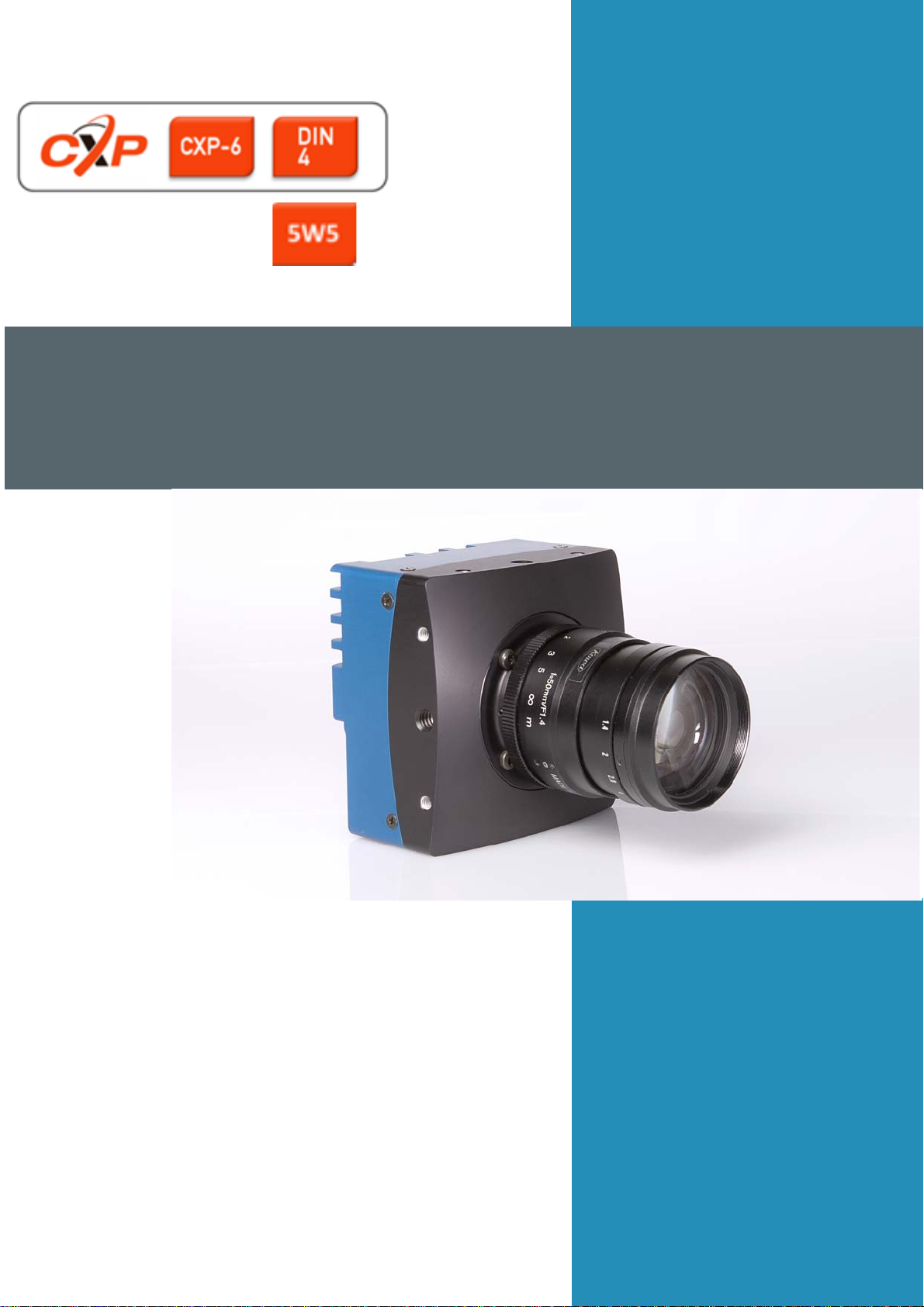
All cameras of the EoSens 3CXP family are CoaXPress compliant.
These high‐speed CMOS cameras come with a 3 Mega pixel sensor of
1696 (H) x 1710 (V). They are widely configurable and scalable to fit to
your needs and are available in monochrome and color (Bayer Filter).
The CoaXPress high speed interface technology allows transfer rates
of up to 6.25 Gbps. Your CXP camera supports CoaXPress Link Speeds
from 1.25 Gbps to 5.00 Gbps.
In addition they offer a very high frame rate of over 560 fps at full res‐
olution. By defining a Region of Interest (ROI) the frame rate can be
increased to several 1000ths of frames.
Another important feature of 3CXP cameras is the high photo sensi‐
tivity of 1270 V.m²/W.s at 600 nm with micro lens.
The camera electronic is enclosed in a compact and solid full metal
housing making it robust enough to comply with the requirements in
heavy industrial surroundings. Shielded coaxial cables as recom‐
mended by the CoaXPress standard will support this.
3CXP cameras can be equipped with standard C‐Mount or F‐Mount
lenses made for industrial purpose.
The most important features of the CXP camera are:
• 3 Mega pixel high speed CMOS sensor
• max. 560 fps
• more than 17,236 frames/s with reduced resolution
• 1” optical format (20.35 mm diagonal)
• active sensor area of 16.35 (H) x 12.10 (V) mm
2
•8 µm
pixels
•max. 3 ROI
• resolution of 1696 x 1710 pixels
• speed raise will be reached by lines
• 11V/lux.s@550nm
• 8 bit pixel output (256 gray levels)
• dynamic range of 60dB
• fill factor 0.4
• dual slope (up to 80 DB optical dynamic range)
• asynchronous trigger
• trigger IN; strobe OUT
MIKROTRON GmbH 2 ‐ 2

Introduction
• trigger frequency of 150 (one edge) and 300 kHz in AnyEdge
mode
• horizontal and vertical decimation
• FPN correction (5x5 matrix)
•CoaXPress link speeds: CXP1, CXP2, CXP3 and CXP5
• wide power supply range of 12 – 24V
This high‐speed camera comes with an electronically readable man‐
ual, describing all available GenICAM commands. For more informa‐
tion see "Configuring the Camera" on page 4‐4.
MIKROTRON GmbH 2 ‐ 3
Scope of Delivery
The following components are part of delivery. Please, check whether
the delivery is complete, before you start installing the camera:
Introduction
• Camera MC308x
•F‐Mount or C‐Mount lens adapter as ordered
• MIKROTRON’s Support CD with
– VCAM2 software
– GenICam XML file
– product documentation
Remark: In case you need a
firmware update, inform
MIKROTRON via mail:
info@mikrotron.de
Firmware can be updated remotely via a special updating software.
Optional Accessories
Lenses: To find lenses or other accessories, visit
www.mikrotron.de/en
Cables
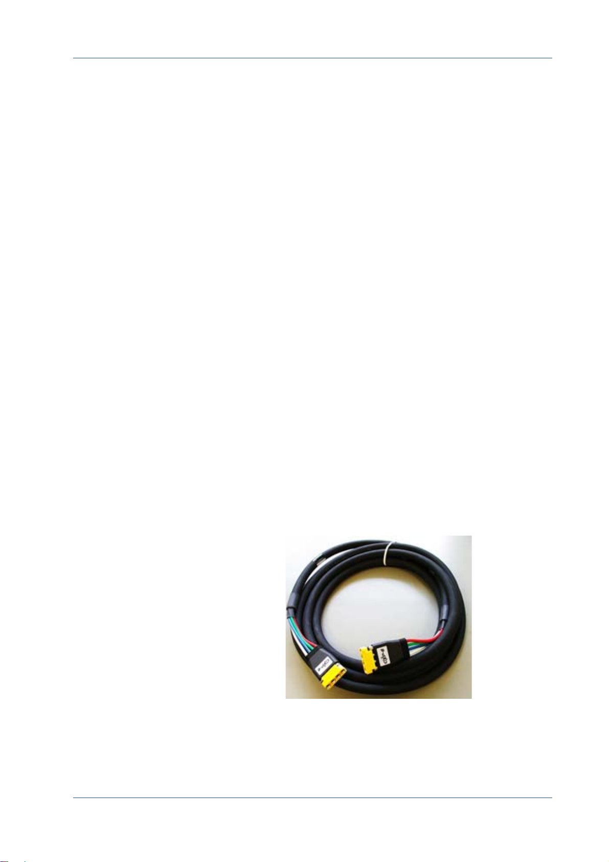
• The four bundle cable KKRDDINDINxx/6Gx4 with DIN 1.0/2.3
connector at both ends (4x) is available in lengths of 5, 10, 15,
or 20 m. It is used to connect the frame grabber and camera
when both are equipped with DIN 1.0/2.3 connectors.
Tip: The triangle on the con‐
nector indicates connection
number 1.
MIKROTRON GmbH 2 ‐ 4
Introduction
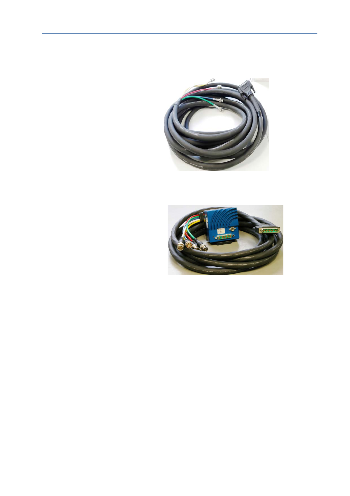
• The cable KKRDDINBNCxx/6Gx4 with DIN 1.0/2.3 at one end
and 4 BNC connectors at the other is available lengths of 5,
10, 15, 20 or 25m. It is used to connect a frame grabber with
BNC sockets with the camera.
• 5W5: there are several cables (KKRD5W5BNCxx) for 6 GHz
with a length of 5, 10, 15, 20 m or longer available. Please,
contact your sales representative
MIKROTRON GmbH 2 ‐ 5

Introduction
• Power Supply: If you do not use power over CXP, you need an
external power supply unit, e.g.:
– MC3086/MC3087: NTCAM132x (12 V/2.5 A) with 12 pin
Hirose connector and 5 m cable or
– MC3082/MC3083: NTCAM13xx with 6 pin Hirose connec‐
tor and 5/10 m cable
– MC3082/MC3083: NTCAM13xx with 6 pin Hirose connec‐
tor and a strobe output and 5/10 m cable
•F‐mount adapter
MIKROTRON GmbH 2 ‐ 6

System Requirements
In order to use the MC308x camera you need:
• an image processing system, e.g.: PC and operating system
according to the requirements of the frame grabber
• a completely installed frame grabber with device driver and
software
Introduction
Tip: Read more about frame
grabbers that were tested
with MIKROTRON cameras
in the Application Note
AN0036.
• CoaXPress cable with DIN 1.0/2.3 or 5W5 connector
• if wanted, an external power supply (NTCAM132x or
NTCAM13xx)
Note All cables, connectors and the frame grabber have to be
CoaXPress V1.1 compliant.
MIKROTRON GmbH 2 ‐ 7

CHAPTER
3
The 3CXP Camera
The chapter describes the camera in general which means:
• the camera types and its differences
• its operating temperature and additional cooling
• how to connect frame grabber and an external power sup‐
ply including pinning and internal circuit
• LED to verify the camera status
• correlation between transfer speed and resolution
• how to clean lens and sensor

Camera Description
3CXP cameras are available with 5W5 or DIN connector. All are
equipped with the same sensor providing a resolution of 2336 x 1728
pixels.
The sensor of the color camera is covered with a Bayer filter in order
to get the RGB information of each image pixel.
In addition, color cameras are equipped with an UV/IR cut filter. Light
with wavelengths between 370 and 670 nm will be transmitted.
These filters assure accurate color images.
There are four camera types available:
The 3CXP Camera
Type Data width
MC3082 8 bit m C‐/F‐mount CXP‐5 566 fps 5W5
MC3083 8 bit c C‐/F‐mount
MC3086 8 bit m C‐/F‐mount CXP‐5 566 fps DIN1.0/2.3
MC3087 8 bit c C‐/F‐mount CXP‐5 566 fps DIN1.0/2.3
Mono: m
Color: c
Lens Adapter Link speed
CXP‐5 566 fps 5W5
Max. fps@
2336x1728
Connector
MIKROTRON GmbH 3 ‐ 2

Operating Temperature
Despite of its high performance, the fan less CXP camera is compact
and works noiselessly. Supposed, the camera is mounted on mechan‐
ical parts, heat, generated during operation, will be dissipated by the
cooling fins at the rear of the camera and the mechanical parts.
Note The camera’s body temperature must not exceed 55°C.
In case of overheating, the camera will automatically be switched off
and the communication between camera and PC will be interrupted.
Wait until the camera has cooled down, then switch it on.
After a restart of the software the camera can be re‐initialized. Please,
take appropriate cooling measures as described below before operat‐
ing the camera again.
The 3CXP Camera
Additional Cooling
Tip: If the camera is e.g.
mounted on a sturdy alumi‐
num structure, not only
cooling is ensured but also a
stable optical path. In addi‐
tion, vibrations will be mini‐
mized within the entire
system.
Note The camera is not intended for use on an isolated mount‐
ing plate or in a closed housing where the temperature of
the camera will rise.
If the ambient temperature is constantly exceeding 40°C, additional
cooling will be required. This can be achieved by an
•air‐ or water‐cooling system or by
•air‐conditioned housings
MIKROTRON GmbH 3 ‐ 3
Interfaces of the Camera
1
2
3
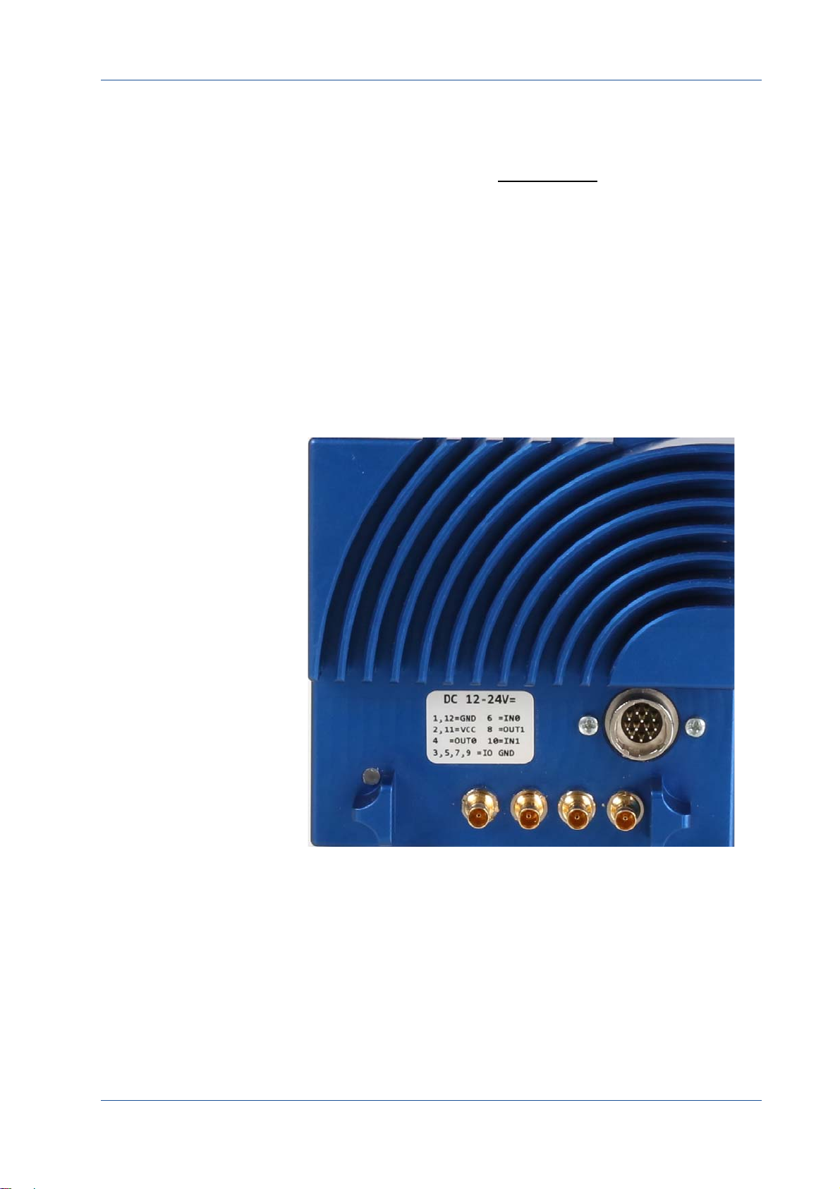
At the rear of the camera with DIN connector you find one:
1) status LED
in order to verify the operating status of the camera
2) CoaXPress DIN1.0/2.3 connector with four channels
which is used to connect the camera with a CoaXPress compli‐
ant frame grabber. It can supply the camera with power via
power over coax (PoC)
3) 12 pin Hirose power connector
which is used when an external power supply (12 ‐ 24V) and/
or an external trigger is connected
Remark: Before connec‐
ting an external trigger,
check the pinning of the
Hirose connector, descri‐
bed on page 3‐8. In addi‐
tion, take the trigger
settings into account. For
more information see
"Acquistion Control" on
page 5‐2.
The 3CXP Camera
Image 3‐1: CXP camera with DIN connector
MIKROTRON GmbH 3 ‐ 4
The 3CXP Camera
1
2
3
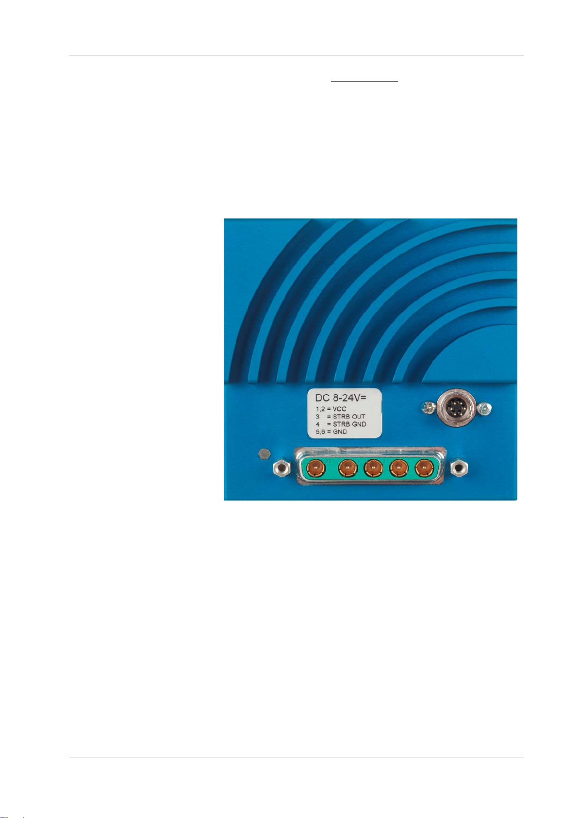
At the rear of the camera with 5W5 connector you find:
1) status LED
in order to verify the operating status of the camera
2) 5W5 connector is used to connect the camera via 4 lines with a
CoaXPress frame grabber and to supply the camera with power
(power‐over‐coax, so called PoC
3) 6 pin Hirose power connector
which is used when an external power supply (12 ‐ 24V) and/or
STRB
is connected
OUT
Image 3‐2: CXP camera with 5W5 connector
MIKROTRON GmbH 3 ‐ 5

Connecting a Frame Grabber
At the time being, the CoaXPress standard describes four connections
for data transmission between camera and frame grabber. The trans‐
mission speed of a 4CXP camera can either be set to 1.25, 2.5, 3.125, 5 or
6.25 Gbit/s.
and the transmission speed. The following table gives examples.
These values will only be reached if the signal quality meets the
requirements of the CXP‐1.1 specification.
Tip: The maximal cable
length depends also on the
quality of the cables. We
therefore recommend high‐
quality cables like the CXP
cables from MIKROTRON.
CXP‐Type
CXP‐1 1.25 up to 130
CXP‐2 2.5 up to 110
The 3CXP Camera
The possible cable length depends on the cable type used
Transmission speed
[Gbit/s]
Max. cable length
RG59 style [m]
CXP‐3 3.125 up to 100
CXP‐5 5 up to 60
4 x CXP‐5 4 x 5 Gbit/s = 20 Gbit/s up to 60
DIN Connector
In order to connect a CXP camera with a frame grabber you can use
any compatible CoaXPress cable with DIN connector. MIKROTRON
offers cables with the following connectors. For more information see
"Optional Accessories" on page 2‐4.
•DIN<‐>DIN
(cable KKRDDINDINxx/6Gx4)
•DIN<‐>BNC
(cable KKRDDINBNCxx/6Gx4)
WARNING! Please, carefully connect and release the socket with the
DIN1.1/2.3 connector. Connect them precisely to avoid
deformation of the connectors or other damages!
If connecting a frame grabber via DIN <‐> BNC, keep the order from
left to right when connecting one, two, or four BNC connectors.
MIKROTRON GmbH 3 ‐ 6

The 3CXP Camera
1
Remark: If you look at the
back of the camera, the left
DIN connector is the mas‐
ter connector number 1. It
always has to be con‐
nected.
All connections are hot‐pluggable.
No. of
Connections
1 1
2 1+2 (link)
4 1+2+3+4 (link)
On cables from MIKROTRON (KKRDDINDINxx/6Gx4), pin1 is marked with a
triangle on the connector housing.
Connector
combination
The assignment of the DIN‐cables KKRDDINDINxx/6Gx4 and KKRD‐
DINBNCxx/6Gx4 connector pins is as follows:
DIN connector
pin
1 (triangle) TX channel 0
2 TX channel 1
3 TX channel 2
4 TX channel 3
Frame grabber
5W5 Connector
In order to connect a MC4082/4083 camera with a frame grabber, use
MIKROTRON’s cable KKRD5W5BNC0x for 3 or 6 GHz and different
lengths.
WARNING! Please, carefully connect and release the socket with the
DIN1.1/2.3 connector. Connect them precisely to avoid
deformation of the connectors or other damages!
MIKROTRON GmbH 3 ‐ 7

The 3CXP Camera
If connecting a frame grabber via BNC, keep the order from right to
left.
Remark: The outer right
connector (1) is the master
connector and always has
to be connected.
All connections are hot‐pluggable. Connector 5 must not be used.
The assignment of the 5W5connector pins is as follow:
5W5 connector
pin
1 red TX channel 0
2 green TX channel 1
3 blue TX channel 2
4 white TX channel 3
5 yellow TX channel 0 (not yet
Cable color Function
Connecting an External Power Supply or I/O Signals
assigned, do not use!
In case you prefer an external DC power supply, connect it with the
Hirose connector at the rear of the camera.
WARNING! The power connector of the camera has to be connected
with a DC power supply providing 12 to 24 V DC. Con‐
necting a lower or higher supply voltage, an AC voltage,
reversal polarity or using wrong pins of the power con‐
nector may damage the camera and will void warranty!
MIKROTRON offers the power supply unit NTCAM132xx with cables of
5 or 10 meters. In case you assemble your own cable, pay attention to
the pinning described below.
Cameras with a DIN connector are equipped with a 12 pin and cam‐
eras with 5W5 connector with a 6 pin Hirose power connector.
MIKROTRON GmbH 3 ‐ 8
The 3CXP Camera
connected with:
pin 4
pin 6
pin 10
connected with pin 3 + 5
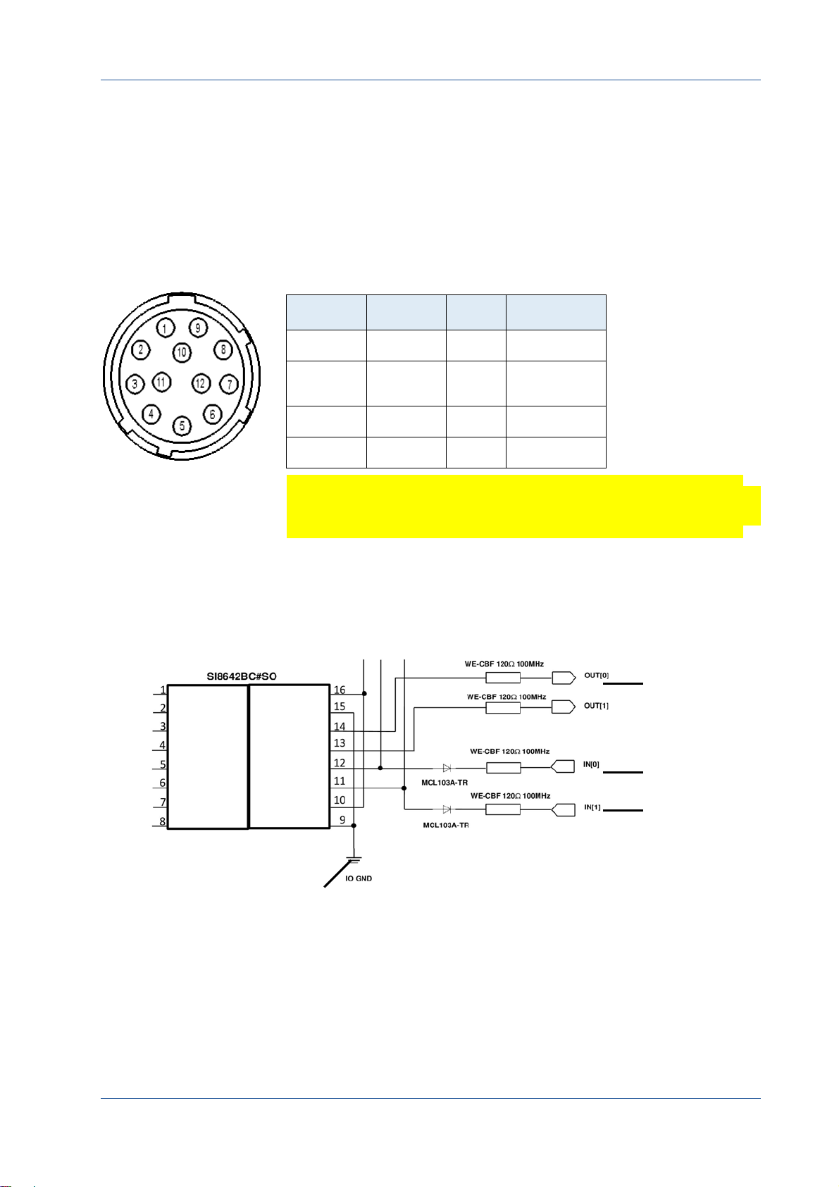
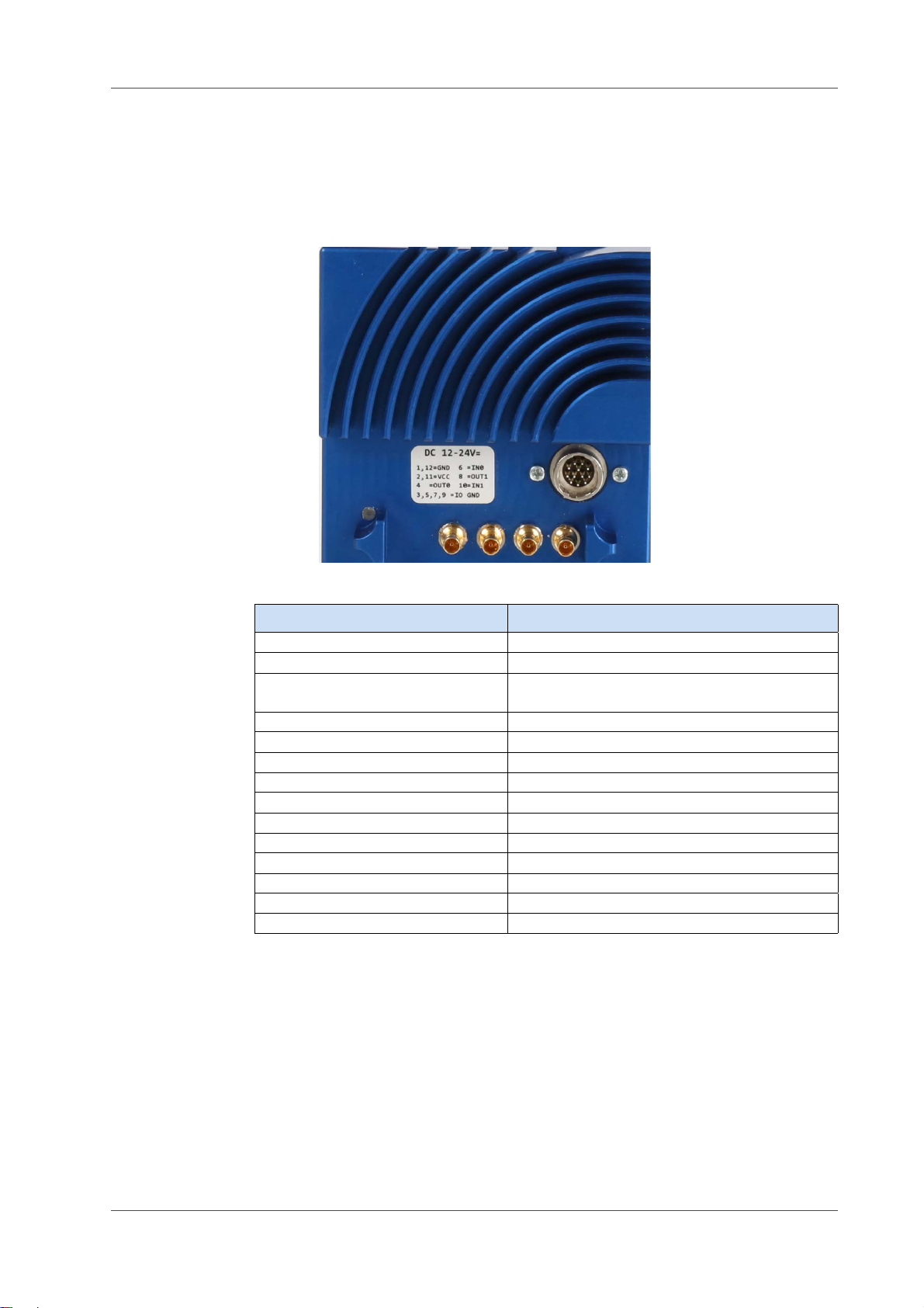
12 Pin Hirose Connector and I/O Signals
In case you prefer an external power supply for MC4086/4087, connect it
with the 12 pin Hirose connector (HR10A‐10R‐12PB (71)) at the back of the
camera. The DC power supply has to deliver 12 ‐ 24 V DC (7 W).
The 12 pin connector provides one strobe signal (OUT0) which is low during
exposure and two inputs for an external trigger.
Tabl e 3‐1: Pinning of the 12 pin power connector
Pin Signal Pin Signal
Remark: The I/O pins 7 and
8 (OUT[1]) are not in use.
1 + 12 GND 5 IO
2 + 11 VCC
(8 ‐ 24 V)
3 IO
4 OUT0 10 IN1
GND
6 IN0
9 IO
GND
GND
Note The I/O standard 3.3V LVTTL applies to all signal I/Os
(STRB + TRIG).
When connecting an external trigger, it might be helpful to know how
the OUT and IN pins are internally connected.
Image 3‐3: Internal circuit for IN and OUT pins
MIKROTRON GmbH 3 ‐ 9
The 3CXP Camera
connected
with STRB
OUT
connected
with GND
STRB
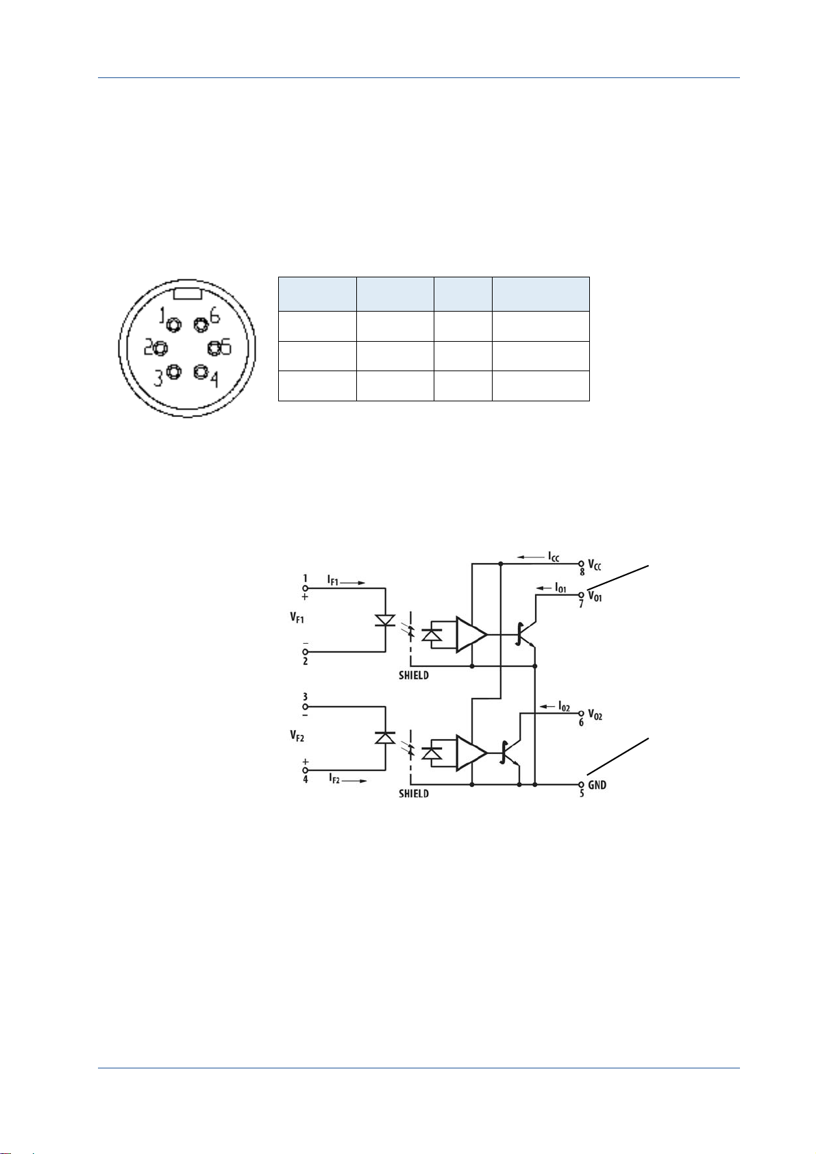
6 Pin Hirose and I/O Signals
The power connector of the cameras MC4082/MC4083 has to be con‐
nected via the 6‐pin Hirose connector (HR10A‐7P‐6S) with a DC supply
voltage between 12 and 24 V at a power consumption of 7W max.
The DC power supply unit is connected to a dedicated connector at
the back side of the camera. Please, take attention to the pin wiring of
the connector as described below.
Pin Signal Pin Signal
1 VCC 6 GND
2 VCC 5 GND
3 STRB
OUT
4 GND
STRB
The 6 pin connector provides a strobe signal (STRB
during exposure.
Internally, the STRB signal of pin 3 (STRB
and pin 4 (GND
) with pin 5 of the internal circuit.
STRB
) is connected with pin 7
OUT
) which is low
OUT
MIKROTRON GmbH 3 ‐ 10
Status LED
1
The 3CXP Camera
A multi‐color LED (1) indicates camera and CXP connection states
according to the CXP 1.1 standard.
Tabl e 3‐2: LED indications
LED State Indication
OFF no power
solid orange system is booting
slow pulse red powered, but nothing connected
(not applicable if PoC is used)
fast flash alternate green/orange connection detection in progress, PoC active
fast flash orange connection detection in progress, PoC not in use
slow flash alternate red/green device incompatible, PoC active
slow flash alternate red/orange device incompatible, PoC not in use
solid green device connected but no data being transferred
slow pulse orange device connected, waiting for event (e.g. trigger)
fast flash green device connected, data being transferred
slow flash alternate green/orange connection test packets being sent
red ‐ 500 ms pulse error during data transfer
slow flash alternate red/green/orange compliance test mode enabled
fast flash red system error
MIKROTRON GmbH 3 ‐ 11

Resolution and Speed
The table below shows the correlation between camera resolution
and the transmission speed for an 8‐bit image and the connections
from 1.25 to 6.25 Gbit/s.
The 3CXP Camera
Resolution
[Pixel]
H V 1.25 2.5 3.125 5 6.25
1024 1024 440 474 474 791 949
1280 720 479 674 674 1124 1349
640 480 1010 1010 1010 1684 2020
256 256 1887 1887 1887 3146 3775
Tip: Use our camera com‐
pare tool to calculate the
frame rate for a certain ROI
size.
www.mikrotron.de/cameracompare
Cleaning Sensor and Lens
If necessary, clean the window of the sensor and the lens with a dry
and soft lens‐cleaning tissue.
Frame rate [Gbit/s]
WARNING! Unplug the camera before you clean any parts!
In no case open the housing when cleaning the window
of the sensor.
WARNING! If there are coarse particles on the lens or the window of
the sensor, use a vacuum cleaner to remove them before
cleaning. Otherwise, the lens or sensor might be
scratched.
WARNING! Don't use tools that may harm the sensor/lens.
MIKROTRON GmbH 3 ‐ 12

CHAPTER
4
First Steps
In this chapter you learn
• how to connect the camera with the image processing sys‐
tem
• about initial settings the camera provides when being pow‐
ered‐up
• basics on the configuration of the camera via GenICam

Connect Camera and Image Processing System
CXP Camera
Cable DIN/DIN or DIN/BNC
Frame Grabber
Image Processing
System
Before you start, make sure that all components of the camera/host
chain like camera, connectors, cable and frame grabber as well as the
software are fully CoaXPress V1.1 compliant.
Step 1. Switch off the image processing system
Step 2. Connect the 5W5/DIN V1.1/2.3 cable with the camera
Step 3. Connect the other end of the cable with your CoaX‐
Press V1.1 compatible frame grabber
First Steps
Step 4. If an external power supply is needed, connect the
power supply NTCAM132x (12 ‐ 24 V) via the 12 pin
Hirose connector with the camera
Step 5. In case you want to connect an external trigger, take
the pinning into account. For more information see
"Connecting an External Power Supply or I/O Signals"
on page 3‐8.
Step 6. Unscrew the dust protection cover of the camera
Step 7. Mount the lens
MIKROTRON GmbH 4 ‐ 2

Power-up Profile
If the camera is powered‐up, the power‐up profile which is perma‐
nently stored in the non‐volatile memory of the camera, will be
loaded. This profile consists of a number of camera settings like sen‐
sor resolution and frame rate. It is used to bring the camera into a
defined operation mode.
First Steps
Step 8. If an external power supply is used, connect it with the
main supply
Step 9. Switch‐on the image processing system
Step 10. Check the LED of the camera to verify that the camera
is ready for use. (For more information see "Status
LED" on page 3‐11. )
Tip: The camera has NOT to
be configured by the host to
start operation. The power‐
up profile will deliver all
necessary values.
Serial number and firmware version are provided in the non‐volatile
memory of the camera too. Use the GenICam feature DeviceSerial‐
Number to read the serial number and the firmware revision. Read
the chapter Bootstrap Registers for more information.
If you need the serial number only, you find it on the identification
plate of the camera.
MIKROTRON GmbH 4 ‐ 3

Configuring the Camera
All MIKROTRON’s CXP cameras are compliant to the CoaXPress specifi‐
cation. CoaXPress standardizes down‐ and uplink protocols, inter‐
faces, cables, and connectors used by CoaXPress compliant cameras
and frame grabbers.
All our CXP cameras use GenICam, which is a standardized generic
programming interface. It is used to configure and control the CXP
camera and supports five main features:
1. camera configuration
2. frame acquisition
3. graphical user interface (GUI)
4. transfer of camera data but also time stamps, region of inter‐
est (ROI) and histogram data
First Steps
5. transfer of events like a trigger
GenICam for CXP cameras consists of four parts:
1. GenAPI
GenAPI is the application programming interface. It is used to
configure and control a camera. All features are written in an
XML file. The API is available for several operating systems.
2. Standard Features Naming Convention (SFNC)
SFNC provides standardized names and types for common
device features.
3. Pixel Format Naming Convention
PFNC is a pixel format naming convention.
4. GenTL
The GenTL transport layer is supported by CoaXPress compli‐
ant frame grabbers and cameras. It is used to transport cam‐
era data into the user application.
According to GenICam the camera uses registers for configuration. In
order to change a value, e.g. the exposure time, the hexadecimal
value has to be written into the camera register representing the
exposure time (e.g. 0x1100).
MIKROTRON GmbH 4 ‐ 4

Reading the XML File
All features of a CXP camera are described in the GenICam XML file.
This ASCII file is on the delivered DVD. Extensible Markup Language
(XML) is used to describe each feature as a XML feature knot.
Each knot consists at least, of the type of the feature (command,
string, integer,...), its access mode (R/W), a descriptive name (friendly
name), the corresponding register address, and a short description of
the feature in plain ASCII text. Some features have min. and max. val‐
ues or a default value.
Example:
<Command Name="AcquisitionStart">
<ToolTip>Starts the Acquisition of the device.</ToolTip>
<Description>Starts the Acquisition of the device.</Description>
<DisplayName>Acquisition Start</DisplayName>
<Visibility>Beginner</Visibility>
<pValue>AcquisitionStartReg</pValue>
<CommandValue>0</CommandValue>
</Command>
<IntReg Name="AcquisitionStartReg">
<Address>0x8204</Address>
<Length>4</Length>
<AccessMode>WO</AccessMode>
<pPort>Device</pPort>
<Endianess>BigEndian</Endianess>
</IntReg>
First Steps
Remark: All integer values
are interpreted as 32 bit
unsigned integers, if not
other mentioned. All
strings are NULL termi‐
nated and consist of 8 bit
characters.
The features in the XML file or your CXP camera are grouped accord‐
ing to their meaning. Available registers are:
• "Bootstrap Registers" on page 6‐2
• "Acquistion Control" on page 5‐2
•"Device Control" on page7‐1
•"Image Format Control" on page8‐1
• "User Set Control" on page 10‐1
• "Custom Features" on page 11‐1
• "Analog Control" on page 9‐1
The XML file can either be saved (compressed or uncompressed) in
the camera or saved as an external file on a local computer or a
remote host. The path (URL) of the file can be read from the camera
using the feature XmlUrlAddress.
MIKROTRON GmbH 4 ‐ 5

First Steps
Use the Software delivered by the frame grabber’s manufacturer to
configure camera and frame grabber. In case you use a frame grabber
from Active Silicon, MIKROTRON’s VCAM Software which is part of the
delivery, can be used alternatively.
Please, refer to www.emva.org/standards‐technology/genicam for
further details on the GenICam standard.
MIKROTRON GmbH 4 ‐ 6

CHAPTER
5
Acquisition Control
This chapter provides information on available settings to control
image acquisition and:
• configure the trigger settings
• control exposure
• set and read the (maximal) acquisition frame rate
• select a test image

Acquisition Control
Acquistion Control
The following commands allow to make settings required for image
acquisition and to control an external trigger. Settings can only be
changed if image acquisition is stopped.
Name Access Length [Bytes] Register Interface Page
AcquisitionMode R/W 4 Enumeration 5‐2
AcquisitionStart W 4 Command 5‐3
AcquisitionStop W 4 Command 5‐3
TriggerSelector R/W 4 Enumeration 5‐4
TriggerMode R/W 4 Enumeration 5‐4
TriggerSource R/W 4 Enumeration 5‐5
TriggerActivation R/W 4 Enumeration 5‐6
TriggerSoftware WO 4 Integer 5‐5
TestImageSelector R/W 4 Enumeration 5‐9
ExposureMode R/W 4 Enumeration 5‐7
ExposureTime R/W 4 Integer 5‐7
ExposureTimeMax R 4 Integer 5‐7
AcquisitionFrameRate R/W 4 Integer 5‐8
AcquisitionFrameRateMax R 4 Integer 5‐8
DualSlopeEnable R/W 4 Enumeration 5‐9
DualSlope R/W 4 Integer 5‐10
AcquisitionMode
This feature is used to set the device into a certain acquisition mode.
Access
Type
In
Out
Remark
read / write
enumeration
Continuous
selected mode
frame acquisition can be stopped with the feature
AcquisitionStop
the camera records continuously a sequence of
frames
MIKROTRON GmbH 5 ‐ 2

AcquisitionStart
Acquisition Control
This feature enables the device to send sampled images to the host.
AcquisitionStop
Access
Type
In
Out
Remark
write
command
0x00000001
—
AcquisitionMode defines how frames will be acquired
This feature stops acquiring frames after the acquisition of the cur‐
rent frame has been completed.
Access
Type
In
Out
write
command
x00000001
—
MIKROTRON GmbH 5 ‐ 3

TriggerSelector
Acquisition Control
This feature is used to select the type of trigger to be configured.
TriggerMode
Access
Type
In
Out
read / write
enumeration
FrameStart the camera will take one picture per
trigger signal
trigger selector type
Remark
This feature activates or deactivates the trigger type selected by the
feature TriggerSelector.
Access
Type
In
read / write
enumeration
ON
enables the selected trigger type; the camera waits for a
trigger signal before acquiring a frame. The trigger sig‐
nal can be a signal from the frame grabber, the 12‐pin
Hirose connector input, or a software trigger initiated
by a software command. The trigger source has to be
set in the feature TriggerSource. In trigger mode, the
frame rate of the camera depends on the frequency of
the trigger signals
OFF
disables the selected trigger type; all trigger signals will
be ignored. The camera is set into the current acquisi‐
tion mode
Out
Remark
MIKROTRON GmbH 5 ‐ 4
active mode
If a trigger is active, ExposureMode defines whether the expo‐
sure of an image is defined by the feature ExposureTime (fixed
exposure time) or by the duration of the trigger signal itself
(variable exposure time). The settings in ExposureMode will only
become effective if triggered mode is ON.

TriggerSource
Acquisition Control
This feature defines the source of the trigger signal.
Access
Type
In
Out
Remark
read / write
enumeration
Line0
CXP cameras with DIN connector offer one trig‐
ger input with two physical lines via the 12 pin
Hirose connector (see page 3‐6); the trigger sig‐
nal can either be sent via line 0 or line 1
Line1
CXP cameras with DIN connector offer one trig‐
ger input with two lines via the 12 pin Hirose
connector; the trigger signal can either be sent
via line 0 or line 1
Software
CXPTrigger
active source
Only one trigger source can be active.
if TriggerSoftware is set, the trigger will be gener‐
ated by the software using the feature Trigger‐
Software; no external (hardware) trigger signal is
needed
if CXPTrigger is set, the camera will wait for an
external trigger signal from the frame grabber
before acquiring another frame; exposure time
for the next image is the time defined in the fea‐
ture ExposureTime
TriggerSoftware
Tip: When using Trigger‐
Software, the exposure time
of the next frame cannot be
defined by TriggerWidth of
the feature ExposureMode.
Instead, it has to be defined
by the feature Exposure‐
Time.
This feature generates an internal trigger.
Access
Type
In
Out
Remark
write
command
0x00000001
—
In order to generate a software trigger signal, “Software” has to
be set in TriggerSource.
MIKROTRON GmbH 5 ‐ 5

TriggerActivation
Acquisition Control
Tip: If AnyEdge is selected, a
fixed exposure time (Expo‐
sureMode = Timed) has to
be set.
This feature defines the activation mode for a trigger signal defined in
TriggerSele ctor.
Access
Type
In
Out
Remark
read / write
enumeration
RisingEdge
Falling Edge
Any Edge
selected activator
Using the activator AnyEdge doubles the maximal trigger fre‐
quency.
camera will start to acquire frames on the arrival
of a CXP 'trigger rising edge' trigger packet; this
activator expects a subsequent 'trigger falling
edge' trigger packet to finish the trigger
sequence
camera will start to acquire frames on the arrival
of a CXP 'trigger falling edge' trigger packet; this
activator expects a subsequent 'trigger rising
edge' trigger packet to finish the trigger
sequence
camera will start to acquire frames on the arrival
of a CXP 'trigger falling edge' as well as a 'trigger
rising edge' trigger packet
Tip: The best way to find the
appropriate value for the
debounce period is to mea‐
sured it with an oscillo‐
scope.
It allows e.g. to compare the number of frames transferred to the
frame grabber with the number of triggers. In TriggerDebouncer the
debounce period is defined. This period starts with the occurrence of
a trigger edge. Within the debounce period, a new trigger signal will
be ignored. Debouncing might e.g. be necessary if the trigger signal
jitters.
MIKROTRON GmbH 5 ‐ 6

ExposureMode
Acquisition Control
This feature sets the operation mode of the shutter. It defines how
long a picture will be exposed if TriggerMode is activated.
ExposureTime
Access
Type
In
Out
Remark
read / write
enumeration
Timed
Trigger
set exposure mode
ExposureMode is enabled in trigger mode only.
If you choose AnyEdge in TriggerActivator, Timed has to be set.
exposure time is defined in the feature
ExposureTime; frame rate is defined in the fea‐
ture AcquisitionFrameRate.
width of the current trigger signal pulse is used
Width
to control the exposure time; if TriggerActivation
is set to RisingEdge, it will be the time the trigger
stays high; if TriggerActivation is set to Falling
Edge it will last as long as the trigger stays low.
If the exposure mode is set to Timed or no hardware trigger is
defined, this feature allows to define the duration of exposure [µs].
ExposureTimeMax
Access
Type
In
Out
read / write
unsigned integer
1 … ExposureTimeMax
exposure time
This feature returns the highest possible exposure time for the cur‐
rent camera settings in [µs].
Access
Type
In
Out
Remark
read
unsigned integer
—
max. exposure time
The exposure time depends on the current frame rate settings.
MIKROTRON GmbH 5 ‐ 7

AcquisitionFrameRate
This feature defines the acquisition rate in [Hz] when TriggerMode is OFF.
Acquisition Control
Access
Type
In
Out
Remark
Tip: If TriggerMode = ON,
AcquisitionFrameRate will
be disabled.
AcquisitionFrameRateMax
This feature returns the highest possible frame rate in [Hz].
Access
Type
In
Out
Remark
read / write
unsigned integer
>10... AcquisitionFrameRateMax
AcquisitionFrameRate
incremented by 1; min. 10
read
unsigned integer
—
max. frame rate
The max. frame rate depends on the defined frame size, the
used link speed, and the number of CoaXPress lines used for
image streaming.
MIKROTRON GmbH 5 ‐ 8

TestImageSelector
Acquisition Control
This feature selects the type of test image sent by the camera.
DualSlopeEnable
Access
Type
In
Out
Remark
read/write
enumeration
OFF
TestImageSelector is disabled
GreyHorizontal
GreyDiagonal
HorizontalRamp
current test image selection
A connection reset sets the camera into normal operation mode.
camera will send a test image that shows
Ramp
vertically oriented gray scale bars moving
into horizontal direction on the screen
camera will send a test image that shows
diagonally oriented gray scale bars moving
on the screen into horizontal direction
This feature enables/disables the dual slope function.
Access
Type
In
Out
Remark
read/write
enumeration
—
length of 4 Bytes
OFF
DualSlope is disabled
ON
DualSlope is enabled
MIKROTRON GmbH 5 ‐ 9

DualSlope
Acquisition Control
This feature allows adjusting overexposed areas of an image.
Access
Type
In
Out
Remark
read / write
integer
0 ... 100%
set percentage
dual slope value of the exposure time in percent
As the gray value dynamic of the camera amounts to 8 bit (pixel val‐
ues from 0 (black) to 255 (white)) image parts will be overexposed if
pixel values exceed the value 255.
Overexposuring is difficult to compensate by reducing the exposure
time or decreasing brightness. The gray value represents the number
of photons (brightness) captured by the sensor. The exposure time
defines the period the sensor will be photosensitive. Reducing the
exposure time will result in underexposed dark areas. Decreasing
brightness will change all pixel values and dark areas might become
too dark.
A better solution to compensate overexposuring of very bright parts
is to use the dual slope feature in order to extend the dynamic range.
Example: The four blue lines in the diagram below represent ana‐
log signals of four different pixels which decrease as a result of
exposure. The slope is determined by the amount of light (the
more light, the steeper the slope). If a pixel reaches the saturation
MIKROTRON GmbH 5 ‐ 10

Acquisition Control
level, the analog value will no longer change despite of further
exposure.
Without dual slope, pixels p3 and p4 are saturated before the expo‐
sure time has elapsed. As a result they will be overexposed.
Supposed, the dual slope value is set to 80 percent, and exposure
time amounts to 1 µs. In this case the analog signal of p3 and p4 will
be reset to the 2nd reset level after 80 percent of the exposure time
has been elapsed. The signals of p3 and p4 start decreasing with the
same slope as before but will not be saturated at read out time.
MIKROTRON GmbH 5 ‐ 11

CHAPTER
6
Bootstrap CoaXPress
The chapter provides information on:
• bootstrap registers which are mainly used to deliver infor‐
mation about the camera in order to allow a communica‐
tion between frame grabber and camera

Bootstrap Registers
CoaXPress compliant devices have to support a number of bootstrap
registers. In contrast to other CXP camera features each bootstrap
register is assigned to a fixed camera address as it is defined in the
CoaXPress specification.
Bootstrap registers are defined for device information and allow
frame grabbers to establish and maintain the connection between
host and camera in a standardized way. Usually, the connection
between camera and frame grabber is running in the background.
Bootstrap CoaXPress
Name Address Access
Standard 0x00000000 R 4 Integer 6‐3
Revision 0x00000004 R 4 Integer 6‐3
XmlManifestSize 0x00000008 R 4 Integer 6‐4
XmlManifestSelector 0x0000000C R/W 4 Integer 6‐4
XmlVersion 0x00000010 R 4 Integer 6‐4
XmlSchemeVersion 0x00000014 R 4 Integer 6‐5
XmlUrlAddress 0x00000018 R 4 Integer 6‐6
Iidc2Address 0x0000001C R 4 Integer 6‐5
DeviceVendorName 0x00002000 R 32 String 6‐6
DeviceModelName 0x00002020 R 32 String 6‐7
DeviceManufacturerInfo 0x00002040 R 48 String 6‐7
DeviceVersion 0x00002070 R 32 String 6‐8
DeviceSerialNumber 0x000020B0 R 16 String 6‐8
DeviceUserID 0x000020C0 R/W 16 String 6‐9
WidthAddress 0x00003000 R/W 4 Integer 6‐9
HeigthAddress 0x00003004 R/W 4 Integer 6‐9
AcquisitionModeAddress 0x00003008 R/W 4 Integer 6‐9
AcquistionStartAddress 0x0000300C R/W 4 Integer 6‐9
AcquistionStopAddress 0x00003010 R/W 4 Integer 6‐9
PixelFormatAddress 0x00003014 R/W 4 Integer 6‐9
DeviceTapGeometrieAddress 0x00003018 R/W 4 Integer 6‐9
Image1StreamIDAddress 0x0000301C R/W 4 Integer 6‐9
ConnectionReset 0x00004000 W/(R) 4 Integer 6‐10
DeviceConnectionID 0x00004004 R 4 Integer 6‐10
MasterHostConnectionID 0x00004008 R/W 4 Integer 6‐10
ControlPacketSizeMax 0x0000400C R 4 Integer 6‐11
StreamPacketSizeMax 0x00004010 R/W 4 Integer 6‐11
Length
[Bytes]
Register
interface
Page
MIKROTRON GmbH 6 ‐ 2

Bootstrap CoaXPress
Name Address Access
ConnectionConfig 0x00004014 R/W 4 Enumerate 6‐12
ConnectionConfigDefault 0x00004018 R 4 Integer 6‐12
TestMode 0x0000401C R/W 4 Integer 6‐13
TestErrorCountSelector 0x00004020 R/W 4 Integer 6‐13
TestErrorCount 0x00004024 R/W 4 Integer 6‐14
TestPacketCountTx 0x00004028 R/W 8 Integer 6‐14
TestPacketCountRx 0x00004030 R/W 8 Integer 6‐15
HsUpConnection 0x0000403C R 4 Integer 6‐15
Start of manufacturer specific
register space
Standard
Length
[Bytes]
0x00006000 — — — 6‐9
Register
Interface
Page
This register provides a magic number indicating that the device
implements the CoaXPress standard.
Access
Type
In
Out
Remark
read
unsigned integer
—
0xC0A79AE5
The magic number is an approximation of CoaXPress.
Revision
This register provides the revision of the CoaXPress specification
implemented by this device.
Access
Type
In
Out
Remark
read
unsigned integer
—
bits
31 ‐ 16
15 ‐ 00
E.g. devices compliant to revision 1.1 of the specification shall
return the value 0x00010001.
major revision
minor revision
MIKROTRON GmbH 6 ‐ 3

XmlManifestSize
Bootstrap CoaXPress
This register returns the number of available XML manifests. At least
one manifest must be available.
XmlManifestSelector
Access
Type
In
Out
read
unsigned integer
—
1
This register selects the required XML manifest registers. It holds a
number between zero and XmlManifestSize – 1.
Access
Type
In
Out
Remark
read / write
unsigned integer
0 … XmlManifestSize‐1
0 … XmlManifestSize‐1
A connection reset sets the value to 0x00000000.
XmlVersion
This register provides the version number for the XML file given in the
manifest referenced by the register XmlManifestSelector.
Access
Type
In
Out
Remark
read
unsigned integer
—
bits
31 ‐ 24
23 ‐ 16
—
reserved; shall be 0
SchemaMajorVersion;
major version number of the XML file
15 ‐ 8
SchemaMinorVersion;
minor version number of the XML file
7 ‐ 0
SchemaSubMinorVersion; sub‐minor version num‐
ber of the XML file
MIKROTRON GmbH 6 ‐ 4

XmlSchemeVersion
Bootstrap CoaXPress
This register provides the GenICam schema version for the XML file
given in the manifest referenced by the register XmlManifestSelector.
Iidc2Address
Access
Type
In
Out
read
unsigned integer
—
bits
31 ‐ 24
23 ‐ 16
reserved; shall be 0
SchemaMajorVersion;
major version number of the schema used by the
XML file
15 ‐ 8
SchemaMinorVersion
minor version number of the schema used by the
XML file
7 ‐ 0
SchemaSubMinorVersion
sub‐minor version number of the schema used by
the XML file
This feature is meant for devices supporting the IIDC2 protocol (sec‐
tion 2.2 ref. 6) and will provide the starting address of the IIDC2 regis‐
ter space.
Access
Type
In
Out
Remark
read
unsigned integer
—
0x00000000
not supported
MIKROTRON GmbH 6 ‐ 5

XmlUrlAddress
Bootstrap CoaXPress
This register indicates the start of the URL string referenced by the
register XmlManifestSelector.
Access
Type
In
Out
Remarks
read
unsigned integer
—
register address
Reading the returned register returns the name, register
address, and the length of the GenICam XML file stored in the
flash memory of the camera. The format of the address string of
the following fields is:
Local
indicates the XML file is stored in the non‐volatile
memory in the device
<Filename>
<Extension>
<Address>
<Length>
Example:
“Local:Mikrotron_GmbH_MC258xS11 _Rev1_15_0.xml;
8001000;16C34?SchemaVersion=1.1.0”
indicates a GenICam XML file in the flash memory of the camera.
The file can be read starting at address 8001000 and has a length
of 16C34 Bytes.
MIKROTRON does not support strings that reference a XML file
located on the vendors homepage.
name of the XML file
xml: uncompressed XML file
zip: compressed ZIP file
address of the file in the device memory map,
given in hexadecimal notation without the first
to characters “0x”
length of the file in Bytes, given in hexadecimal
without the first to characters “0x”
DeviceVendorName
This register provides the name of the manufacturer of the device as a string.
Access
Type
In
Out
Remark
MIKROTRON GmbH 6 ‐ 6
read
string [0...32]
—
vendor name
Example: MIKROTRON GmbH

DeviceModelName
Bootstrap CoaXPress
This register provides the model name of the device as a string.
Access
Type
In
Out
Remark
DeviceManufacturerInfo
This register provides extended manufacturer‐specific information
about the device as a string.
Access
Type
In
Out
Remark
read
string[0...32]
—
model name
Example: MC2586
read
string[0...48]
—
manufacturer information
Example: MIKROTRON GmbH
MIKROTRON GmbH 6 ‐ 7

DeviceVersion
Bootstrap CoaXPress
This register provides the version of the camera hardware as a string.
Access
Type
In
Out
Remark
read
string[0...32]
—
device version string including the hardware, microcontroller soft‐
ware and FPGA version
The firmware version consists of the microcontroller version plus
the FPGA version (V00.25.002F00.33.787). The format of the ver‐
sion string (byte numbers from left to right) in detail:
byte no.:
11 ‐ 12
14 ‐ 15
17 ‐ 19
21 ‐ 22
24 ‐ 25
27 ‐ 29
hardware tag
0
hardware version major number
1 ‐ 2
3
hardware version minor number
4 ‐ 5
6
hardware version sub minor number
7 ‐ 9
microcontroller tag
10
mc major number
13
mc minor number
16
mc sub minor number
FPGA tag
20
FPGA version major number
23
FPGA version minor number
26
FPGA version sub minor number
e.g.:
H
03
.
04
.
000
V
00
.
25
.
002
F
00
.
33
.
787
DeviceSerialNumber
This register provides the serial number for the device as a NULL‐terminated
string
.
Access
Type
In
Out
Remark
MIKROTRON GmbH 6 ‐ 8
read
string[0...16]
—
serial number of the camera
Example: 000000000000157

DeviceUserID
Bootstrap CoaXPress
This register provides a user‐programmable identifier for the camera
as a string.
Access
Type
In
Out
Remark
read/write
string[0...16]
user ID
user ID
The User ID can be freely defined by the user.
It will be saved in the flash memory of the camera. As a result, it
will be preserved if the camera is switched off.
Manufacturer-specific Addresses
The following registers provide the address in the manufacturer‐spe‐
cific register space of the use‐case feature with the corresponding
name. These registers have a length of 4 bit and are read‐only regis‐
ters.
WidthAddress
HeightAddress
AcquisitionModeAddress
AcquisitionStartAddress
AcquisitionStopAddress
PixelFormatAddress
DeviceTapGeometryAddress
Image1StreamIAddress
manufacturer‐specific address of Width
manufacturer‐specific address of Height
manufacturer‐specific address of AcquisitionMode
manufacturer‐specific address of AcquistionStart
manufacturer‐specific address of AcquistionStop
manufacturer‐specific address of PixelFormat
manufacturer‐specific address of DeviceTapGeometry
manufacturer‐specific address of Image1StreamID
Manufacturer‐specific addresses allow non‐GenICam applications or
black‐box format converters, to support the standard use‐case and
allow continuous acquisition and display of images.
MIKROTRON GmbH 6 ‐ 9

DeviceConnectionID
Bootstrap CoaXPress
This register provides the ID of the device connection via which this
register is read.
ConnectionReset
Access
Type
In
Out
Remark
Writing 0x00000001 into this register will reset the connection of the device.
Access
Type
In
Out
Remark
read
unsigned integer
—
connection ID
A connection ID of zero means that the connection is a master
connection. This is a static register, but with a different value
depending from which connection it is read.
read / write
unsigned integer
0x00000001
0x00000000
A link reset will stop a running image acquisition.
A connection reset command via the master connection (con‐
nection 0) will reset a connection and activate its discovery con‐
nection configuration within 200 ms. The camera resets the
register to 0x00000000 when it has activated its discovery con‐
nection configuration. Writing by the host should be regarded as
“fire and forget” without waiting for acknowledgment.
In general it is not possible to read this register while it has the
value 0x00000001.
MasterHostConnectionID
This register holds the host connection ID of the host connected to
the device master connection.
Access
Type
In
Out
Remark
MIKROTRON GmbH 6 ‐ 10
read/write
unsigned integer
host link ID
host link ID
The value 0x00000000 is reserved to indicate an unknown Host
ID. All writings to device extension connection will be ignored.

ControlPacketSizeMax
This register provides the maximum control packet size the host can
read from the device or write to the device. The size is defined in
Bytes and will be a multiple of 4 Bytes. The defined size is that of the
entire packet, not only the payload.
Bootstrap CoaXPress
Access
Type
In
Out
Remark
StreamPacketSizeMax
This register holds the maximum stream packet size the host can
accept. The size is defined in Bytes and will be a multiple of 4 Bytes.
The defined size is that of the entire packet, not only the payload.
Access
Type
In
Out
Remark
read
unsigned integer
—
control packet size in multiples of 4 Bytes
the control packet size is at least 128 Bytes
read / write
unsigned integer
stream packet data size in multiples of 4 Bytes
stream packet data size in multiples of 4 Bytes
The device can use any packet size it wants to up to this size.
A connection reset sets the value to 0x00000000.
MIKROTRON GmbH 6 ‐ 11

ConnectionConfig
Bootstrap CoaXPress
This register holds a valid combination of the device link speed and
the number of active down connections. Writing into this register sets
the connection speeds on the specified connections.
Access
Type
In
Out
read / write
enumeration
connection configuration example (read the electronically read‐
able manual for further information):
CONNECTION1SPEED3125
CONNECTION2SPEED3125
CONNECTION4SPEED3125
CONNECTION1SPEED5000
CONNECTION2SPEED5000
CONNECTION4SPEED5000
CONNECTION1SPEED6250
CONNECTION2SPEED6250
CONNECTION4SPEED6250
connection configuration
one connection of 3.125 Gbps per
connection
two connections of 3.125 Gbps per
connection
four connections of 3.125 Gbps per
connection (default)
one connection of 5.000 Gbps per
connection
two connections of 5.000 Gbps per
connection
four connections of 5.000 Gbps per
connection
one connection of 6.250 Gbps per
connection
two connections of 6.250 Gbps per
connection
four connections of 6.250 Gbps per
connection
ConnectionConfigDefault
This register provides the value of the ConnectionConfig register that
allows the Device to operate in default mode. This feature is used to
start the camera with the default configuration that is stored in the
custom profiles.
Access
Type
In
Out
Remark
MIKROTRON GmbH 6 ‐ 12
read
unsigned integer
—
0x00000000

TestMode
Bootstrap CoaXPress
Writing the value 0x00000001 into this register enables a test packet
transmission from the camera to the host.
Access
Type
In
Out
Remark
TestErrorCountSelector
This register selects the required test count [TestErrorCount] register.
It holds a valid device connection ID 0 … n‐1, or n for the optional
high‐speed up‐connection.
Access
Type
In
Out
Remark
read / write
integer
0x00000000
0x00000001
same as above
A connection reset sets the value to 0x00000000. If the value is
changed from 0x00000001 to 0x00000000, the device will com‐
plete the packet of 1024 test words currently being transmitted.
read / write
unsigned integer
0x00000000...0x00000003
0x00000000...0x00000003
A connection reset sets the value to 0x00000000.
normal operation
sending test packets to host
MIKROTRON GmbH 6 ‐ 13

TestErrorCount
Bootstrap CoaXPress
This register provides the current connection error count for the con‐
nection referred to by the register TestErrorCountSelector.
TestPacketCountTx
Access
Type
In
Out
Remark
read / write
unsigned integer
0x00000000
error count
Writing 0x00000000 to this register resets the error count for
the connector referred to by the register TestErrorCountSelector
to zero.
A connection reset sets all connection test counters to zero. The
error count is the number of incorrect words that have been
received in test packets.
This register provides the current transmitted connection test packet
count for the connection referred to by the register TestErrorCountSe‐
lector.
Access
Type
In
Out
Remark
read / write
integer
0x0000000000000000
packet count
Writing 0x0000000000000000 into this register will reset to zero
the transmitted connection packet count for the connection
referred to by the register TestErrorCountSelector. A connection
reset sets all connection test counters to zero.
MIKROTRON GmbH 6 ‐ 14

TestPacketCountRx
Bootstrap CoaXPress
This register provides the currently received connection test packet count for
the connection referred to by the register
TestErrorCountSelector.
HsUpConnection
Access
Type
In
Out
Remark
read / write
integer
0x0000000000000000
packet count
Writing 0x0000000000000000 to this register shall reset to zero
the received connection packet count for the connection
referred to by register TestErrorCountSelector. A connection
reset sets all connection test counters to zero.
This register indicates whether the optional high speed up‐connec‐
tion is supported or not.
Access
Type
In
Out
Remark
read
integer
bits 1 ‐ 30: reserved; shall be 0
ON = 1
OFF = 0
0 if high speed up‐connection is OFF
1 if high speed up‐connection is ON
This feature is currently not supported.
MIKROTRON GmbH 6 ‐ 15

CHAPTER
7
Device Control
The chapter provides the only command on device control which is
used to reset the camera.

Introduction
DeviceReset
Device Control
There is only one command to reset the camera.
This feature resets the device into power‐up state.
Access
Type
In
Out
Remark
write
unsigned integer
0x00000001
—
length of 4 Bytes
MIKROTRON GmbH 7 ‐ 2

CHAPTER
8
Image Format Control
The chapter provides information on the image format control. You
learn how to
• define the size and offset of a ROI
• read the size of the sensor
• read the max. height and width of an image
• read/write the pixel format
• read the TapGeometry
• read the streamID
• read the camera type (line or area scan)

Introduction
Image Format Control
These commands allow to set the size of the image, the so called
region of interest (ROI). A ROI ‐ like the red field in the figure below ‐
defines the part of an image to be scanned. It is defined by its Width,
Heigth, OffsetX and OffsetY.
Name Access
Width R/W 4 Integer 8‐3
Height R/W 4 Integer 8‐3
OffsetX R/W 4 Integer 8‐3
OffsetY R/W 4 Integer 8‐4
SensorWidth R 4 Integer 8‐4
SensorHeight R 4 Integer 8‐4
WidthMax R 4 Integer 8‐5
HeightMax R 4 Integer 8‐5
PixelFormat R/W 4 Enumeration 8‐6
TapGeometry R 4 Enumeration 8‐6
Image1StreamID R 4 Integer 8‐7
DeviceScanType R 4 Enumeration 8‐7
Length
[Bytes]
Register
Interface
Page
MIKROTRON GmbH 8 ‐ 2

Width
Image Format Control
This feature provides the image width in pixels.
Height
Access
Type
In
Out
Remark
This feature provides the image height in lines.
Access
Type
In
Out
Remark
read / write
unsigned integer
128 … WidthMax
image width
the maximum value of this feature equals to SensorWidth; the
image width has to be incremented by 64 pixels
read / write
unsigned integer
1 … HeightMax
image height
the maximum value of this feature equals to SensorHeight; the
image height has to be incremented by 1 line
OffsetX
Horizontal offset from the origin to the region of interest (in pixels).
Access
Type
In
Out
Remark
read / write
unsigned integer
0 … OffsetXMax
horizontal offset
the maximal offset equals to SensorWidth. The offset has to be
incremented by 64 pixels.
MIKROTRON GmbH 8 ‐ 3

OffsetY
Image Format Control
Vertical offset from the origin to the region of interest (in lines).
SensorWidth
Access
Type
In
Out
Remark
read / write
unsigned integer
0 … OffsetYMax
vertical offset
The maximal offset equals to SensorHeight. The offset has to be
incremented by 1 line.
Effective width of the sensor in pixels.
Access
Type
In
Out
read only
unsigned integer
—
sensor width
SensorHeight
Effective height of the sensor in pixels.
Access
Type
In
Out
read only
unsigned integer
—
sensor height
MIKROTRON GmbH 8 ‐ 4

WidthMax
Image Format Control
Maximum width of the image in pixels.
HeightMax
Access
Type
In
Out
Remark
read only
unsigned integer
max. image width
the dimension is calculated after a horizontal decimation or any
other function changing the horizontal dimension of the image.
WidthMax does not take into account the current ROI (Width or
OffsetX). Its value is always greater than 0 and less than or equal
to SensorWidth (unless an oversampling feature is used).
Maximum height of the image in pixels.
Access
Type
In
Out
Remark
read
unsigned integer
—
max. image height
This dimension is calculated after vertical decimation or any
other function changing the vertical dimension of the image.
HeightMax does not take into account the current ROI (Height or
OffsetY). Its value is always greater than 0 and less than or equal
to SensorHeight (unless an oversampling feature is used).
MIKROTRON GmbH 8 ‐ 5

PixelFormat
Image Format Control
This feature returns the bit format the camera uses for acquisition.
The default format is 8 bit. It can be changed to 10 bit. For color cam‐
eras, the order of the Bayer pattern can be selected.
TapGeometry
Access
Type
read/write
enumeration
Mono10pmsb
Mono8
monochrome, 8 bit/
pixel (default)
monochrome, 10 bit/
pixel packed
monochrome, color
monochrome, color
In
Out
Remark
BayerRG8/
BayerRG10msb
see above
the available pixel formats depend on the camera connected
(monochrome or color)
order of the Bayer
pattern in a color
image ( chapter
Bayer Color Filter)
color
This feature describes the format of the image data that is transferred
from the camera to the host.
Access
Type
In
Out
read
enumeration
Geometry_1X_1Y
see above
single pixel scanning from left to right and
single line scanning from top to button
MIKROTRON GmbH 8 ‐ 6

Image1StreamID
Image Format Control
This feature returns the stream ID of the primary image stream of the
device.
DeviceScanType
Access
Type
In
Out
read only
unsigned integer
—
0x00000000
This feature returns the value of the camera type (area scan).
Access
Type
In
Out
read only
enumeration
—
Areascan (0x00000000)
MIKROTRON GmbH 8 ‐ 7

CHAPTER
9
Analog Control
The section provides information on how to control the image
quality by setting
• black level
•gain

Introduction
Analog Control
Black level defines the brightness in the darkest part of the image.
Possible black level settings are values between 0 and 255. If the set‐
ting is correct, the sensor will deliver the pixel value 0 for a com‐
pletely black image. If it is too high, the sensor will deliver a pixel
value greater than 0 for black which means a shade of gray. If the
value is too small, the sensor will deliver a pixel value of 0 for gray
shades.
Gain is used to increase the brightness of the image. The available
range depends on the camera connected. If you increase the gain, all
pixel values of the image will be increased which means, the whole
image becomes brighter. Unfortunately, noise will increase too.
BlackLevel
Name Access
BlackLevel R/W 4 Integer 9‐2
Gain R/W 4 Integer 9‐3
Length
[Bytes]
Interface Page
The black level value defines the brightness in the darkest part of an
image. An optimal setting means, the pixel value 0 is delivered for a
completely black image. If it is too high, it will deliver a pixel value
greater than 0 (which is reserved for a shade of gray). It it is too small,
it will deliver a pixel value of 0 for a shade of gray.
Access
Type
In
Out
Remark
read/write
enumeration
0‐255
current black level value
level can be incremented by 1
MIKROTRON GmbH 9 ‐ 2

Gain
Analog Control
Gain correction is used to increase the brightness of all pixels in a
frame linearly. The higher the gain value, the lower the image quality
because noise will increase too.
Access
Type
In
Out
Remark
read/write
integer
min: 1
max: 3
current gain value
gain can be incremented by 0.001
MIKROTRON GmbH 9 ‐ 3

CHAPTER
10
User Set Control
The chapter provides information on how to
• save the current camera configuration into the internal
Flash memory of the camera
• load a saved configuration
• set the default configuration

Introduction
User Set Control
User sets can be saved into the camera’s internal Flash memory. A user set
can be loaded at runtime. If a user set is defined as default, it will be loaded
during the start‐up of the camera.
Name Access
UserSetSelector R/W 4 Enumeration 10‐2
UserSetLoad W 4 Command 10‐2
UserSetSave W 4 Command 10‐3
UserSetDefaultSelector R/W 4 Enumeration 10‐3
UserSetSelector
Length
[Bytes]
Interface Page
This feature selects which user set (up to 3) will be loaded, saved or
configured.
Access
Type
read/write
enumeration
Default
UserSet1
selects the factory settings
selects the first user set
In
Out
Remark
UserSet2
UserSet3
active user set
Set the UserSetSelector first to select a user set for further oper‐
ations (see below).
selects the second user set
selects the third user set
UserSetLoad
Loads the user set specified in UserSetSelector from the camera flash
memory to the camera registers and activates it.
Access
Type
In
Out
Remark
MIKROTRON GmbH 10 ‐ 2
write
command
If the selected User Set has not been defined previously an error
message occurs.
The default user set is a set of factory settings predefined by the
MIKROTRON.

UserSetSave
User Set Control
This feature saves the user set specified in UserSetSelector into the
non‐volatile memory of the device.
Access
Type:
In:
Out:
Remark:
UserSetDefaultSelector
This feature selects the user set which will be loaded and activated
after a device reset.
Access
Type:
In:
write
command
A previously saved user set will be overwritten.
The default user set is a set of factory settings and cannot be
overwritten.
read/write
enumeration
Default
UserSet1
UserSet2
selects the factory setting user set
selects the first user set
selects the second user set
Out:
Remark:
UserSet3
active default user set
The default user set selector is preselected.
selects the third user set
MIKROTRON GmbH 10 ‐ 3

CHAPTER
11
Custom Features
The chapter informs about
• the connected device
• "FixedPatternNoiseReduction" on page 11‐6
• "FilterMode" on page 11‐6

Introduction
Custom Features
Custom features allow to read and partly write the complete
manufacturer’s information of the device.
Name Access
DeviceInformationSelector R/W 4 Enumeration 11‐3
DeviceInformation R 4 Integer 11‐4
InfoFieldFrameCounterEnable R 4 Boolean 11‐5
FixedPatternNoiseReduction R/W 4 Enumeration 11‐6
FilterMode R/W 4 Enumeration 11‐6
Length
[Bytes]
Interface Page
MIKROTRON GmbH 11 ‐ 2

DeviceInformationSelector
This feature selects one of the elements from the device information
list
Custom Features
Access
Type
In
Out
Remark
read / write
enumeration
InfoSnr
InfoType
InfoSubType
InfoHwRevision
InfoFpgaVersion
InfoSwVersion
InfoPwrSource
InfoPwrConsumption
InfoPwrVoltage
InfoTemperature
see above
First set the selector to define the data you want to read, then
read the data by reading the register DeviceInformation (see
below).
serial number of the camera (same as
feature DeviceID)
camera type / model
camera sub type
camera hardware revision
camera FPGA program version
microcontroller software version
returns the source of the camera power
supply (external power supply or PoC)
actual power consumption of the cam‐
era in [µA]
actual voltage of the camera power
supply in [mV]
sensor temperature in steps of 0.5
degrees Celsius
MIKROTRON GmbH 11 ‐ 3

DeviceInformation
Custom Features
This feature returns a value of the device information list selected by
feature DeviceInfoSelector.
Access
Type
In
Out
read / write
unsigned integer
—
Device information values
InfoSnr
InfoType
InfoSubType
InfoHwRevision
InfoFpgaVersion
serial number of the camera (same as feature DeviceID); e.g.:
0x00000132
camera type/model; e.g.: 0x00002582 for
Camera model MC2582
sub type number of the camera model; this number describes
models with special features or a customized version; e.g.
0x00000001
describes the revision of the camera hardware
bits 31‐24: major revision number
bits 23‐16: minor revision number
bits 15‐00: build number
e.g. 0x0103000B for revision 1.3 Build 11
version of the FPGA program of the camera:
bits 31‐24: major version number
bits 23‐16: minor version number
bits 15‐00: build number
e.g.: 0x02050001 for Version 2.5 Build 1
Remark
InfoSwVersion
InfoPwrSource
InfoPwrConsumption
InfoPwrVoltage
InfoTemperature
Model number, hardware revision, FPGA version, and firmware version are also
included in the string of the 'DeviceVersion' Bootstrap feature.
version of the microcontroller software:
bits 31‐24: major version number
bits 23‐16: minor version number
bits
15-00: 15‐00
e.g.: 0x020F0011 for
returns the source of the camera power supply
value 0: external power supply
value 1: power over CXP line (PoC)
returns the actual power consumption of the camera in [µA];
e.g: 0x00066580for 419200 µA = 0.4192 A
returns the actual voltage of the camera power supply in [mV];
e.g.: 0x2E4A for 11850 mV = 11.85 Volt
returns the current camera temperature in 0.5degrees Celsius;
the value returned is a signed integer; e.g.:
0x00000040 for 32 degree Celsius
0xFFFFFF2C for ‐2 degree Celsius
Version 2.15 Build 17
MIKROTRON GmbH 11 ‐ 4

InfoFieldFrameCounterEnable
This feature enables/disables the Frame Counter that can be added
into the info field in the image. If this option is set a frame counter
will be superimposed upon each captured frame or ROI.
The frame counter occupies 4 pixels in the upper left corner of each
frame starting with pixel number 0. After each activation, the counter
starts with 0. When reaching the maximal value or after each acquisi‐
tion start command it will restart with 0.
Custom Features
Tip: The ROI info is only
available in 8 bit/pixel
mode.
Access
Type
In
Out
Remark
read / write
boolean
ON
info field is enabled (1)
OFF
info field is disabled (0)
pixel 0
frame counter LSB part (counter bits 7...0). The val‐
ues of pixel 0 and 1 are used to build a consecutive
running bit frame counter in little‐endian notation.
If the 24 bit counter overruns, it restarts with 0.
pixel 1
frame counter, bits 15 … 8
pixel 2
frame counter, bits 16 … 23
pixel 3
ROI number For cameras with the Multi‐ROI fea‐
ture the frame counter is inserted into each ROI.
This starts with 1 for ROI 1. Because a set of ROIs
always belongs to one frame the frame counter in
each ROI is the same. For cameras without the
Multi‐ROI feature or if only one ROI is defined, this
value is always 1.
In 10 bit mode the bits 1 … 0 in each pixel will be set to 0;
guru feature
MIKROTRON GmbH 11 ‐ 5

FixedPatternNoiseReduction
This feature can be used to switch the fixed pattern noise (FPN) reduc‐
tion ON or OFF. Digital sensors have a noise signature, the so called
Fixed Pattern Noise. This feature reduces FPN by subtracting the dark
current of pixels.
Custom Features
FilterMode
Access
Type
In
Out
read/write
enumeration
ON: MIKROTRON’s pixel FPN reduction is activated in order to
improve the quality of the image
OFF: MIKROTRON’s FPN is deactivated
status (ON/OFF)
Remark
The image filter compensates non‐linear noises within the image.
Access
Type
In
Out
Remark
read/write
enumeration
RAW: image filter is deactivated
Mono: 3x3 low pass image filter
Color: low pass color image filter
status (0 = RAW; 1 = Mono; 2 = Color)
guru feature
MIKROTRON GmbH 11 ‐ 6

CHAPTER
12
Digital I/O Control
The chapter describes the features of Digital I/O Control used to
• change the signal level of a signal

Introduction
Digital I/O Control
There are three features needed to invert the level of a signal.
Name Access
LineSelector R/W 4 Enumeration
LineSource R/W 4 Enumeration
LineInverter R/W 4 Enumeration
Length
[Bytes]
Interface
LineSelector
This feature selects the physical line that can be configured with the
commands LineSource and LineInverter. Up to now, only OUT0 is
available.
Access
Type
In
Out
Remark
read/write
enumeration
OUT0
selected output of the Hirose connector (STRB = pin 3)
(expert feature)
MIKROTRON GmbH 12 ‐ 2

LineSource
Digital I/O Control
This feature defines which signal will apply at the output selected
with LineSelector.
LineInverter
Access
Type
In
Out
Remark
read/write
enumeration
ExposureActive(STRB):
selected signal applies at OUT0
SignalHigh:
output signal will be high and can be inverted with LineInverter
TxDataState:
if the signal is high, data transfer to the frame grabber
is in progress
ExtTriggerSignalState:
signal state of the external trigger (STRB) applies at OUT0
selected signal
active during the exposure of an image;
(expert feature)
This feature controls whether the level of the signal will be inverted or
not.
Access
Type
In
Out
Remark
read/write
enumeration
inverted = 0
not inverted = 1
setting: inverted or not inverted
default is low (inverted)
(expert feature)
MIKROTRON GmbH 12 ‐ 3

APPENDIX
A
Technical Data

Sensor
Technical Data
Resolution
Sensor type
Operating temperature range
Pixel depth
Pixel size
Pixel type
Active area
Light sensitivity
Shutter speed
Internal dynamics
Fill factor x quantum efficiency
Full well charge
Camera
1696 x 1710 pixels
3 Mega pixel CMOS; monochrome or color (Bayer color filter)
0 to 60 °C
8 bit
8 x 8 µm
6T pixel architecture
13.57(H) x 13.68(V) mm
1270 V.m2/W.s at 600 nm with micro lens
from 1 µs to 1 s in steps of 2 µs
up to 80 dB optical dynamic range; multiple slope
36%
27000e
‐
Video output
Communication
Trigger
Power supply
Power consumption
Shock & vibration
Dimensions (H x W x D)
Case temperature
Weight
Lens mount
CoaXPress CXP‐1, CXP‐2, CXP‐3, CXP‐5
CoaXPress with Gen<I>Cam based technology
asynchronous shutter via CoaXPress interface
12 … 24 V external power supply;
power over CoaXPress of up to 13 W
7 W @ 12 V
70 g, 7 g
80 x 80 x 53 mm (C mount)
80 x 80 x 81 mm (F mount)
between +5 and +50 °C
450 g (C mount)
490 g (F mount)
C or F mount
(root‐mean‐square acceleration)
rms
MIKROTRON GmbH A ‐ 2

APPENDIX
B
Spectral Response

Monochrome and Color Version
The charts below show the sensitivity of the monochrome and the color
sensor (without and with UV/IR cut filter) with Bayer pattern filter on the
sensor glass lid.
Color cameras are by default equipped with an UV/IR cut filter with a trans‐
mittance of 370 to 670 nm resulting in a sensitivity shown in the second
chart. On request all types of cameras can be delivered with or without UV/
IR cut filter.
Spectral Response
Image B‐1: Sensitivity without UV/IR cut filter
MIKROTRON GmbH B ‐ 2

Spectral Response
Image B‐2: Sensitivity with UV/IR cut filter
MIKROTRON GmbH B ‐ 3

APPENDIX
C
Bayer Pattern

Color Filter Array
The sensor glass lid of MIKROTRON’s EoSens color cameras is covered
with a Bayer color filter. In order to get the color information, the
imaging software has to decode the information of each pixel into
RGB by using the values of its neighbor pixels.
Depending on the sensor type, the color pattern can differ. The entry
in the feature PixelFormat in the XML file shows what pattern applies
to the sensor you use.
BayerRG10 for example stands for a 10 bit pattern that starts with a
red pixel followed by a green one. BayerGB8 stands for an 8 bit pat‐
tern that starts with a green pixel followed by a blue one. The figure
below shows the four possible Bayer patterns:
Bayer Pattern
Example for BayerRG
In a BayerRGB color pattern pixel (0;0) has a red filter situated in the
upper left corner in the first line. Green1 pixels are located in the red‐
green row, green2 pixels are located in a green‐blue row.
Each red, green and blue filter element covers exactly one pixel on
the sensor. A matrix of 2 x 2 filter elements builds a filter element
matrix.
MIKROTRON GmbH C ‐ 2

Conclusions
Bayer Pattern
Because of the size and the order of a filter matrix element three
facts can be concluded:
1. Any (sub) region of a Bayer pattern coded image has always to
start with the same color on the top left (0;0) pixel position of
the region.
2. A Bayer pattern image has to have an even number of pixels
and an even number of lines.
3. Changing the image size can only be done by steps of 2 in the
horizontal and vertically direction.
MIKROTRON GmbH C ‐ 3

APPENDIX
D
Camera Dimensions

MC3086 and 3087 With DIN Connector
Rear View
Camera Dimensions
MIKROTRON GmbH D ‐ 2

Side Views
Camera Dimensions
There are three side views available.
Side View without adapter
MIKROTRON GmbH D ‐ 3

Side View with C mount adapter
Camera Dimensions
Side View with F mount adapter
MIKROTRON GmbH D ‐ 4

MC3082 and 3083 With 5W5 Connector
Rear View
The side views are similar to the ones with DIN connector.
Camera Dimensions
Side Views
The side view dimensions of the MC4082 and MC4083 are the same
as for the MC4086 and MC4087 ("Side View without adapter" on
page D‐3).
MIKROTRON GmbH D ‐ 5
 Loading...