

Page 1

MikroTik RouterOS™ v2.9
Reference Manual
Page 2

Table Of Contents
Specifications Sheet........................................................................... 1
General Information ...............................................................................................................1
Device Driver List................................................................................ 5
General Information ...............................................................................................................6
Ethernet.................................................................................................................................. 6
Wireless................................................................................................................................ 14
Aironet Arlan........................................................................................................................ 16
RadioLAN............................................................................................................................ 16
Synchronous Serial............................................................................................................... 16
Asynchronous Serial............................................................................................................. 17
ISDN..................................................................................................................................... 17
VoIP...................................................................................................................................... 17
xDSL.................................................................................................................................... 18
HomePNA............................................................................................................................ 18
LCD...................................................................................................................................... 18
PCMCIA Adapters............................................................................................................... 18
GPRS Cards.......................................................................................................................... 19
CDMA/EV-DO Cards.......................................................................................................... 19
License Management........................................................................ 20
General Information............................................................................................................. 20
License Management............................................................................................................ 22
Basic Setup Guide............................................................................ 25
General Information .............................................................................................................25
Setting up MikroTik RouterOS™........................................................................................ 26
Logging into the MikroTik Router....................................................................................... 29
Adding Software Packages................................................................................................... 30
Navigating The Terminal Console....................................................................................... 30
Basic Configuration Tasks................................................................................................... 33
Setup Command................................................................................................................... 34
Basic Examples.................................................................................................................... 35
Advanced Configuration Tasks............................................................................................ 39
Installing RouterOS with CD-Install................................................. 41
CD-Install............................................................................................................................. 41
Installing RouterOS with Floppies................................................... 45
Floppy Install........................................................................................................................ 45
Installing RouterOS with NetInstall................................................. 49
NetInstall.............................................................................................................................. 49
Configuration Management.............................................................. 55
General Information .............................................................................................................55
System Backup..................................................................................................................... 56
The Export Command.......................................................................................................... 56
The Import Command.......................................................................................................... 57
Configuration Reset.............................................................................................................. 58
i
Page 3

FTP (File Transfer Protocol) Server................................................. 59
General Information .............................................................................................................59
File Transfer Protocol Server............................................................................................... 59
MAC Level Access (Telnet and Winbox)......................................... 61
General Information .............................................................................................................61
MAC Telnet Server.............................................................................................................. 62
MAC WinBox Server........................................................................................................... 62
Monitoring Active Session List............................................................................................ 63
MAC Telnet Client............................................................................................................... 63
Serial Console and Terminal............................................................ 64
General Information .............................................................................................................64
Serial Console Configuration............................................................................................... 65
Configuring Console............................................................................................................ 65
Using Serial Terminal.......................................................................................................... 66
Console Screen..................................................................................................................... 67
Software Package Management...................................................... 68
General Information .............................................................................................................68
Installation (Upgrade)........................................................................................................... 69
Uninstallation....................................................................................................................... 71
Downgrading........................................................................................................................ 71
Disabling and Enabling........................................................................................................ 72
Unscheduling........................................................................................................................ 73
System Upgrade................................................................................................................... 73
Adding Package Source........................................................................................................ 75
Software Package List.......................................................................................................... 75
Software Version Management........................................................ 78
General Information .............................................................................................................78
System Upgrade................................................................................................................... 78
Adding Package Source........................................................................................................ 80
SSH (Secure Shell) Server and Client............................................. 81
General Information .............................................................................................................81
SSH Server........................................................................................................................... 82
SSH Client............................................................................................................................ 82
Telnet Server and Client................................................................... 84
General Information .............................................................................................................84
Telnet Server........................................................................................................................ 84
Telnet Client......................................................................................................................... 85
Terminal Console.............................................................................. 86
General Information .............................................................................................................86
Common Console Functions................................................................................................ 87
Lists and Item Names........................................................................................................... 88
Quick Typing........................................................................................................................ 89
Additional Information......................................................................................................... 90
General Commands.............................................................................................................. 90
Safe Mode............................................................................................................................. 92
Winbox............................................................................................... 94
ii
Page 4

General Information............................................................................................................. 94
Troubleshooting.................................................................................................................... 99
IP Addresses and ARP................................................................... 100
General Information ...........................................................................................................100
IP Addressing..................................................................................................................... 101
Address Resolution Protocol.............................................................................................. 102
Proxy-ARP feature............................................................................................................. 103
Unnumbered Interfaces...................................................................................................... 106
Troubleshooting.................................................................................................................. 106
OSPF................................................................................................ 107
General Information ...........................................................................................................107
General Setup..................................................................................................................... 108
Areas................................................................................................................................... 110
Networks............................................................................................................................ 111
Interfaces............................................................................................................................ 112
Virtual Links....................................................................................................................... 113
Neighbours......................................................................................................................... 113
General Information ...........................................................................................................114
RIP.................................................................................................... 122
General Information........................................................................................................... 122
General Setup..................................................................................................................... 123
Interfaces............................................................................................................................ 124
Networks............................................................................................................................ 125
Neighbors........................................................................................................................... 126
Routes................................................................................................................................. 126
General Information ...........................................................................................................127
Routes, Equal Cost Multipath Routing, Policy Routing............... 130
General Information ...........................................................................................................130
Routes................................................................................................................................. 131
Policy Rules........................................................................................................................ 133
General Information ...........................................................................................................134
BGP Command Reference............................................................. 138
General Information........................................................................................................... 138
Instances............................................................................................................................. 139
Peers................................................................................................................................... 140
BGP Routing Filters........................................................................ 142
General Information........................................................................................................... 142
Filter Rules......................................................................................................................... 143
ARLAN 655 Wireless Client Card................................................... 146
General Information........................................................................................................... 146
Installation.......................................................................................................................... 146
Wireless Interface Configuration....................................................................................... 147
Troubleshooting.................................................................................................................. 148
Interface Bonding............................................................................ 150
General Information ...........................................................................................................150
General Information ...........................................................................................................152
iii
Page 5

Bridge............................................................................................... 156
General Information........................................................................................................... 157
Bridge Interface Setup........................................................................................................ 158
Port Settings....................................................................................................................... 159
Bridge Monitoring.............................................................................................................. 160
Bridge Port Monitoring...................................................................................................... 160
Bridge Host Monitoring..................................................................................................... 161
Bridge Firewall General Description................................................................................. 162
Bridge Packet Filter............................................................................................................ 165
Bridge NAT........................................................................................................................ 166
Bridge Brouting Facility..................................................................................................... 167
Troubleshooting.................................................................................................................. 168
CISCO/Aironet 2.4GHz 11Mbps Wireless Interface...................... 169
General Information ...........................................................................................................169
Wireless Interface Configuration....................................................................................... 170
Troubleshooting.................................................................................................................. 173
Application Examples........................................................................................................ 173
Cyclades PC300 PCI Adapters....................................................... 176
General Information........................................................................................................... 176
Synchronous Interface Configuration................................................................................ 177
Troubleshooting.................................................................................................................. 178
RSV/V.35 Synchronous Link Applications....................................................................... 178
Driver Management......................................................................... 180
General Information ...........................................................................................................180
Loading Device Drivers..................................................................................................... 181
Removing Device Drivers.................................................................................................. 182
Notes on PCMCIA Adapters.............................................................................................. 183
Troubleshooting.................................................................................................................. 183
Ethernet Interfaces.......................................................................... 184
General Information........................................................................................................... 184
Ethernet Interface Configuration........................................................................................ 185
Monitoring the Interface Status.......................................................................................... 186
Troubleshooting.................................................................................................................. 186
FarSync X.21 Interface.................................................................... 188
General Information........................................................................................................... 188
Synchronous Interface Configuration................................................................................ 189
Troubleshooting.................................................................................................................. 190
Synchronous Link Applications......................................................................................... 190
FrameRelay (PVC, Private Virtual Circuit) Interface..................... 196
General Information........................................................................................................... 196
Configuring Frame Relay Interface.................................................................................... 197
Frame Relay Configuration................................................................................................ 197
Troubleshooting.................................................................................................................. 200
General Interface Settings.............................................................. 201
General Information ...........................................................................................................201
Interface Status................................................................................................................... 201
iv
Page 6

Traffic Monitoring.............................................................................................................. 202
GPRS PCMCIA................................................................................. 203
How to make a GPRS connection...................................................................................... 203
ISDN (Integrated Services Digital Network) Interface.................. 205
General Information........................................................................................................... 205
ISDN Hardware and Software Installation......................................................................... 206
ISDN Client Interface Configuration................................................................................. 207
ISDN Server Interface Configuration................................................................................. 208
ISDN Examples.................................................................................................................. 209
M3P................................................................................................... 214
General Information ...........................................................................................................214
Setup................................................................................................................................... 215
MOXA C101 Synchronous Interface.............................................. 217
General Information........................................................................................................... 217
Synchronous Interface Configuration................................................................................ 218
Troubleshooting.................................................................................................................. 220
Synchronous Link Application Examples.......................................................................... 220
MOXA C502 Dual-port Synchronous Interface............................. 223
General Information........................................................................................................... 223
Synchronous Interface Configuration................................................................................ 224
Troubleshooting.................................................................................................................. 225
Synchronous Link Application Examples.......................................................................... 225
PPP and Asynchronous Interfaces............................................... 228
General Information........................................................................................................... 228
Serial Port Configuration.................................................................................................... 229
PPP Server Setup................................................................................................................ 230
PPP Client Setup................................................................................................................ 231
PPP Application Example.................................................................................................. 232
RadioLAN 5.8GHz Wireless Interface............................................ 233
General Information........................................................................................................... 233
Wireless Interface Configuration....................................................................................... 234
Troubleshooting.................................................................................................................. 236
Wireless Network Applications.......................................................................................... 236
Sangoma Synchronous Cards....................................................... 239
General Information........................................................................................................... 239
Synchronous Interface Configuration................................................................................ 239
LMC/SBEI Synchronous Interfaces............................................... 241
General Information........................................................................................................... 241
Synchronous Interface Configuration................................................................................ 241
General Information ...........................................................................................................242
Wireless Client and Wireless Access Point Manual.................... 244
General Information........................................................................................................... 246
Wireless Interface Configuration....................................................................................... 248
Nstreme Settings................................................................................................................. 255
Nstreme2 Group Settings................................................................................................... 256
Registration Table.............................................................................................................. 258
v
Page 7

Connect List....................................................................................................................... 260
Access List......................................................................................................................... 261
Info..................................................................................................................................... 262
Virtual Access Point Interface............................................................................................ 265
WDS Interface Configuration............................................................................................ 266
Align................................................................................................................................... 267
Align Monitor..................................................................................................................... 268
Frequency Monitor............................................................................................................. 269
Manual Transmit Power Table........................................................................................... 270
Network Scan..................................................................................................................... 270
Security Profiles................................................................................................................. 271
Sniffer................................................................................................................................. 274
Sniffer Sniff........................................................................................................................ 275
Sniffer Packets.................................................................................................................... 276
Snooper............................................................................................................................... 276
General Information ...........................................................................................................277
Troubleshooting.................................................................................................................. 291
Xpeed SDSL Interface..................................................................... 292
General Information........................................................................................................... 292
Xpeed Interface Configuration........................................................................................... 293
Frame Relay Configuration Examples............................................................................... 294
Troubleshooting.................................................................................................................. 295
EoIP.................................................................................................. 297
General Information........................................................................................................... 297
EoIP Setup.......................................................................................................................... 298
EoIP Application Example................................................................................................. 299
Troubleshooting.................................................................................................................. 301
IP Security........................................................................................ 303
General Information ...........................................................................................................303
Policy Settings.................................................................................................................... 306
Peers................................................................................................................................... 308
Remote Peer Statistics........................................................................................................ 310
Installed SAs....................................................................................................................... 310
Flushing Installed SA Table............................................................................................... 311
Counters.............................................................................................................................. 312
General Information ...........................................................................................................313
IPIP Tunnel Interfaces..................................................................... 319
General Information........................................................................................................... 319
IPIP Setup........................................................................................................................... 320
General Information ...........................................................................................................321
L2TP Interface................................................................................. 323
General Information........................................................................................................... 323
L2TP Client Setup.............................................................................................................. 325
Monitoring L2TP Client..................................................................................................... 326
L2TP Server Setup............................................................................................................. 326
L2TP Server Users............................................................................................................. 327
L2TP Application Examples.............................................................................................. 328
vi
Page 8

Troubleshooting.................................................................................................................. 332
PPPoE.............................................................................................. 334
General Information........................................................................................................... 334
PPPoE Client Setup............................................................................................................ 336
Monitoring PPPoE Client................................................................................................... 337
PPPoE Server Setup (Access Concentrator)...................................................................... 338
PPPoE Users....................................................................................................................... 339
PPPoE Server User Interfaces............................................................................................ 339
Application Examples........................................................................................................ 340
Troubleshooting.................................................................................................................. 342
PPTP................................................................................................. 344
General Information........................................................................................................... 344
PPTP Client Setup.............................................................................................................. 346
Monitoring PPTP Client..................................................................................................... 347
PPTP Server Setup............................................................................................................. 347
PPTP Users......................................................................................................................... 348
PPTP Server User Interfaces.............................................................................................. 348
PPTP Application Examples.............................................................................................. 349
Troubleshooting.................................................................................................................. 354
VLAN................................................................................................ 356
General Information........................................................................................................... 356
VLAN Setup....................................................................................................................... 358
Application Example.......................................................................................................... 359
Graphing.......................................................................................... 360
General Information........................................................................................................... 360
General Options.................................................................................................................. 361
Health Graphing................................................................................................................. 361
Interface Graphing.............................................................................................................. 362
Simple Queue Graphing..................................................................................................... 362
Resource Graphing............................................................................................................. 363
HotSpot User AAA.......................................................................... 364
General Information ...........................................................................................................364
HotSpot User Profiles......................................................................................................... 365
HotSpot Users..................................................................................................................... 366
HotSpot Active Users......................................................................................................... 368
IP accounting................................................................................... 370
General Information ...........................................................................................................370
Local IP Traffic Accounting............................................................................................... 371
Local IP Traffic Accounting Table.................................................................................... 372
Web Access to the Local IP Traffic Accounting Table...................................................... 373
PPP User AAA................................................................................. 374
General Information ...........................................................................................................374
Local PPP User Profiles..................................................................................................... 375
Local PPP User Database................................................................................................... 378
Monitoring Active PPP Users............................................................................................ 378
PPP User Remote AAA...................................................................................................... 379
vii
Page 9

RADIUS client.................................................................................. 381
General Information ...........................................................................................................381
RADIUS Client Setup........................................................................................................ 382
Connection Terminating from RADIUS............................................................................ 383
Suggested RADIUS Servers............................................................................................... 384
Supported RADIUS Attributes........................................................................................... 384
Troubleshooting.................................................................................................................. 391
Router User AAA............................................................................. 392
General Information ...........................................................................................................392
Router User Groups............................................................................................................ 393
Router Users....................................................................................................................... 394
Monitoring Active Router Users........................................................................................ 395
Router User Remote AAA................................................................................................. 396
Traffic Flow...................................................................................... 397
General Information........................................................................................................... 397
General Configuration........................................................................................................ 398
Traffic-Flow Target............................................................................................................ 398
General Information ...........................................................................................................398
SNMP Service.................................................................................. 402
General Information........................................................................................................... 402
SNMP Setup....................................................................................................................... 403
SNMP Communities.......................................................................................................... 403
Available OIDs................................................................................................................... 404
Available MIBs.................................................................................................................. 405
Tools for SNMP Data Collection and Analysis................................................................. 409
Log Management............................................................................. 411
General Information ...........................................................................................................411
General Settings................................................................................................................. 412
Actions................................................................................................................................ 412
Log Messages..................................................................................................................... 413
Bandwidth Control.......................................................................... 415
General Information ...........................................................................................................415
Queue Types....................................................................................................................... 426
Interface Default Queues.................................................................................................... 429
Simple Queues.................................................................................................................... 429
Queue Trees........................................................................................................................ 431
General Information ...........................................................................................................431
Filter................................................................................................. 438
General Information ...........................................................................................................438
Firewall Filter..................................................................................................................... 439
Filter Applications.............................................................................................................. 445
Address Lists.................................................................................. 447
General Information ...........................................................................................................447
Address Lists...................................................................................................................... 447
Mangle.............................................................................................. 449
General Information ...........................................................................................................449
viii
Page 10

Mangle................................................................................................................................ 450
General Information ...........................................................................................................455
NAT................................................................................................... 457
General Information ...........................................................................................................457
NAT.................................................................................................................................... 458
NAT Applications.............................................................................................................. 463
Packet Flow..................................................................................... 465
General Information........................................................................................................... 465
Packet Flow........................................................................................................................ 466
Connection Tracking.......................................................................................................... 468
Connection Timeouts......................................................................................................... 470
Service Ports....................................................................................................................... 471
General Firewall Information............................................................................................. 472
Services, Protocols, and Ports...................................................... 475
General Information ...........................................................................................................475
Modifying Service Settings................................................................................................ 475
List of Services................................................................................................................... 476
DHCP Client and Server................................................................. 479
General Information ...........................................................................................................480
DHCP Client Setup............................................................................................................ 481
DHCP Server Setup............................................................................................................ 483
Store Leases on Disk.......................................................................................................... 485
DHCP Networks................................................................................................................. 486
DHCP Server Leases.......................................................................................................... 486
DHCP Alert........................................................................................................................ 489
DHCP Option..................................................................................................................... 490
DHCP Relay....................................................................................................................... 490
Question&Answer-Based Setup......................................................................................... 491
General Information ...........................................................................................................492
DNS Client and Cache.................................................................... 497
General Information ...........................................................................................................497
Client Configuration and Cache Setup............................................................................... 498
Cache Monitoring............................................................................................................... 499
Static DNS Entries.............................................................................................................. 499
Flushing DNS cache........................................................................................................... 499
HotSpot Gateway............................................................................ 501
General Information........................................................................................................... 502
Question&Answer-Based Setup......................................................................................... 508
HotSpot Interface Setup..................................................................................................... 509
HotSpot Server Profiles...................................................................................................... 510
HotSpot User Profiles......................................................................................................... 512
HotSpot Users..................................................................................................................... 512
HotSpot Active Users......................................................................................................... 512
HotSpot Cookies................................................................................................................ 512
HTTP-level Walled Garden................................................................................................ 513
IP-level Walled Garden...................................................................................................... 514
One-to-one NAT static address bindings........................................................................... 515
ix
Page 11

Active Host List.................................................................................................................. 516
Service Port........................................................................................................................ 517
Customizing HotSpot: Firewall Section............................................................................. 517
Customizing HotSpot: HTTP Servlet Pages...................................................................... 519
Possible Error Messages..................................................................................................... 527
HotSpot How-to's............................................................................................................... 528
HTTP Proxy...................................................................................... 529
General Information ...........................................................................................................529
Setup................................................................................................................................... 531
Access List......................................................................................................................... 532
Direct Access List.............................................................................................................. 533
Cache Management............................................................................................................ 534
Proxy Monitoring............................................................................................................... 535
Connection List.................................................................................................................. 536
Cache inserts....................................................................................................................... 536
Cache Lookups................................................................................................................... 537
Complementary Tools........................................................................................................ 537
HTTP Methods................................................................................................................... 538
IP Pools............................................................................................ 540
General Information ...........................................................................................................540
Setup................................................................................................................................... 541
Used Addresses from Pool................................................................................................. 541
SOCKS Proxy Server...................................................................... 543
General Information ...........................................................................................................543
SOCKS Configuration........................................................................................................ 544
Access List......................................................................................................................... 545
Active Connections............................................................................................................ 545
General Information ...........................................................................................................546
UPnP................................................................................................. 548
General Information ...........................................................................................................548
Enabling Universal Plug-n-Play......................................................................................... 549
UPnP Interfaces.................................................................................................................. 549
Web Proxy........................................................................................ 552
General Information ...........................................................................................................552
Setup................................................................................................................................... 554
Access List......................................................................................................................... 555
Direct Access List.............................................................................................................. 557
Cache Management............................................................................................................ 558
Complementary Tools........................................................................................................ 558
Transparent Mode............................................................................................................... 559
HTTP Methods................................................................................................................... 559
Certificate Management.................................................................. 562
General Information ...........................................................................................................562
Certificates.......................................................................................................................... 563
DDNS Update Tool.......................................................................... 566
General Information ...........................................................................................................566
Dynamic DNS Update........................................................................................................ 567
x
Page 12

GPS Synchronization...................................................................... 568
General Information ...........................................................................................................568
Synchronizing with a GPS Receiver.................................................................................. 569
GPS Monitoring................................................................................................................. 570
LCD Management............................................................................ 571
General Information ...........................................................................................................571
Configuring the LCD's Settings......................................................................................... 573
LCD Information Display Configuration........................................................................... 574
LCD Troubleshooting......................................................................................................... 575
MNDP................................................................................................ 576
General Information ...........................................................................................................576
Setup................................................................................................................................... 577
Neighbour List.................................................................................................................... 577
System Clock and NTP................................................................... 579
System Clock...................................................................................................................... 579
System Clock DST adjustment.......................................................................................... 580
General Information ...........................................................................................................581
Client.................................................................................................................................. 582
Server.................................................................................................................................. 582
Time Zone.......................................................................................................................... 583
RouterBoard-specific functions.................................................... 585
General Information ...........................................................................................................585
BIOS upgrading.................................................................................................................. 586
BIOS Configuration........................................................................................................... 587
System Health Monitoring................................................................................................. 588
LED Management or RB200.............................................................................................. 589
LED Management on RB500............................................................................................. 590
Fan voltage control............................................................................................................. 590
Console Reset Jumper........................................................................................................ 591
Support Output File........................................................................ 592
General Information ...........................................................................................................592
Generating Support Output File......................................................................................... 592
System Resource Management..................................................... 593
General Information ...........................................................................................................594
System Resource................................................................................................................ 594
IRQ Usage Monitor............................................................................................................ 595
IO Port Usage Monitor....................................................................................................... 595
USB Port Information........................................................................................................ 596
PCI Information.................................................................................................................. 596
Reboot................................................................................................................................ 597
Shutdown............................................................................................................................ 597
Router Identity.................................................................................................................... 598
Date and Time.................................................................................................................... 598
System Clock Manual Adjustment..................................................................................... 599
Configuration Change History........................................................................................... 599
System Note....................................................................................................................... 600
xi
Page 13

Bandwidth Test............................................................................... 602
General Information........................................................................................................... 602
Server Configuration.......................................................................................................... 603
Client Configuration........................................................................................................... 604
ICMP Bandwidth Test..................................................................... 606
General Information ...........................................................................................................606
ICMP Bandwidth Test........................................................................................................ 606
Packet Sniffer.................................................................................. 608
General Information........................................................................................................... 608
Packet Sniffer Configuration.............................................................................................. 609
Running Packet Sniffer...................................................................................................... 610
Sniffed Packets................................................................................................................... 611
Packet Sniffer Protocols..................................................................................................... 612
Packet Sniffer Host............................................................................................................. 614
Packet Sniffer Connections................................................................................................ 614
Ping.................................................................................................. 616
General Information........................................................................................................... 616
The Ping Command............................................................................................................ 617
MAC Ping Server............................................................................................................... 618
Torch (Realtime Traffic Monitor).................................................... 619
General Information........................................................................................................... 619
The Torch Command.......................................................................................................... 619
Traceroute........................................................................................ 622
General Information........................................................................................................... 622
The Traceroute Command.................................................................................................. 623
Network Monitor.............................................................................. 624
General Information ...........................................................................................................624
Network Watching Tool..................................................................................................... 624
Serial Port Monitor.......................................................................... 627
General Information ...........................................................................................................627
Sigwatch............................................................................................................................. 627
Scripting Host.................................................................................. 630
General Information ...........................................................................................................631
Console Command Syntax................................................................................................. 631
Expression Grouping.......................................................................................................... 633
Variables............................................................................................................................. 634
Command Substitution and Return Values........................................................................ 634
Operators............................................................................................................................ 635
Data types........................................................................................................................... 638
Command Reference.......................................................................................................... 639
Special Commands............................................................................................................. 644
Additional Features............................................................................................................ 645
Script Repository................................................................................................................ 645
Task Management.............................................................................................................. 646
Script Editor....................................................................................................................... 647
Scheduler......................................................................................... 649
xii
Page 14

General Information ...........................................................................................................649
Scheduler Configuration..................................................................................................... 649
Traffic Monitor................................................................................. 652
General Information ...........................................................................................................652
Traffic Monitor................................................................................................................... 652
IP Telephony.................................................................................... 654
General Information ...........................................................................................................655
General Voice port settings................................................................................................ 657
Voicetronix Voice Ports..................................................................................................... 658
LineJack Voice Ports.......................................................................................................... 659
PhoneJack Voice Ports....................................................................................................... 661
Zaptel Voice Ports.............................................................................................................. 663
ISDN Voice Ports............................................................................................................... 664
Voice Port for Voice over IP (voip)................................................................................... 666
Numbers............................................................................................................................. 666
Regional Settings................................................................................................................ 669
Audio CODECs.................................................................................................................. 670
AAA................................................................................................................................... 670
Gatekeeper.......................................................................................................................... 672
Troubleshooting.................................................................................................................. 675
A simple example............................................................................................................... 675
System Watchdog........................................................................... 682
General Information ...........................................................................................................682
Hardware Watchdog Management..................................................................................... 682
UPS Monitor..................................................................................... 684
General Information ...........................................................................................................684
UPS Monitor Setup............................................................................................................ 685
Runtime Calibration........................................................................................................... 686
UPS Monitoring................................................................................................................. 687
VRRP................................................................................................ 689
General Information........................................................................................................... 689
VRRP Routers.................................................................................................................... 690
Virtual IP addresses............................................................................................................ 691
A simple example of VRRP fail over................................................................................. 692
xiii
Page 15

Specifications Sheet
Document revision 2.8 (September 7, 2007, 8:36 GMT)
This document applies to MikroTik RouterOS V2.9
Table of Contents
Table of Contents
Description
General Information
Description
Major features
• Firewall and NAT - stateful packet filtering; Peer-to-Peer protocol filtering; source and
destination NAT; classification by source MAC, IP addresses (networks or a list of networks)
and address types, port range, IP protocols, protocol options (ICMP type, TCP flags and MSS),
interfaces, internal packet and connection marks, ToS (DSCP) byte, content, matching
sequence/frequency, packet size, time and more...
• Routing - Static routing; Equal cost multi-path routing; Policy based routing (classification
done in firewall); RIP v1 / v2, OSPF v2, BGP v4
• Data Rate Management - Hierarchical HTB QoS system with bursts; per IP / protocol / subnet
/ port / firewall mark; PCQ, RED, SFQ, FIFO queue; CIR, MIR, contention ratios, dynamic
client rate equalizing (PCQ), bursts, Peer-to-Peer protocol limitation
• HotSpot - HotSpot Gateway with RADIUS authentication and accounting; true Plug-and-Play
access for network users; data rate limitation; differentiated firewall; traffic quota; real-time
status information; walled-garden; customized HTML login pages; iPass support; SSL secure
authentication; advertisement support
• Point-to-Point tunneling protocols - PPTP, PPPoE and L2TP Access Concentrators and
clients; PAP, CHAP, MSCHAPv1 and MSCHAPv2 authentication protocols; RADIUS
authentication and accounting; MPPE encryption; compression for PPPoE; data rate limitation;
differentiated firewall; PPPoE dial on demand
• Simple tunnels - IPIP tunnels, EoIP (Ethernet over IP)
• IPsec - IP security AH and ESP protocols; MODP Diffie-Hellman groups 1,2,5; MD5 and
SHA1 hashing algorithms; DES, 3DES, AES-128, AES-192, AES-256 encryption algorithms;
Perfect Forwarding Secrecy (PFS) MODP groups 1,2,5
• Proxy - FTP and HTTP caching proxy server; HTTPS proxy; transparent DNS and HTTP
proxying; SOCKS protocol support; DNS static entries; support for caching on a separate drive;
access control lists; caching lists; parent proxy support
• DHCP - DHCP server per interface; DHCP relay; DHCP client; multiple DHCP networks;
static and dynamic DHCP leases; RADIUS support
• VRRP - VRRP protocol for high availability
• UPnP - Universal Plug-and-Play support
Page 1 of 695
Copyright 1999-2007, MikroTik. Allrightsreserved. Mikrotik, RouterOS and RouterBOARD are trademarks of Mikrotikls SIA.
Other trademarks and registred trademarks mentioned herein are properties of their respective owners.
Page 16

• NTP - Network Time Protocol server and client; synchronization with GPS system
• Monitoring/Accounting - IP traffic accounting, firewall actions logging, statistics graphs
accessible via HTTP
• SNMP - read-only access
• M3P - MikroTik Packet Packer Protocol for Wireless links and Ethernet
• MNDP - MikroTik Neighbor Discovery Protocol; also supports Cisco Discovery Protocol
(CDP)
• Tools - ping; traceroute; bandwidth test; ping flood; telnet; SSH; packet sniffer; Dynamic DNS
update tool
TCP/IP protocol suite:
• Wireless - IEEE802.11a/b/g wireless client and access point (AP) modes; Nstreme and
Nstreme2 proprietary protocols; Wireless Distribution System (WDS) support; virtual AP; 40
and 104 bit WEP; WPA pre-shared key authentication; access control list; authentication with
RADIUS server; roaming (for wireless client); AP bridging
• Bridge - spanning tree protocol; multiple bridge interfaces; bridge firewalling, MAC NATting
• VLAN - IEEE802.1q Virtual LAN support on Ethernet and wireless links; multiple VLANs;
VLAN bridging
• Synchronous - V.35, V.24, E1/T1, X.21, DS3 (T3) media types; sync-PPP, Cisco HDLC,
Frame Relay line protocols; ANSI-617d (ANDI or annex D) and Q933a (CCITT or annex A)
Frame Relay LMI types
• Asynchronous - serial PPP dial-in / dial-out; PAP, CHAP, MSCHAPv1 and MSCHAPv2
authentication protocols; RADIUS authentication and accounting; onboard serial ports; modem
pool with up to 128 ports; dial on demand
• ISDN - ISDN dial-in / dial-out; PAP, CHAP, MSCHAPv1 and MSCHAPv2 authentication
protocols; RADIUS authentication and accounting; 128K bundle support; Cisco HDLC, x75i,
x75ui, x75bui line protocols; dial on demand
• SDSL - Single-line DSL support; line termination and network termination modes
Layer 2 connectivity
IA32 Hardware requirements
• CPU and motherboard - advanced 4th generation (core frequency 100MHz or more), 5th
generation (Intel Pentium, Cyrix 6X86, AMD K5 or comparable) or newer uniprocessor
(multi-processor systems are not supported) Intel IA-32 (i386) compatible architecture with PCI
local bus
• RAM - minimum 32 MiB, maximum 1 GiB; 64 MiB or more recommended
• Non-volatile storage medium - standard ATA/IDE interface controller and drive (SCSI and
USB controllers and drives are not supported; RAID controllers that require additional drivers
are not supported; SATA is only supported in legacy access mode) with minimum of 64 Mb
space; Flash and Microdrive devices may be connected using an adapted with ATA interface
MIPS Hardware requirements
• Supported systems - RouterBOARD 500 series (532, 512 and 511)
Page 2 of 695
Copyright 1999-2007, MikroTik. All rights reserved. Mikrotik, RouterOS and RouterBOARD are trademarks of Mikrotikls SIA.
Other trademarks and registred trademarks mentioned herein are properties of their respective owners.
Page 17

• RAM - minimum 32 MiB
• Non-volatile storage medium - onboard NAND device, minimum 64Mb
Hardware needed for installation time only
• Floppy-based installation - standard AT floppy controller and 3.5'' disk drive connected as the
first floppy disk drive (A); AT, PS/2 or USB keyboard; VGA-compatible video controller card
and monitor
• CD-based installation - standard ATA/ATAPI interface controller and CD drive supporting
"El Torito" bootable CDs (you might need also to check if the router's BIOS supports booting
from this type of media; if El Torito is not supported by the BIOS, you can still boot up from
the CD using Smart Boot Manager Floppy); AT, PS/2 or USB keyboard; VGA-compatible
video controller card and monitor
• Floppy-based network installation - standard AT floppy controller and 3.5'' disk drive
connected as the first floppy disk drive (A); PCI Ethernet network interface card supported by
MikroTik RouterOS (see the Device Driver List for the list)
• Full network-based installation - PCI Ethernet network interface card supported by MikroTik
RouterOS (see the Device Driver List for the list) with PXE or EtherBoot extension booting
ROM (you might need also to check if the router's BIOS supports booting from network)
Depending on installation method chosen the router must have the following hardware:
Configuration possibilities
RouterOS provides powerful command-line configuration interface. You can also manage the
router through WinBox - the easy-to-use remote configuration GUI for Windows -, which provides
all the benefits of the command-line interface, without the actual "command-line", which may scare
novice users. Web-based configuration is provided for some most popular functionality. Major
features:
• Clean and consistent user interface
• Runtime configuration and monitoring
• Multiple connections
• User policies
• Action history, undo/redo actions
• safe mode operation
• Scripts can be scheduled for executing at certain times, periodically, or on events. All
command-line commands are supported in scripts
• Local teminal console - AT, PS/2 or USB keyboard and VGA-compatible video controller card
with monitor
• Serial console - any (you may choose any one; the first, also known as COM1, is used by
default) RS232 asynchronous serial port, which is by default set to 9600bit/s, 8 data bits, 1 stop
bit, no parity, hardware (RTS/CTS) flow control
• Telnet - telnet server is running on 23 TCP port by default
• SSH - SSH (secure shell) server is running on 22 TCP port by default (available only if security
Page 3 of 695
Copyright 1999-2007, MikroTik. All rights reserved. Mikrotik, RouterOS and RouterBOARD are trademarks of Mikrotikls SIA.
Other trademarks and registred trademarks mentioned herein are properties of their respective owners.
Page 18

package is installed)
• MAC Telnet - MikroTik MAC Telnet potocol server is by default enabled on all Ethernet-like
interfaces
• Winbox - Winbox is a RouterOS remote administration GUI for Windows, that uses 8291 TCP
port. It may also connect routers by their MAC addresses
Router may be managed through the following interfaces (note that until a valid IP configuration is
enteres, telnet and SSH connections are not possible):
Page 4 of 695
Copyright 1999-2007, MikroTik. All rights reserved. Mikrotik, RouterOS and RouterBOARD are trademarks of Mikrotikls SIA.
Other trademarks and registred trademarks mentioned herein are properties of their respective owners.
Page 19

Device Driver List
Document revision 3.9 (September 26, 2007, 12:55 GMT)
This document applies to MikroTik RouterOS V2.9
Table of Contents
Table of Contents
Summary
Ethernet
Specifications
Description
Notes
Wireless
Specifications
Description
Aironet Arlan
Specifications
Description
RadioLAN
Specifications
Description
Synchronous Serial
Specifications
Description
Asynchronous Serial
Specifications
Description
ISDN
Specifications
Description
VoIP
Specifications
Description
xDSL
Specifications
Description
HomePNA
Specifications
Description
LCD
Specifications
Description
PCMCIA Adapters
Specifications
Description
GPRS Cards
Specifications
Page 5 of 695
Copyright 1999-2007, MikroTik. All rights reserved. Mikrotik, RouterOS and RouterBOARD are trademarks of Mikrotikls SIA.
Other trademarks and registred trademarks mentioned herein are properties of their respective owners.
Page 20

Description
CDMA/EV-DO Cards
Specifications
Description
General Information
Summary
The document lists the drivers, included in MikroTik RouterOS and the devices that are tested to
work with MikroTik RouterOS. If a device is not listed here, it does not mean the device is not
supported, it still may work. It just means that the device was not tested.
Ethernet
Packages required: system
Description
3Com 509 Series
Chipset type: 3Com 509 Series ISA 10Base
Compatibility:
• 3Com EtherLink III
3Com FastEtherLink
Chipset type: 3Com 3c590/3c900 (3Com FastEtherLink and FastEtherLink XL) PCI 10/100Base
Compatibility:
• 3c590 Vortex 10BaseT
• 3c592 chip
• 3c595 Vortex 100BaseTX
• 3c595 Vortex 100BaseT4
• 3c595 Vortex 100Base-MII
• 3c597 chip
• 3Com Vortex
• 3c900 Boomerang 10BaseT
• 3c900 Boomerang 10Mbit/s Combo
• 3c900 Cyclone 10Mbit/s Combo
• 3c900B-FL Cyclone 10Base-FL
Page 6 of 695
Copyright 1999-2007, MikroTik. All rights reserved. Mikrotik, RouterOS and RouterBOARD are trademarks of Mikrotikls SIA.
Other trademarks and registred trademarks mentioned herein are properties of their respective owners.
Page 21

• 3c905 Boomerang 100BaseTX
• 3c905 Boomerang 100BaseT4
• 3c905B Cyclone 100BaseTX
• 3c905B Cyclone 10/100/BNC
• 3c905B-FX Cyclone 100BaseFX
• 3c905C Tornado
• 3c980 Cyclone
• 3cSOHO100-TX Hurricane
• 3CSOHO100B-TX
• 3c555 Laptop Hurricane
• 3c575 Boomerang CardBus
• 3CCFE575 Cyclone CardBus
• 3CCFE656 Cyclone CardBus
• 3c575 series CardBus
• 3Com Boomerang
ADMtek Pegasus
Chipset type: ADMtek Pegasus/Pegasus II USB 10/100BaseT
Compatibility:
• Planet 10/100Base-TX USB Ethernet Adapter UE-9500
• Linksys Instant EtherFast 10/100 USB Network Adapter USB100TX
AMD PCnet
Chipset type: AMD PCnet/PCnet II ISA/PCI 10BaseT
Compatibility:
• AMD PCnet-ISA
• AMD PCnet-ISA II
• AMD PCnet-PCI II
• AMD 79C960 based cards
AMD PCnet32
Chipset type: AMD PCnet32 PCI 10BaseT and 10/100BaseT
Compatibility:
• AMD PCnet-PCI
Page 7 of 695
Copyright 1999-2007, MikroTik. All rights reserved. Mikrotik, RouterOS and RouterBOARD are trademarks of Mikrotikls SIA.
Other trademarks and registred trademarks mentioned herein are properties of their respective owners.
Page 22

• AMD PCnet-32
• AMD PCnet-Fast
Broadcom Tigon3
Chipset type: Broadcom Tigon3 PCI 10/100/1000BaseT
Compatibility:
• Broadcom Tigon3 570x
• Broadcom Tigon3 5782
• Broadcom Tigon3 5788
• Broadcom Tigon3 5901
• Broadcom Tigon3 5901-2
• SysKonnect SK-9Dxx Gigabit Ethernet
• SysKonnect SK-9Mxx Gigabit Ethernet
• Altima AC100x
• Altima AC9100
Davicom DM9102
Chipset type: Davicom DM9102 PCI 10/100Base
Compatibility:
• Davicom DM9102
• Davicom DM9102A
• Davicom DM9102A+DM9801
• Davicom DM9102A+DM9802
DEC 21x4x 'Tulip'
Chipset type: DEC 21x4x "Tulip" PCI 10/100Base
Compatibility:
• Digital DC21040 Tulip
• Digital DC21041 Tulip
• Digital DS21140 Tulip
• 21140A chip
• 21142 chip
• Digital DS21143 Tulip
Page 8 of 695
Copyright 1999-2007, MikroTik. All rights reserved. Mikrotik, RouterOS and RouterBOARD are trademarks of Mikrotikls SIA.
Other trademarks and registred trademarks mentioned herein are properties of their respective owners.
Page 23

• D-Link DFE 570TX 4-port
• Lite-On 82c168 PNIC
• Macronix 98713 PMAC
• Macronix 98715 PMAC
• Macronix 98725 PMAC
• ASIX AX88140
• Lite-On LC82C115 PNIC-II
• ADMtek AN981 Comet
• Compex RL100-TX
• Intel 21145 Tulip
• IMC QuikNic FX
• Conexant LANfinity
Intel EtherExpressPro
Chipset type: Intel i82557 "Speedo3" (Intel EtherExpressPro) PCI 10/100Base
Compatibility:
• Intel i82557/i82558/i82559ER/i82801BA-7 EtherExpressPro PCI cards
Intel PRO/1000
Chipset type: Intel i8254x (Intel PRO/1000) PCI 10/100/1000Base
Compatibility:
• Intel PRO/1000 Gigabit Server Adapter (i82542, Board IDs: 700262-xxx, 717037-xxx)
• Intel PRO/1000 F Server Adapter (i82543, Board IDs: 738640-xxx, A38888-xxx)
• Intel PRO/1000 T Server Adapter (i82543, Board IDs: A19845-xxx, A33948-xxx)
• Intel PRO/1000 XT Server Adapter (i82544, Board IDs: A51580-xxx)
• Intel PRO/1000 XF Server Adapter (i82544, Board IDs: A50484-xxx)
• Intel PRO/1000 T Desktop Adapter (i82544, Board IDs: A62947-xxx)
• Intel PRO/1000 MT Desktop Adapter (i82540, Board IDs: A78408-xxx, C91016-xxx)
• Intel PRO/1000 MT Server Adapter (i82545, Board IDs: A92165-xxx, C31527-xxx)
• Intel PRO/1000 MT Dual Port Server Adapter (i82546, Board IDs: A92111-xxx, C29887-xxx)
• Intel PRO/1000 MT Quad Port Server Adapter (i82546, Board IDs: C32199-xxx)
• Intel PRO/1000 MF Server Adapter (i82545, Board IDs: A91622-xxx, C33915-xxx)
• Intel PRO/1000 MF Server Adapter (LX) (i82545, Board IDs: A91624-xxx, C33916-xxx)
• Intel PRO/1000 MF Dual Port Server Adapter (i82546, Board IDs: A91620-xxx, C30848-xxx)
Page 9 of 695
Copyright 1999-2007, MikroTik. All rights reserved. Mikrotik, RouterOS and RouterBOARD are trademarks of Mikrotikls SIA.
Other trademarks and registred trademarks mentioned herein are properties of their respective owners.
Page 24

• Intel PRO/1000 GT Desktop Adapter (i82541PI)
Marvell Yukon
Chipset type: Marvell Yukon 88E80xx PCI 10/100/1000Base
Compatibility:
• 3Com 3C940 Gigabit LOM Ethernet Adapter
• 3Com 3C941 Gigabit LOM Ethernet Adapter
• Allied Telesyn AT-2970LX Gigabit Ethernet Adapter
• Allied Telesyn AT-2970LX/2SC Gigabit Ethernet Adapter
• Allied Telesyn AT-2970SX Gigabit Ethernet Adapter
• Allied Telesyn AT-2970SX/2SC Gigabit Ethernet Adapter
• Allied Telesyn AT-2970TX Gigabit Ethernet Adapter
• Allied Telesyn AT-2970TX/2TX Gigabit Ethernet Adapter
• Allied Telesyn AT-2971SX Gigabit Ethernet Adapter
• Allied Telesyn AT-2971T Gigabit Ethernet Adapter
• DGE-530T Gigabit Ethernet Adapter
• EG1032 v2 Instant Gigabit Network Adapter
• EG1064 v2 Instant Gigabit Network Adapter
• Marvell 88E8001 Gigabit LOM Ethernet Adapter
• Marvell RDK-80xx Adapter
• Marvell Yukon Gigabit Ethernet 10/100/1000Base-T Adapter
• N-Way PCI-Bus Giga-Card 1000/100/10Mbps(L)
• SK-9521 10/100/1000Base-T Adapter
• SK-98xx Gigabit Ethernet Server Adapter
• SMC EZ Card 1000
• Marvell Yukon 88E8010 based
• Marvell Yukon 88E8003 based
• Marvell Yukon 88E8001 based
National Semiconductor DP83810
Chipset type: National Semiconductor DP83810 PCI 10/100BaseT
Compatibility:
• RouterBoard 200 built-in Ethernet
• RouterBoard 24 4-port Ethernet
Page 10 of 695
Copyright 1999-2007, MikroTik. All rights reserved. Mikrotik, RouterOS and RouterBOARD are trademarks of Mikrotikls SIA.
Other trademarks and registred trademarks mentioned herein are properties of their respective owners.
Page 25

• NS DP8381x-based cards
National Semiconductor DP83820
Chipset type: National Semiconductor DP83820 PCI 10/100/1000BaseT
Compatibility:
• Planet ENW-9601T
• NS DP8382x-based cards
NE2000 ISA
Chipset type: NE2000 ISA 10Base
Compatibility:
• various ISA cards
NE2000 PCI
Chipset type: NE2000 PCI 10Base
Compatibility:
• RealTek RTL-8029
• Winbond 89C940 and 89C940F
• Compex RL2000
• KTI ET32P2
• NetVin NV5000SC
• Via 86C926
• SureCom NE34
• Holtek HT80232
• Holtek HT80229
• IMC EtherNic/PCI FO
NS8390
Chipset type: NS8390-compatible PCMCIA/CardBus 10Base
Compatibility:
• D-Link DE-660 Ethernet
• NE-2000 Compatible PCMCIA Ethernet
• NS8390-based PCMCIA cards
Page 11 of 695
Copyright 1999-2007, MikroTik. All rights reserved. Mikrotik, RouterOS and RouterBOARD are trademarks of Mikrotikls SIA.
Other trademarks and registred trademarks mentioned herein are properties of their respective owners.
Page 26

RealTek RTL8129
Chipset type: RealTek RTL8129 PCI 10/100Base
Compatibility:
• RealTek RTL8129 Fast Ethernet
• RealTek RTL8139 Fast Ethernet
• RTL8139A/B/C/D chip
• RTL8130 chip
• RTL8100B chip
• SMC1211TX EZCard 10/100 (RealTek RTL8139)
• Accton MPX5030 (RealTek RTL8139)
• D-Link DFE 538TX
RealTek RTL8169
Chipset type: RealTek RTL8169 PCI 10/100/1000Base
Compatibility:
• RealTek RTL8169 Gigabit Ethernet
• RouterBOARD 44G
Sundance ST201 'Alta'
Chipset type: Sundance ST201 "Alta" PCI 10/100Base
Compatibility:
• D-Link DFE-550TX Fast Ethernet Adapter
• D-Link DFE-550FX 100Mbps Fiber-optics Adapter
• D-Link DFE-580TX 4-port Server Adapter (not recommended: may lock up the system)
• D-Link DFE-530TXS Fast Ethernet Adapter
• D-Link DL10050-based FAST Ethernet Adapter
• Sundance ST201 "Alta" chip
• Kendin KS8723 chip
TI ThunderLAN
Chipset type: TI ThunderLAN PCI 10/100Base
Compatibility:
Page 12 of 695
Copyright 1999-2007, MikroTik. All rights reserved. Mikrotik, RouterOS and RouterBOARD are trademarks of Mikrotikls SIA.
Other trademarks and registred trademarks mentioned herein are properties of their respective owners.
Page 27

• Compaq Netelligent 10 T
• Compaq Netelligent 10 T/2
• Compaq Netelligent 10/100 TX
• Compaq NetFlex-3/P
• Olicom OC-2183
• Olicom OC-2185
• Olicom OC-2325
• Olicom OC-2326
VIA vt612x 'Velocity'
Chipset type: VIA vt612x "Velocity" PCI 10/100/1000Base
Compatibility:
• VIA VT6120
• VIA VT6121
• VIA VT6122
VIA vt86c100 'Rhine'
Chipset type: VIA vt86c100 "Rhine" PCI 10/100Base
Compatibility:
• VIA Rhine (vt3043)
• VIA Rhine II (vt3065 AKA vt86c100)
• VIA VT86C100A Rhine
• VIA VT6102 Rhine-II
• VIA VT6105 Rhine-III
• VIA VT6105M Rhine-III
• RouterBOARD 44 4-port Fast Ethernet card
• D-Link DFE 530TX
Winbond w89c840
Chipset type: Winbond w89c840 PCI 10/100Base
Compatibility:
• Winbond W89c840
• Compex RL100-ATX
Page 13 of 695
Copyright 1999-2007, MikroTik. All rights reserved. Mikrotik, RouterOS and RouterBOARD are trademarks of Mikrotikls SIA.
Other trademarks and registred trademarks mentioned herein are properties of their respective owners.
Page 28

Notes
For ISA cards load the driver by specifying the I/O base address. IRQ is not required.
Wireless
Packages required: wireless
Description
Atheros
Chipset type: Atheros AR5001X PCI/CardBUS 11/54Mbit/s IEEE802.11a/b/g (with wireless AP
function)
Compatibility:
• Intel 5000 series
• Dlink DWL-A520
• Dlink DWL-G650
• Ubiquity SR5, SR2, SR9 series
• Atheros AR5000 chipset series based IEEE802.11a (AR5210 MAC plus AR5110 PHY chips)
cards
• Atheros AR5001A chipset series based IEEE802.11a (AR5211 MAC plus AR5111 PHY
chips) cards
• Atheros AR5001X chipset series based IEEE802.11a (AR5211 MAC plus AR5111 PHY
chips), IEEE802.11b/g (AR5211 MAC plus AR2111 PHY chips), IEEE802.11a/b/g (AR5211
MAC plus AR5111 and 2111 PHY chips) cards
• Atheros AR5001X+ chipset series based IEEE802.11a (AR5212 MAC plus AR5111 PHY
chips), IEEE802.11b/g (AR5212 MAC plus AR2111 PHY chips), IEEE802.11a/b/g (AR5212
MAC plus AR5111 and 2111 PHY chips) cards
• Atheros AR5002X+ chipset series based IEEE802.11b/g (AR5212 MAC plus AR2112 PHY
chips), IEEE802.11a/b/g (AR5212 MAC plus AR5112 PHY chips) cards
• Atheros AR5004X+ chipset series based IEEE802.11b/g (AR5213 MAC plus AR2112 PHY
chips), IEEE802.11a/b/g (AR5213 MAC plus AR5112 PHY chips) cards
• Atheros AR5006X chipset series based IEEE802.11a/b/g (AR5413/AR5414 single-chip
devices) cards
• Senao NMP-8602 Series cards
Cisco/Aironet
Chipset type: Cisco/Aironet ISA/PCI/PCMCIA 11Mbit/s IEEE802.11b (wireless station only)
Compatibility:
Page 14 of 695
Copyright 1999-2007, MikroTik. All rights reserved. Mikrotik, RouterOS and RouterBOARD are trademarks of Mikrotikls SIA.
Other trademarks and registred trademarks mentioned herein are properties of their respective owners.
Page 29

• Aironet ISA/PCI/PC4800 2.4GHz DS 11Mbit/s Wireless LAN Adapters (100mW)
• Aironet ISA/PCI/PC4500 2.4GHz DS 2Mbit/s Wireless LAN Adapters (100mW)
• CISCO AIR-PCI340 2.4GHz DS 11Mbit/s Wireless LAN Adapters (30mW)
• CISCO AIR-PCI/PC350/352 2.4GHz DS 11Mbit/s Wireless LAN Adapters (100mW)
Intersil Prism II
Chipset type: Intersil Prism II PCI/CardBUS 11Mbit/s IEEE802.11b (with wireless AP feature)
Compatibility:
• Intersil PRISM2 Reference Design 11Mbit/s IEEE802.11b WLAN Card
• GemTek WL-211 Wireless LAN PC Card
• Compaq iPaq HNW-100 11Mbit/s 802.11b WLAN Card
• Samsung SWL2000-N 11Mbit/s 802.11b WLAN Card
• Z-Com XI300 11Mbit/s 802.11b WLAN Card
• ZoomAir 4100 11Mbit/s 802.11b WLAN Card
• Linksys WPC11 11Mbit/s 802.11b WLAN Card
• Addtron AWP-100 11Mbit/s 802.11b WLAN Card
• D-Link DWL-650 11Mbit/s 802.11b WLAN Card
• SMC 2632W 11Mbit/s 802.11b WLAN Card
• BroMax Freeport 11Mbit/s 802.11b WLAN Card
• Intersil PRISM2 Reference Design 11Mbit/s WLAN Card
• Bromax OEM 11Mbit/s 802.11b WLAN Card (Prism 2.5)
• corega K.K. Wireless LAN PCC-11
• corega K.K. Wireless LAN PCCA-11
• CONTEC FLEXSCAN/FX-DDS110-PCC
• PLANEX GeoWave/GW-NS110
• Ambicom WL1100 11Mbit/s 802.11b WLAN Card
• LeArtery SYNCBYAIR 11Mbit/s 802.11b WLAN Card
• Intermec MobileLAN 11Mbit/s 802.11b WLAN Card
• NETGEAR MA401 11Mbit/s 802.11 WLAN Card
• Intersil PRISM Freedom 11Mbit/s 802.11 WLAN Card
• OTC Wireless AirEZY 2411-PCC 11Mbit/s 802.11 WLAN Card
• Z-Com XI-325HP PCMCIA 200mW Card
• Z-Com XI-626 Wireless PCI Card
Notes
Page 15 of 695
Copyright 1999-2007, MikroTik. All rights reserved. Mikrotik, RouterOS and RouterBOARD are trademarks of Mikrotikls SIA.
Other trademarks and registred trademarks mentioned herein are properties of their respective owners.
Page 30

If planned to use WEP with Prism cards see link for more information: Wireless Security
Prism cards set in client mode will not connect to Access Points (AP) that work with enabled
hide-ssid feature
WaveLAN/ORiNOCO
Chipset type: Lucent/Agere/Proxim WaveLAN/ORiNOCO ISA/PCMCIA 11Mbit/s IEEE802.11b
(wireless station only)
Compatibility:
• WaveLAN Bronze/Gold/Silver ISA/PCMCIA
Aironet Arlan
Packages required: arlan
Description
This is driver for legacy Aironet Arlan cards, not for newer Cisco/Aironet cards.
Chipset type: Aironet Arlan IC2200 ISA 2Mbit/s 2.4GHz
Compatibility:
• Aironet Arlan 655
RadioLAN
Packages required: radiolan
Description
This is driver for legacy RadioLAN cards.
Chipset type: RadioLAN ISA/PCMCIA 10Mbit/s 5.8GHz
Compatibility:
• RadioLAN ISA card (Model 101)
• RadioLAN PCMCIA card
Synchronous Serial
Packages required: synchronous
Description
• FarSync PCI V.35/X.21 (8.448 Mbit/s)
• LMC/SBEI wanPCI-1T1E1 PCI T1/E1 (also known as DS1 or LMC1200P, 1.544 Mbit/s or
Page 16 of 695
Copyright 1999-2007, MikroTik. All rights reserved. Mikrotik, RouterOS and RouterBOARD are trademarks of Mikrotikls SIA.
Other trademarks and registred trademarks mentioned herein are properties of their respective owners.
Page 31

2.048 Mbit/s)
• LMC/SBEI wanPCI-1T3 PCI T3 (also known as DS3, 44.736Mbit/s)
• Sangoma S5141 (dual-port) and S5142 (quad-port) PCI RS232/V.35/X.21 (4Mbit/s - primary
port and 512Kbit/s - secondary ones)
Asynchronous Serial
Packages required: system
Description
• Standard Communication Ports Com1 and Com2
• Moxa Smartio C104H/PCI, CP-114, CT-114, CP-132, C168H, CP-168H, and CP-168U PCI
2/4/8 port up to 4 cards (up to 32 ports)
• Cyclades Cyclom-Y and Cyclades-Z Series PCI cards up to 64 ports per card, up to 4 cards (up
to 256 ports)
• TCL DataBooster 4 or 8 PCI 4/8 port cards
• Sangoma S514/56 PCI 56 or 64Kbit/s DDS DSU with secondary 128Kbit/s RS232 port (Note:
this card is not for modem pools or serial terminals)
ISDN
Packages required: isdn
Description
PCI ISDN cards:
• Eicon.Diehl Diva PCI
• Sedlbauer Speed Card PCI
• ELSA Quickstep 1000PCI
• Traverse Technologie NETjet PCI S0 card
• Teles PCI
• Dr. Neuhaus Niccy PCI
• AVM Fritz PCI
• Gazel PCI ISDN cards
• HFC-2BS0 based PCI cards (TeleInt SA1)
• Winbond W6692 based PCI cards
VoIP
Packages required: telephony
Page 17 of 695
Copyright 1999-2007, MikroTik. All rights reserved. Mikrotik, RouterOS and RouterBOARD are trademarks of Mikrotikls SIA.
Other trademarks and registred trademarks mentioned herein are properties of their respective owners.
Page 32

Description
H.323 Protocol VoIP Analog Gateways
• QuickNet LineJack ISA
• QuickNet PhoneJack ISA
• Voicetronix V4PCI - 4 analog telephone lines cards
• Zaptel X.100P IP telephony card (1 analog line)
xDSL
Packages required: synchronous
Description
Xpeed 300 SDSL cards (up to 6.7km twisted pair wire connection, max 2.3Mbit/s)
HomePNA
Packages required: system
Description
Linksys HomeLink PhoneLine Network Card (up to 10Mbit/s home network over telephone line)
LCD
Packages required: lcd
Description
• Crystalfontz Intelligent Serial LCD Module 632 (16x2 characters) and 634 (20x4 characters)
• Powertip Character LCD Module PC1602 (16x2 characters), PC1604 (16x4 characters),
PC2002 (20x2 characters), PC2004 (20x4 characters), PC2402 (24x2 characters) and PC2404
(24x4 characters)
PCMCIA Adapters
Packages required: system
Description
• Vadem VG-469 PCMCIA-ISA adapter (one or two PCMCIA ports)
• RICOH PCMCIA-PCI Bridge with R5C475 II or RC476 II chip (one or two PCMCIA ports)
• CISCO/Aironet PCMCIA adapter (ISA and PCI versions) for CISCO/Aironet PCMCIA cards
only
Page 18 of 695
Copyright 1999-2007, MikroTik. All rights reserved. Mikrotik, RouterOS and RouterBOARD are trademarks of Mikrotikls SIA.
Other trademarks and registred trademarks mentioned herein are properties of their respective owners.
Page 33

GPRS Cards
Packages required: wireless
Description
• NWH 1600 GPRS Modem (Benq M32 chip)
CDMA/EV-DO Cards
Packages required: system
Description
• Audiovox PC5220 CDMA Dual Band 1XEV-DO PC Card for VerizonWireless
• Verizon Express Network PC5220 (AirPrime 5220)
• Kyocera KPC650 (Verizon Wireless)
• Novatel Wireless CDMA card
• Novatel U730 (Wireless HSDPA Modem)
• Huawei Mobile Connect Model E620 (3G)
• Novatel Merlin S720 (HSDPA)
• Option G3 PCMCIA card (Vodafone UMTS)
• Sierra Aircard 595 and other Sierra Wireless cards
Page 19 of 695
Copyright 1999-2007, MikroTik. All rights reserved. Mikrotik, RouterOS and RouterBOARD are trademarks of Mikrotikls SIA.
Other trademarks and registred trademarks mentioned herein are properties of their respective owners.
Page 34

License Management
Document revision 3.1 (Thu Mar 03 11:06:06 GMT 2005)
This document applies to MikroTik RouterOS V2.9
Table of Contents
Table of Contents
General Information
Summary
Specifications
Description
License Management
Description
Property Description
Command Description
General Information
Summary
MikroTik RouterOS software has a licensing system with Software License (Software Key) issued
for each individual installation of the RouterOS.
Specifications
Packages required: system
License required: level1
Home menu level: /system license
Hardware usage: Not significant
Description
The Software License can be obtained through the Account Server at www.mikrotik.com after the
MikroTik RouterOS has been installed. The Software ID of the installation is required when
obtaining the Software License. Please read the MikroTik RouterOS Basic Setup Guide for detailed
explanation of the installation and licensing process.
RouterOS allows you to use all its features without registration for about 24 hours from the first
run. Note that if you shut the router down, the countdown is paused, and it is resumed only when
the router is started again. During this period you must get a key, otherwise you will need to
reinstall the system. A purchased license key allows you to use RouterOS features according to the
chosen license level for unlimited time, and gives you rights to freely upgrade and downgrade its
versions for the term of one or three years since the key was purchased depending on license level.
A free registred license key (referred as a DEMO key further on) allows you to use a restricted set
of functions for unlimited period of time, but does not allow upgrading and downgrading versions.
There are 6 licensing levels, each providing some additional features. Level 0 means that there is no
key and all the features are enabled for one day. Level 2 is a transitional license level from versions
Page 20 of 695
Copyright 1999-2007, MikroTik. All rights reserved. Mikrotik, RouterOS and RouterBOARD are trademarks of Mikrotikls SIA.
Other trademarks and registred trademarks mentioned herein are properties of their respective owners.
Page 35

prior 2.8, that allows to use all the features were allowed by your original license key for a previus
version.
Level number 1 (DEMO)
3 (WISP
CPE)
4 (WISP) 5 (WISP 3Y)
6 (Controller
3Y)
Upgrade time - 1 year 1 year 3 years 3 years
Initial Config
Support
- - 15 days 30 days 30 days
Wireless
Client and
Bridge
- yes yes yes yes
Wireless AP - - yes yes yes
Synchronous
interfaces
- - yes yes yes
EoIP tunnels 1 unlimited unlimited unlimited unlimited
PPPoE
tunnels
1 200 200 500 unlimited
PPTP tunnels 1 200 200 unlimited unlimited
L2TP tunnels 1 200 200 unlimited unlimited
VLAN
interfaces
1 unlimited unlimited unlimited unlimited
P2P firewall
rules
1 unlimited unlimited unlimited unlimited
NAT rules 1 unlimited unlimited unlimited unlimited
HotSpot
active users
1 1 200 500 unlimited
RADIUS
client
- yes yes yes yes
Queues 1 30 unlimited unlimited unlimited
Web proxy - yes yes yes yes
RIP, OSPF,
BGP
protocols
- yes yes yes yes
Note that Wireless Client and Bridge means that wireless cards can be used in station and bridge
modes. Bridge mode allows one wireless station to connect it.
There is a possibility to upgrade your key (i.e. to extend licensing term) from the console or
WinBox.
Note that the license is kept on hard drive. You can move the hard drive to another system, but you
can not move license on another hard drive. License transfer to another drive is a paid service
(unless your hard drive has crashed). Please contact support@mikrotik.com to arrange this. Also
Page 21 of 695
Copyright 1999-2007, MikroTik. All rights reserved. Mikrotik, RouterOS and RouterBOARD are trademarks of Mikrotikls SIA.
Other trademarks and registred trademarks mentioned herein are properties of their respective owners.
Page 36

note that you must not use MS-DOS format or fdisk utilities or you may loose the license.
Important: the abovementioned limits depict the limits enforced by the license. The actual number
of concurrent tunnels, rules, queues, users, etc. will vary depending the combination of features
used and the load they place on the MikroTik RouterOS.
License Management
Home menu level: /system license
Description
There are three methods of entering a key to the system console:
• import a file that should be sent to you after you will require a key (you should upload this file
to the router's FTP server)
• simply copy the received key as a text and paste (or type) in to the router's console (no matter
in which submenu)
These methods also apply to WinBox, with the difference that key importing and exporting is
happening through the Windows host PC itself. The options available:
• Paste Key - get a new license from the Windows Clipboard
• Import Key - get a new license from a file stored locally on the Windows PC
• Export Key - save the existing license as a file on the Windows PC
• Upgrade/Get New Key - the same as new-upgrade-key command in system console
• Update Key - the same as update-key command in system console
Property Description
key ( read-only: text ) - software license key that unlocks the installation
level ( read-only: integer : 0 ..6 ) - license level of the installation
software-id ( read-only: text ) - ID number of the installation
upgradable-until ( read-only: text ) - the date until which the software version can be upgraded or
downgraded
Command Description
import - import a key file ( name ) - file name to use as a key
new-upgrade-key - request a new key ( IP address ) - key server's IP address ( text ) - username to
log into the key server ( text ) - password to log into the key server ( integer : 2 ..6 ) - license level
to request ( credit-card | credit-keys | credit-money | debit-keys | debit-money ) - Payment method to
use ( text ; default: "" ) - script to execute while the command is running ( time ; default: 1s ) - how
frequently to execute the given script - if specified, executes the sctipt once, and then terminates the
command - command's execution status
• Resolving www.mikrotik.com - resolving DNS name
• Failed to resolve www.mikrotik.com, check your dns settings - check whether DNS client is
Page 22 of 695
Copyright 1999-2007, MikroTik. All rights reserved. Mikrotik, RouterOS and RouterBOARD are trademarks of Mikrotikls SIA.
Other trademarks and registred trademarks mentioned herein are properties of their respective owners.
Page 37

set up on the router, and that it is allowed to resolve a DNS name on the DNS server set
• Failed to connect, probably no IP address - self-explanatory
• Failed to connect, is your router public? - check whether the router has a default route and is
able to reack the key server
• Connecion failed - connection has timed out
• Bad response from server - try again
• ERROR: You don't have appropriate debit key! - no existing debit keys on your account
matches the requested one
• ERROR: You don't have enought debit money! - self-explanatory
• ERROR: Credit key limit exceeded! - self-explanatory
• ERROR: Your credit limit is exceeded! - self-explanatory
• ERROR: This payment method is not more allowed! Go to www.mikrotik.com, log on and
purchase key there or use other payment methods. - you can not use the selected payment
method from the router anymore due to system changes (for credit cards now)
• ERROR: You must enable this feature in account server (change user information
section)! - you should enable Allow to use my account in netinstall feature on the accout server
(in change user information section
• ERROR: Incorrect username or password! - self-explanatory
• ERROR: You are not allowed to use this service! - please contact sales@mikrotik.com for
further assistance
• Key upgraded successfully - the upgrade procedure has been completed successfully
output - exports the current key to a key file
update-key - request a free update of your existing key to the version's 2.9 one (this can be done
during your existing key upgrade term) ( IP address ) - key server's IP address ( text ) - username to
log into the key server ( text ) - password to log into the key server ( text ; default: "" ) - script to
execute while the command is running ( time ; default: 1s ) - how frequently to execute the given
script - if specified, executes the sctipt once, and then terminates the command - command's
execution status
• Resolving www.mikrotik.com - resolving DNS name
• Failed to resolve www.mikrotik.com, check your dns settings - check whether DNS client is
set up on the router, and that it is allowed to resolve a DNS name on the DNS server set
• Failed to connect, probably no IP address - self-explanatory
• Failed to connect, is your router public? - check whether the router has a default route and is
able to reack the key server
• Connecion failed - connection has timed out
• Bad response from server - try again
• ERROR: You must enable this feature in account server (change user information
section)! - you should enable Allow to use my account in netinstall feature on the accout server
(in change user information section
• ERROR: Incorrect username or password! - self-explanatory
• ERROR: Someone has already converted this key! - the requested software ID has already
been converted to 2.9 version
• ERROR: Key for specified software ID is expired. You can purchase new key at
Page 23 of 695
Copyright 1999-2007, MikroTik. All rights reserved. Mikrotik, RouterOS and RouterBOARD are trademarks of Mikrotikls SIA.
Other trademarks and registred trademarks mentioned herein are properties of their respective owners.
Page 38

www.mikrotik.com website! - you may not update an expired key to the version 2.9, you must
purchase a new one
• ERROR: You are not allowed to use this service! - please contact sales@mikrotik.com for
further assistance
• Key upgraded successfully - the upgrade procedure has been completed successfully
Page 24 of 695
Copyright 1999-2007, MikroTik. All rights reserved. Mikrotik, RouterOS and RouterBOARD are trademarks of Mikrotikls SIA.
Other trademarks and registred trademarks mentioned herein are properties of their respective owners.
Page 39

Basic Setup Guide
Document revision 1.1 (Wed Sep 14 18:08:33 GMT 2005)
This document applies to MikroTik RouterOS V2.9
Table of Contents
Table of Contents
Summary
Related Documents
Description
Setting up MikroTik RouterOS™
Description
Notes
Logging into the MikroTik Router
Description
Adding Software Packages
Description
Navigating The Terminal Console
Description
Notes
Basic Configuration Tasks
Description
Notes
Setup Command
Description
Configure IP address on router, using the Setup command
Basic Examples
Example
Viewing Routes
Adding Default Routes
Testing the Network Connectivity
Advanced Configuration Tasks
Description
Application Example with Masquerading
Example with Bandwidth Management
Example with NAT
General Information
Summary
MikroTik RouterOS™ is independent Linux-based Operating System for IA-32 routers and
thinrouters. It does not require any additional components and has no software prerequirements. It
is designed with easy-to-use yet powerful interface allowing network administrators to deploy
network structures and functions, that would require long education elsewhere simply by following
the Reference Manual (and even without it).
Page 25 of 695
Copyright 1999-2007, MikroTik. All rights reserved. Mikrotik, RouterOS and RouterBOARD are trademarks of Mikrotikls SIA.
Other trademarks and registred trademarks mentioned herein are properties of their respective owners.
Page 40

Related Documents
• Software Package Management
• Device Driver List
• License Management
• Ping
• Bandwidth Control
•
• WinBox
• Installing RouterOS with NetInstall
• Installing RouterOS with CD-Install
• Installing RouterOS with Floppies
Description
MikroTik RouterOS™ turns a standard PC computer into a powerful network router. Just add
standard network PC interfaces to expand the router capabilities. Remote control with easy
real-time Windows application (WinBox)
• Advanced Quality of Service control with burst support
• Stateful firewall with P2P protocol filtering, tunnels and IPsec
• STP bridging with filtering capabilities
• WDS and Virtual AP features
• HotSpot for Plug-and-Play access
• RIP, OSPF, BGP routing protocols
• Gigabit Ethernet ready
• V.35, X.21, T1/E1 synchronous support
• async PPP with RADUIS AAA
• IP Telephony
• remote winbox GUI admin
• telnet/ssh/serial console admin
• real-time configuration and monitoring
• and much more (please see the Specifications Sheet)
The Guide describes the basic steps of installing and configuring a dedicated PC router running
MikroTik RouterOS™.
Setting up MikroTik RouterOS™
Page 26 of 695
Copyright 1999-2007, MikroTik. All rights reserved. Mikrotik, RouterOS and RouterBOARD are trademarks of Mikrotikls SIA.
Other trademarks and registred trademarks mentioned herein are properties of their respective owners.
Page 41

Description
Downloading and Installing the MikroTik RouterOS™
The download and installation process of the MikroTik RouterOS™ is described in the following
diagram:
1. Download the basic installation archieve file.
Depending on the desired media to be used for installing the MikroTik RouterOS™ please
chose one of the following archive types for downloading:
• ISO image - of the installation CD, if you have a CD writer for creating CDs. The ISO image is
in the MTcdimage_v2-9-x_dd-mmm-yyyy_(build_z).zip archive file containing a bootable CD
image. The CD will be used for booting up the dedicated PC and installing the MikroTik
RouterOS™ on its hard-drive or flash-drive.
• Netinstall - if you want to install RouterOS over a LAN with one floppy boot disk, or
alternatively using PXE or EtherBoot option supported by some network interface cards, that
allows truly networked installation. Netinstall program works on Windows 95/98/NT4/2K/XP.
• MikroTik Disk Maker - if you want to create 3.5" installation floppies. The Disk Maker is a
self-extracting archive DiskMaker_v2-9-x_dd-mmm-yyyy_(build_z).exe file, which should be
run on your Windows 95/98/NT4/2K/XP workstation to create the installation floppies. The
installation floppies will be used for booting up the dedicated PC and installing the MikroTik
RouterOS™ on its hard-drive or flash-drive.
Page 27 of 695
Copyright 1999-2007, MikroTik. All rights reserved. Mikrotik, RouterOS and RouterBOARD are trademarks of Mikrotikls SIA.
Other trademarks and registred trademarks mentioned herein are properties of their respective owners.
Page 42

2. Create the installation media.
Use the appropriate installation archive to create the Installation CD or floppies.
• For the CD, write the ISO image onto a blank CD.
• For the floppies, run the Disk Maker on your Windows workstation to create the
installation floppies. Follow the instructions and insert the floppies in your FDD as
requested, label them as Disk 1,2,3, etc.
3. Install the MikroTik RouterOS™ software.
Your dedicated PC router hardware should have:
• CPU and motherboard - advanced 4th generation (core frequency 100MHz or more), 5th
generation (Intel Pentium, Cyrix 6X86, AMD K5 or comparable) or newer uniprocessor Intel
IA-32 (i386) compatible (multiple processors are not supported)
• RAM - minimum 64 MiB, maximum 1 GiB; 64 MiB or more recommended
• Hard Drive/Flash - standard ATA interface controller and drive (SCSI and USB controllers
and drives are not supported; RAID controllers that require additional drivers are not supported)
with minimum of 64 Mb space
Hardware needed for installation time only
Depending on installation method chosen the router must have the following hardware:
• Floppy-based installation - standard AT floppy controller and 3.5'' disk drive connected as the
first floppy disk drive (A); AT, PS/2 or USB keyboard; VGA-compatible video controller card
and monitor
• CD-based installation - standard ATA/ATAPI interface controller and CD drive supporting
"El Torito" bootable CDs (you might need also to check if the router's BIOS supports booting
from this type of media; if El Torito is not supported by the BIOS, you can still boot up from
the CD using Smart Boot Manager Floppy); AT, PS/2 or USB keyboard; VGA-compatible
video controller card and monitor
• Floppy-based network installation - standard AT floppy controller and 3.5'' disk drive
connected as the first floppy disk drive (A); PCI Ethernet network interface card supported by
MikroTik RouterOS (see the Device Driver List for the list)
• Full network-based installation - PCI Ethernet network interface card supported by MikroTik
RouterOS (see the Device Driver List for the list) with PXE or EtherBoot extension booting
ROM (you might need also to check if the router's BIOS supports booting from network)
Note that if you use Netinstall, you can license the software during the installation procedure
(the next point of this section describes how to do it).
Boot up your dedicated PC router from the Installation Media you created and follow the
instructions on the console screen while the HDD is reformatted and MikroTik RouterOS
installed on it. After successful installation please remove the installation media from your CD
or floppy disk drive and hit 'Enter' to reboot the router.
4. License the software.
When booted, the software allows you to use all its features for 24 hours (note that you can
pause the countdown by shutting down the router). If the license key will not be entered during
this period of time, the router will become unusable, and will need a complete reinstallation.
RouterOS licensing scheme is based on software IDs. To license the software, you must know
the software ID. It is shown during installation procedures, and also you can get it from system
console or Winbox. To get the software ID from system console, type: /system license print
(note that you must first log in the router; by default there is user admin with no password
Page 28 of 695
Copyright 1999-2007, MikroTik. All rights reserved. Mikrotik, RouterOS and RouterBOARD are trademarks of Mikrotikls SIA.
Other trademarks and registred trademarks mentioned herein are properties of their respective owners.
Page 43

(just press [Enter] key when prompted for password)). See sections below on basic
configuration of your router
Once you have the ID, you can obtain a license:
• You should have an account on our account server. If you do not have an account at
www.mikrotik.com, just press the 'New' button on the upper right-hand corner of the
MikroTik's web page to create your account
• Choose the appropriate licence level that meets your needs. Please see the License
Manual or the Software price list . Note that there is a free license with restricted
features (no time limitation)
• There are different methods how to get a license from the account server:
1. Enter the software ID in the account server, and get the license key by e-mail. You
can upload the file received on the router's FTP server, or drag-and-drop it into
opened Winbox window
2. You can open the file with a text editor, and copy the contents. Then paste the text
into system console (in any menu - you just should be logged in), or into
System->License window of Winbox
3. If the router has Internet connection, you can obtain the license directly from
within it. The commands are described in the License Manual . Note that you must
have Allow to use my account in netinstall option enabled for your account. You
can set it by following change user information link on the main screen of the
account server.
Notes
The hard disk will be entirely reformatted during the installation and all data on it will be lost!
You can move the hard drive with MikroTik RouterOS installed to a new hardware without loosing
a license, but you cannot move the RouterOS to a different hard drive without purchasing an
another license (except hardware failure situations). For additional information write to
key-support@mikrotik.com .
Note! Do not use MS-DOS format command or other disk format utilities to reinstall your
MikroTik router! This will cause the Software-ID to change, so you will need to buy another license
in order to get MikroTik RouterOS running.
Logging into the MikroTik Router
Description
Normally you connect to the router by IP addresses with any telnet or SSH client software (a simple
text-mode telnet client is usually called telnet and is distributed together with almost any OS). You
can also use graphical configuration tool for Windows (also can be run in Linux using Wine) called
Winbox. To get Winbox, connect to the router's IP address with a web browser, and follow the link
to download winbox.exe from the router.
MAC-telnet is used to connect to a router when there is no other way to connect to it remotely if the
Page 29 of 695
Copyright 1999-2007, MikroTik. All rights reserved. Mikrotik, RouterOS and RouterBOARD are trademarks of Mikrotikls SIA.
Other trademarks and registred trademarks mentioned herein are properties of their respective owners.
Page 44

router has no IP address or in case of misconfigured firewall. MAC-telnet can only be used from the
same broadcast domain (so there should be no routers in between) as any of the router's enabled
interfaces (you can not connect to a disabled interface). MAC-telnet program is a part of the
Neighbor Viewer. Download it from www.mikrotik.com, unpack both files contained in the archive
to the same directory, and run NeighborViewer.exe. A list of MikroTik routers working in the same
broadcast domain will be showed double-click the one you need to connect to. Note that Winbox is
also able to connect to routers by their MAC addresses, and has the discovery tool built-in.
You can also connect to the router using a standard DB9 serial null-modem cable from any PC.
Default settings of the router's serial port are 9600 bits/s (for RouterBOARD 500 series - 115200
bits/s), 8 data bits, 1 stop bit, no parity, hardware (RTS/CTS) flow control. Use terminal emulation
program (like HyperTerminal or SecureCRT in Windows, or minicom in UNIX/Linux) to connect
to the router. The router will beep twice when booted up, and you should see the login prompt
shortly before that (check cabling and serial port settings if you do not see anything in the terminal
window).
When logging into the router via terminal console, you will be presented with the MikroTik
RouterOS™ login prompt. Use 'admin' and no password (hit [Enter]) for logging in the router for
the first time, for example:
MikroTik v2.9
Login: admin
Password:
The password can be changed with the /password command.
[admin@MikroTik] > password
old password:
new password: ************
retype new password: ************
[admin@MikroTik] >
Adding Software Packages
Description
The basic installation comes only with the system package. This includes basic IP routing and
router administration. To have additional features such as IP Telephony, OSPF, wireless and so on,
you will need to download additional software packages.
The additional software packages should have the same version as the system package. If not, the
package won't be installed. Please consult the MikroTik RouterOS™ Software Package Installation
and Upgrading Manual for more detailed information about installing additional software packages.
To upgrade the router packages, simply upload the packages to the router via ftp, using the binary
transfer mode. After you have uploaded the packages, reboot the router, and the features that are
provided by those packages will be available (regarding your license type, of course).
Navigating The Terminal Console
Description
Page 30 of 695
Copyright 1999-2007, MikroTik. All rights reserved. Mikrotik, RouterOS and RouterBOARD are trademarks of Mikrotikls SIA.
Other trademarks and registred trademarks mentioned herein are properties of their respective owners.
Page 45

Welcome Screen and Command Prompt
After logging into the router you will be presented with the MikroTik RouterOS™ Welcome Screen
and command prompt, for example:
MMM MMM KKK TTTTTTTTTTT KKK
MMMM MMMM KKK TTTTTTTTTTT KKK
MMM MMMM MMM III KKK KKK RRRRRR OOOOOO TTT III KKK KKK
MMM MM MMM III KKKKK RRR RRR OOO OOO TTT III KKKKK
MMM MMM III KKK KKK RRRRRR OOO OOO TTT III KKK KKK
MMM MMM III KKK KKK RRR RRR OOOOOO TTT III KKK KKK
MikroTik RouterOS 2.9 (c) 1999-2004 http://www.mikrotik.com/
Terminal xterm detected, using multiline input mode
[admin@MikroTik] >
The command prompt shows the identity name of the router and the current menu level, for
example:
[admin@MikroTik] >
[admin@MikroTik] interface>
[admin@MikroTik] ip address>
Commands
The list of available commands at any menu level can be obtained by entering the question mark '?',
for example:
[admin@MikroTik] >
log/ -- System logs
quit -- Quit console
radius/ -- Radius client settings
certificate/ -- Certificate management
special-login/ -- Special login users
redo -- Redo previously undone action
driver/ -- Driver management
ping -- Send ICMP Echo packets
setup -- Do basic setup of system
interface/ -- Interface configuration
password -- Change password
undo -- Undo previous action
port/ -- Serial ports
import -- Run exported configuration script
snmp/ -- SNMP settings
user/ -- User management
file/ -- Local router file storage.
system/ -- System information and utilities
queue/ -- Bandwidth management
ip/ -- IP options
tool/ -- Diagnostics tools
ppp/ -- Point to Point Protocol
routing/ -- Various routing protocol settings
export --
[admin@MikroTik] >
[admin@MikroTik] ip>
Page 31 of 695
Copyright 1999-2007, MikroTik. All rights reserved. Mikrotik, RouterOS and RouterBOARD are trademarks of Mikrotikls SIA.
Other trademarks and registred trademarks mentioned herein are properties of their respective owners.
Page 46

.. -- go up to root
service/ -- IP services
socks/ -- SOCKS version 4 proxy
arp/ -- ARP entries management
upnp/ -- Universal Plug and Play
dns/ -- DNS settings
address/ -- Address management
accounting/ -- Traffic accounting
the-proxy/ -vrrp/ -- Virtual Router Redundancy Protocol
pool/ -- IP address pools
packing/ -- Packet packing settings
neighbor/ -- Neighbors
route/ -- Route management
firewall/ -- Firewall management
dhcp-client/ -- DHCP client settings
dhcp-relay/ -- DHCP relay settings
dhcp-server/ -- DHCP server settings
hotspot/ -- HotSpot management
ipsec/ -- IP security
web-proxy/ -- HTTP proxy
export --
[admin@MikroTik] ip>
The list of available commands and menus has short descriptions next to the items. You can move
to the desired menu level by typing its name and hitting the [Enter] key, for example:
[admin@MikroTik] > | Base level menu
[admin@MikroTik] > driver | Enter 'driver' to move to the driver
| level menu
[admin@MikroTik] driver> / | Enter '/' to move to the base level menu
| from any level
[admin@MikroTik] > interface | Enter 'interface' to move to the
| interface level menu
[admin@MikroTik] interface> /ip | Enter '/ip' to move to the IP level menu
| from any level
[admin@MikroTik] ip> |
A command or an argument does not need to be completed, if it is not ambiguous. For example,
instead of typing interface you can type just in or int. To complete a command use the [Tab] key.
Note that the completion is optional, and you can just use short command and parameter names
The commands may be invoked from the menu level, where they are located, by typing its name. If
the command is in a different menu level than the current one, then the command should be invoked
using its full (absolute) or relative path, for example:
[admin@MikroTik] ip route> print | Prints the routing table
[admin@MikroTik] ip route> .. address print | Prints the IP address table
[admin@MikroTik] ip route> /ip address print | Prints the IP address table
The commands may have arguments. The arguments have their names and values. Some
commands, may have a required argument that has no name.
Summary on executing the commands and navigating the menus
Command Action
command [Enter] Executes the command
[?] Shows the list of all available commands
Page 32 of 695
Copyright 1999-2007, MikroTik. All rights reserved. Mikrotik, RouterOS and RouterBOARD are trademarks of Mikrotikls SIA.
Other trademarks and registred trademarks mentioned herein are properties of their respective owners.
Page 47

command [?]
Displays help on the command and the list of
arguments
command argument [?] Displays help on the command's argument
[Tab]
Completes the command/word. If the input is
ambiguous, a second [Tab] gives possible
options
/ Moves up to the base level
/command Executes the base level command
.. Moves up one level
"" Specifies an empty string
"word1 word2"
Specifies a string of 2 words that contain a
space
You can abbreviate names of levels, commands and arguments.
For the IP address configuration, instead of using the address and netmask arguments, in most
cases you can specify the address together with the number of true bits in the network mask, i.e.,
there is no need to specify the netmask separately. Thus, the following two entries would be
equivalent:
/ip address add address 10.0.0.1/24 interface ether1
/ip address add address 10.0.0.1 netmask 255.255.255.0 interface ether1
Notes
You must specify the size of the network mask in the address argument, even if it is the 32-bit
subnet, i.e., use 10.0.0.1/32 for address=10.0.0.1 netmask=255.255.255.255
Basic Configuration Tasks
Description
Interface Management
Before configuring the IP addresses and routes please check the /interface menu to see the list of
available interfaces. If you have Plug-and-Play cards installed in the router, it is most likely that the
device drivers have been loaded for them automatically, and the relevant interfaces appear on the
/interface print list, for example:
[admin@MikroTik] interface> print
Flags: X - disabled, D - dynamic, R - running
# NAME TYPE RX-RATE TX-RATE MTU
0 R ether1 ether 0 0 1500
1 R ether2 ether 0 0 1500
2 X wavelan1 wavelan 0 0 1500
3 X prism1 wlan 0 0 1500
[admin@MikroTik] interface>
The interfaces need to be enabled, if you want to use them for communications. Use the /interface
Page 33 of 695
Copyright 1999-2007, MikroTik. All rights reserved. Mikrotik, RouterOS and RouterBOARD are trademarks of Mikrotikls SIA.
Other trademarks and registred trademarks mentioned herein are properties of their respective owners.
Page 48

enable name command to enable the interface with a given name or number, for example:
[admin@MikroTik] interface> print
Flags: X - disabled, D - dynamic, R - running
# NAME TYPE RX-RATE TX-RATE MTU
0 X ether1 ether 0 0 1500
1 X ether2 ether 0 0 1500
[admin@MikroTik] interface> enable 0
[admin@MikroTik] interface> enable ether2
[admin@MikroTik] interface> print
Flags: X - disabled, D - dynamic, R - running
# NAME TYPE RX-RATE TX-RATE MTU
0 R ether1 ether 0 0 1500
1 R ether2 ether 0 0 1500
[admin@MikroTik] interface>
The interface name can be changed to a more descriptive one by using /interface set command:
[admin@MikroTik] interface> set 0 name=Local; set 1 name=Public
[admin@MikroTik] interface> print
Flags: X - disabled, D - dynamic, R - running
# NAME TYPE RX-RATE TX-RATE MTU
0 R Local ether 0 0 1500
1 R Public ether 0 0 1500
[admin@MikroTik] interface>
Notes
The device drivers for NE2000 compatible ISA cards need to be loaded using the add command
under the /drivers menu. For example, to load the driver for a card with IO address 0x280 and IRQ
5, it is enough to issue the command:
[admin@MikroTik] driver> add name=ne2k-isa io=0x280
[admin@MikroTik] driver> print
Flags: I - invalid, D - dynamic
# DRIVER IRQ IO MEMORY ISDN-PROTOCOL
0 D RealTek 8139
1 D Intel EtherExpressPro
2 D PCI NE2000
3 ISA NE2000 280
4 Moxa C101 Synchronous C8000
[admin@MikroTik] driver>
There are some other drivers that should be added manually. Please refer to the respective manual
sections for the detailed information on how drivers are to be loaded.
Setup Command
Command name: /setup
Description
The initial setup of the router can be done by using the /setup command which offers the following
configuration:
• reset all router configuration
• load interface driver
• configure ip address and gateway
• setup dhcp client
Page 34 of 695
Copyright 1999-2007, MikroTik. All rights reserved. Mikrotik, RouterOS and RouterBOARD are trademarks of Mikrotikls SIA.
Other trademarks and registred trademarks mentioned herein are properties of their respective owners.
Page 49

• setup dhcp server
• setup pppoe client
• setup pptp client
Configure IP address on router, using the Setup command
Execute the /setup command from command line:
[admin@MikroTik] > setup
Setup uses Safe Mode. It means that all changes that are made during setup
are reverted in case of error, or if [Ctrl]+[C] is used to abort setup. To keep
changes exit setup using the [X] key.
[Safe Mode taken]
Choose options by pressing one of the letters in the left column, before
dash. Pressing [X] will exit current menu, pressing Enter key will select the
entry that is marked by an '*'. You can abort setup at any time by pressing
[Ctrl]+[C].
Entries marked by '+' are already configured.
Entries marked by '-' cannot be used yet.
Entries marked by 'X' cannot be used without installing additional packages.
r - reset all router configuration
+ l - load interface driver
* a - configure ip address and gateway
d - setup dhcp client
s - setup dhcp server
p - setup pppoe client
t - setup pptp client
x - exit menu
your choice [press Enter to configure ip address and gateway]: a
To configure IP address and gateway, press a or [Enter], if the a choice is marked with an asterisk
symbol ('*').
* a - add ip address
- g - setup default gateway
x - exit menu
your choice [press Enter to add ip address]: a
Choose a to add an IP address. At first, setup will ask you for an interface to which the address will
be assigned. If the setup offers you an undesirable interface, erase this choice, and press the [Tab]
key twice to see all available interfaces. After the interface is chosen, assign IP address and network
mask on it:
your choice: a
enable interface:
ether1 ether2 wlan1
enable interface: ether1
ip address/netmask: 10.1.0.66/24
#Enabling interface
/interface enable ether1
#Adding IP address
/ip address add address=10.1.0.66/24 interface=ether1 comment="added by setup"
+ a - add ip address
* g - setup default gateway
x - exit menu
your choice: x
Basic Examples
Example
Page 35 of 695
Copyright 1999-2007, MikroTik. All rights reserved. Mikrotik, RouterOS and RouterBOARD are trademarks of Mikrotikls SIA.
Other trademarks and registred trademarks mentioned herein are properties of their respective owners.
Page 50

Assume you need to configure the MikroTik router for the following network setup:
In the current example we use two networks:
• The local LAN with network address 192.168.0.0 and 24-bit netmask: 255.255.255.0. The
router's address is 192.168.0.254 in this network
• The ISP's network with address 10.0.0.0 and 24-bit netmask 255.255.255.0. The router's
address is 10.0.0.217 in this network
The addresses can be added and viewed using the following commands:
[admin@MikroTik] ip address> add address 10.0.0.217/24 interface Public
[admin@MikroTik] ip address> add address 192.168.0.254/24 interface Local
[admin@MikroTik] ip address> print
Flags: X - disabled, I - invalid, D - dynamic
# ADDRESS NETWORK BROADCAST INTERFACE
0 10.0.0.217/24 10.0.0.217 10.0.0.255 Public
1 192.168.0.254/24 192.168.0.0 192.168.0.255 Local
[admin@MikroTik] ip address>
Here, the network mask has been specified in the value of the address argument. Alternatively, the
argument 'netmask' could have been used with the value '255.255.255.0'. The network and
broadcast addresses were not specified in the input since they could be calculated automatically.
Please note that the addresses assigned to different interfaces of the router should belong to
different networks.
Page 36 of 695
Copyright 1999-2007, MikroTik. All rights reserved. Mikrotik, RouterOS and RouterBOARD are trademarks of Mikrotikls SIA.
Other trademarks and registred trademarks mentioned herein are properties of their respective owners.
Page 51

Viewing Routes
You can see two dynamic (D) and connected (C) routes, which have been added automatically
when the addresses were added in the example above:
[admin@MikroTik] ip route> print
Flags: A - active, X - disabled, I - invalid, D - dynamic, C - connect,
S - static, r - rip, b - bgp, o - ospf, d - dynamic
# DST-ADDRESS G GATEWAY DISTANCE INTERFACE
0 ADC 192.168.0.0/24 r 0.0.0.0 0 Local
1 ADC 10.0.0.0/24 r 0.0.0.0 0 Public
[admin@MikroTik] ip route> print detail
Flags: A - active, X - disabled, I - invalid, D - dynamic, C - connect,
S - static, r - rip, b - bgp, o - ospf, d - dynamic
0 ADC dst-address=192.168.0.0/24 prefsrc=192.168.0.254 interface=Local scope=10
1 ADC dst-address=10.0.0.0/24 prefsrc=10.0.0.217 interface=Public scope=10
[admin@MikroTik] ip route>
These routes show, that IP packets with destination to 10.0.0.0/24 would be sent through the
interface Public, whereas IP packets with destination to 192.168.0.0/24 would be sent through the
interface Local. However, you need to specify where the router should forward packets, which have
destination other than networks connected directly to the router.
Adding Default Routes
In the following example the default route (destination 0.0.0.0 (any), netmask 0.0.0.0 (any)) will
be added. In this case it is the ISP's gateway 10.0.0.1, which can be reached through the interface
Public
[admin@MikroTik] ip route> add gateway=10.0.0.1
[admin@MikroTik] ip route> print
Flags: X - disabled, I - invalid, D - dynamic, J - rejected,
C - connect, S - static, R - rip, O - ospf, B - bgp
# DST-ADDRESS G GATEWAY DISTANCE INTERFACE
0 ADC 192.168.0.0/24 Local
1 ADC 10.0.0.0/24 Public
2 A S 0.0.0.0/0 r 10.0.0.1 0 Public
[admin@MikroTik] ip route>
Here, the default route is listed under #2. As we see, the gateway 10.0.0.1 can be reached through
the interface 'Public'. If the gateway was specified incorrectly, the value for the argument 'interface'
would be unknown.
Notes
Page 37 of 695
Copyright 1999-2007, MikroTik. All rights reserved. Mikrotik, RouterOS and RouterBOARD are trademarks of Mikrotikls SIA.
Other trademarks and registred trademarks mentioned herein are properties of their respective owners.
Page 52

You cannot add two routes to the same destination, i.e., destination-address/netmask! It applies to
the default routes as well. Instead, you can enter multiple gateways for one destination. For more
information on IP routes, please read the Routes, Equal Cost Multipath Routing, Policy Routing
manual.
If you have added an unwanted static route accidentally, use the remove command to delete the
unneeded one. You will not be able to delete dynamic (DC) routes. They are added automatically
and represent routes to the networks the router connected directly.
Testing the Network Connectivity
From now on, the /ping command can be used to test the network connectivity on both interfaces.
You can reach any host on both connected networks from the router.
How the /ping command works:
[admin@MikroTik] ip route> /ping 10.0.0.4
10.0.0.4 64 byte ping: ttl=255 time=7 ms
10.0.0.4 64 byte ping: ttl=255 time=5 ms
10.0.0.4 64 byte ping: ttl=255 time=5 ms
3 packets transmitted, 3 packets received, 0% packet loss
round-trip min/avg/max = 5/5.6/7 ms
[admin@MikroTik] ip route>
[admin@MikroTik] ip route> /ping 192.168.0.1
192.168.0.1 64 byte ping: ttl=255 time=1 ms
192.168.0.1 64 byte ping: ttl=255 time=1 ms
192.168.0.1 64 byte ping: ttl=255 time=1 ms
3 packets transmitted, 3 packets received, 0% packet loss
round-trip min/avg/max = 1/1.0/1 ms
[admin@MikroTik] ip route>
The workstation and the laptop can reach (ping) the router at its local address 192.168.0.254, If the
router's address 192.168.0.254 is specified as the default gateway in the TCP/IP configuration of
both the workstation and the laptop, then you should be able to ping the router:
C:\>ping 192.168.0.254
Reply from 192.168.0.254: bytes=32 time=10ms TTL=253
Reply from 192.168.0.254: bytes=32 time<10ms TTL=253
Reply from 192.168.0.254: bytes=32 time<10ms TTL=253
C:\>ping 10.0.0.217
Reply from 10.0.0.217: bytes=32 time=10ms TTL=253
Reply from 10.0.0.217: bytes=32 time<10ms TTL=253
Reply from 10.0.0.217: bytes=32 time<10ms TTL=253
C:\>ping 10.0.0.4
Request timed out.
Request timed out.
Request timed out.
Notes
You cannot access anything beyond the router (network 10.0.0.0/24 and the Internet), unless you do
the one of the following:
• Use source network address translation (masquerading) on the MikroTik router to 'hide' your
private LAN 192.168.0.0/24 (see the information below), or
• Add a static route on the ISP's gateway 10.0.0.1, which specifies the host 10.0.0.217 as the
gateway to network 192.168.0.0/24. Then all hosts on the ISP's network, including the server,
will be able to communicate with the hosts on the LAN
Page 38 of 695
Copyright 1999-2007, MikroTik. All rights reserved. Mikrotik, RouterOS and RouterBOARD are trademarks of Mikrotikls SIA.
Other trademarks and registred trademarks mentioned herein are properties of their respective owners.
Page 53

To set up routing, it is required that you have some knowledge of configuring TCP/IP networks. We
strongly recommend that you obtain more knowledge, if you have difficulties configuring your
network setups.
Advanced Configuration Tasks
Description
Next will be discussed situation with 'hiding' the private LAN 192.168.0.0/24 'behind' one address
10.0.0.217 given to you by the ISP.
Application Example with Masquerading
If you want to 'hide' the private LAN 192.168.0.0/24 'behind' one address 10.0.0.217 given to you
by the ISP, you should use the source network address translation (masquerading) feature of the
MikroTik router. Masquerading is useful, if you want to access the ISP's network and the Internet
appearing as all requests coming from the host 10.0.0.217 of the ISP's network. The masquerading
will change the source IP address and port of the packets originated from the network
192.168.0.0/24 to the address 10.0.0.217 of the router when the packet is routed through it.
Masquerading conserves the number of global IP addresses required and it lets the whole network
use a single IP address in its communication with the world.
To use masquerading, a source NAT rule with action 'masquerade' should be added to the firewall
configuration:
[admin@MikroTik] ip firewall nat> add chain=srcnat action=masquerade
out-interface=Public
[admin@MikroTik] ip firewall nat> print
Flags: X - disabled, I - invalid, D - dynamic
0 chain=srcnat out-interface=Public action=masquerade
Notes
Please consult Network Address Translation for more information on masquerading.
Example with Bandwidth Management
Assume you want to limit the bandwidth to 128kbps on downloads and 64kbps on uploads for all
hosts on the LAN. Bandwidth limitation is done by applying queues for outgoing interfaces
regarding the traffic flow. It is enough to add a single queue at the MikroTik router:
[admin@MikroTik] queue simple> add max-limit=64000/128000 interface=Local
[admin@MikroTik] queue simple> print
Flags: X - disabled, I - invalid, D - dynamic
0 name="queue1" target-address=0.0.0.0/0 dst-address=0.0.0.0/0
interface=Local queue=default/default priority=8 limit-at=0/0
max-limit=64000/128000 total-queue=default
[admin@MikroTik] queue simple>
Leave all other parameters as set by default. The limit is approximately 128kbps going to the LAN
(download) and 64kbps leaving the client's LAN (upload).
Example with NAT
Page 39 of 695
Copyright 1999-2007, MikroTik. All rights reserved. Mikrotik, RouterOS and RouterBOARD are trademarks of Mikrotikls SIA.
Other trademarks and registred trademarks mentioned herein are properties of their respective owners.
Page 54

Assume we have moved the server in our previous examples from the public network to our local
one:
The server's address is now 192.168.0.4, and we are running web server on it that listens to the TCP
port 80. We want to make it accessible from the Internet at address:port 10.0.0.217:80. This can be
done by means of Static Network Address translation (NAT) at the MikroTik Router. The Public
address:port 10.0.0.217:80 will be translated to the Local address:port 192.168.0.4:80. One
destination NAT rule is required for translating the destination address and port:
[admin@MikroTik] ip firewall nat> add chain=dstnat action=dst-nat protocol=tcp
dst-address=10.0.0.217/32
dst-port=80 to-addresses=192.168.0.4
[admin@MikroTik] ip firewall nat> pr
Flags: X - disabled, I - invalid, D - dynamic
0 chain=dstnat dst-address=10.0.0.217/32 protocol=tcp dst-port=80
action=dst-nat to-addresses=192.168.0.4 to-ports=0-65535
Notes
Please consult Network Address Translation for more information on Network Address
Translation.
Page 40 of 695
Copyright 1999-2007, MikroTik. All rights reserved. Mikrotik, RouterOS and RouterBOARD are trademarks of Mikrotikls SIA.
Other trademarks and registred trademarks mentioned herein are properties of their respective owners.
Page 55

Installing RouterOS with CD-Install
Document revision 1.2 (Tue Jul 13 13:06:16 GMT 2004)
This document applies to MikroTik RouterOS V2.9
Table of Contents
Table of Contents
CD-Install
Description
CD-Install
Description
To install the RouterOS using a CD you will need a CD-writer and a blank CD. Burn the CD-image
(an .iso file) to a CD. The archive with image can be downloaded here .
Follow the instructions to install RouterOS using CD-Install:
1. After downloading the CD image from www.mikrotik.com you will have an ISO file on your
computer:
2. Open a CD Writing software, like Ahead NERO as in this example:
3. In the program, choose Burn Image entry from the Recorder menu (there should be similary
named option in all major CD burning programs):
Page 41 of 695
Copyright 1999-2007, MikroTik. All rights reserved. Mikrotik, RouterOS and RouterBOARD are trademarks of Mikrotikls SIA.
Other trademarks and registred trademarks mentioned herein are properties of their respective owners.
Page 56
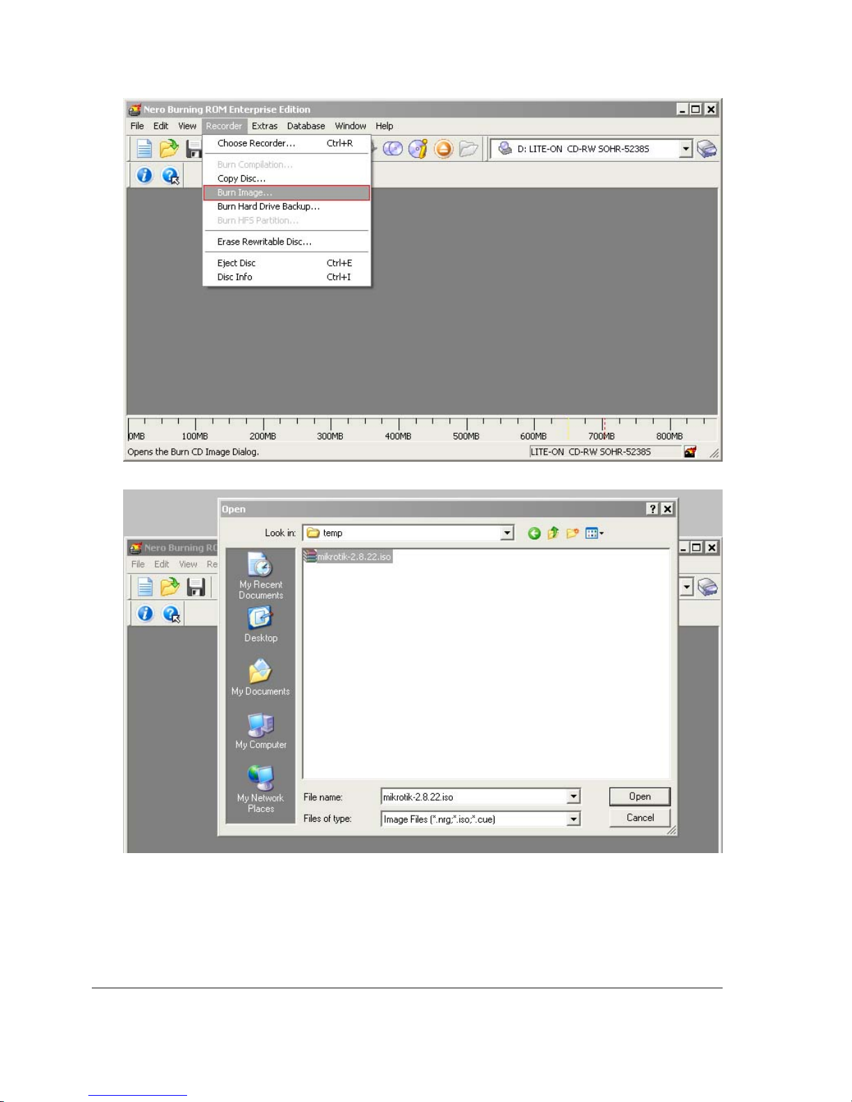
4. Select the recently extracted ISO file and click Open:
5. Finally, click Burn button:
Page 42 of 695
Copyright 1999-2007, MikroTik. All rights reserved. Mikrotik, RouterOS and RouterBOARD are trademarks of Mikrotikls SIA.
Other trademarks and registred trademarks mentioned herein are properties of their respective owners.
Page 57

6. Set the first boot device to CDROM in router's BIOS.
7. After booting from CD you will see a menu where to choose packages to install:
Welcome to MikroTik Router Software installation
Move around menu using 'p' and 'n' or arrow keys, select with 'spacebar'.
Select all with 'a', minimum with 'm'. Press 'i' to install locally or 'r' to
install remote router or 'q' to cancel and reboot.
[X] system [ ] isdn [ ] synchronous
[X] ppp [ ] lcd [ ] telephony
[X] dhcp [ ] ntp [ ] ups
[X] advanced-tools [ ] radiolan [ ] web-proxy
[ ] arlan [ ] routerboard [ ] wireless
[ ] gps [X] routing
[ ] hotspot [X] security
Follow the instructions, select needed packages, and press 'i' to install the software.
8. You will be asked for 2 questions:
Warning: all data on the disk will be erased!
Continue? [y/n]
Press [Y] to continue or [N] to abort the installation.
Do you want to keep old configuration? [y/n]:
You should choose whether you want to keep old configuration (press [Y]) or to erase the
configuration permanently (press [N]) and continue without saving it. For a fresh installation,
press [N].
Creating partition...
Formatting disk...
The system will install selected packages. After that you will be prompted to press 'Enter'.
Page 43 of 695
Copyright 1999-2007, MikroTik. All rights reserved. Mikrotik, RouterOS and RouterBOARD are trademarks of Mikrotikls SIA.
Other trademarks and registred trademarks mentioned herein are properties of their respective owners.
Page 58

Before doing that, remove the CD from your CD-Drive:
Software installed.
Press ENTER to reboot
Note: after the installation you will have to enter the Software key. See this manual how to do it.
Page 44 of 695
Copyright 1999-2007, MikroTik. All rights reserved. Mikrotik, RouterOS and RouterBOARD are trademarks of Mikrotikls SIA.
Other trademarks and registred trademarks mentioned herein are properties of their respective owners.
Page 59

Installing RouterOS with Floppies
Document revision 1.2 (Tue Jul 13 13:06:16 GMT 2004)
This document applies to MikroTik RouterOS V2.9
Table of Contents
Table of Contents
Floppy Install
Description
para
Floppy Install
Description
Another way to install the RouterOS is using floppies. You will need 9 floppies to install the
software (this includes only the system package).
1. Download the archive here . Extract it and run FloppyMaker.exe.
Read the licence agreement and press 'Yes' to continue.
Page 45 of 695
Copyright 1999-2007, MikroTik. All rights reserved. Mikrotik, RouterOS and RouterBOARD are trademarks of Mikrotikls SIA.
Other trademarks and registred trademarks mentioned herein are properties of their respective owners.
Page 60

2. After pressing 'Yes', you are introduced to useful information about RouterOS:
Press 'Continue' button to continue or 'Exit' to leave the installation.
3. You are prompted to insert disk #1 into the floppy drive:
Page 46 of 695
Copyright 1999-2007, MikroTik. All rights reserved. Mikrotik, RouterOS and RouterBOARD are trademarks of Mikrotikls SIA.
Other trademarks and registred trademarks mentioned herein are properties of their respective owners.
Page 61

Insert a blank floppy into the drive and start the copying process. Pressing 'Skip Floppy' will
skip the process to next floppy (useful in case you already have some floppies copied).
Proceed with next floppies until the following dialog occurs:
Page 47 of 695
Copyright 1999-2007, MikroTik. All rights reserved. Mikrotik, RouterOS and RouterBOARD are trademarks of Mikrotikls SIA.
Other trademarks and registred trademarks mentioned herein are properties of their respective owners.
Page 62

4. Set the dedicated computer to boot from floppy device, insert the disk #1 and boot the
computer. When it will process the first floppy, it will ask for the second, until all floppies are
processed.
Note: after the installation you will have to enter the Software key. See this manual how to do it.
Page 48 of 695
Copyright 1999-2007, MikroTik. All rights reserved. Mikrotik, RouterOS and RouterBOARD are trademarks of Mikrotikls SIA.
Other trademarks and registred trademarks mentioned herein are properties of their respective owners.
Page 63

Installing RouterOS with NetInstall
Document revision 1.3 (Mon Jul 19 12:58:25 GMT 2004)
This document applies to MikroTik RouterOS V2.9
Table of Contents
Table of Contents
NetInstall
Description
NetInstall
Description
NetInstall is a program that allows you to install MikroTiK RouterOS on a dedicated PC or
RouterBoard via Ethernet network. All you need is a blank floppy or an Ethernet device that
supports PXE (like RouterBoard 100, RouterBoard 200 and RouterBoard 500 series), an Ethernet
network between workstation and dedicated computer, and a serial null-modem console cable (for
RouterBoard routers).
NetInstall Program Parameters
Page 49 of 695
Copyright 1999-2007, MikroTik. All rights reserved. Mikrotik, RouterOS and RouterBOARD are trademarks of Mikrotikls SIA.
Other trademarks and registred trademarks mentioned herein are properties of their respective owners.
Page 64

The program runs on Windows 95/98/ME/NT/2000/XP platforms.
Netinstall parameters:
• Routers/Drives - in this list you can see all the devices waiting for installation.
• Software ID - a unique ID that is generated for licensing purposes.
• Key - a key that is generated for the Software ID. When you purchase a license, you get a key
file. Click the Browse... button next to the key field to select your key file.
• Get Key... - obtain software key from MikroTIK server:
• Software ID - ID for which the key will be generated (depending on the license level).
• Username - client's username in the Account data base.
• Password - client's password.
• Level - license level of RouterOS.
• Debit key - a key that you have paid for, but haven't generated yet.
• Debit money - money that you have on your account. To add money to your account,
use the 'add debit' link in the account server.
• Credit key - a key that you can take now, but pay later.
• Credit money - paying with credit money allows you to get your keys now and pay for
them later.
• Keep old configuration - used for reinstalling the software. If checked, the old configuration
on the router will not be overwritten, otherwise it will be lost.
Page 50 of 695
Copyright 1999-2007, MikroTik. All rights reserved. Mikrotik, RouterOS and RouterBOARD are trademarks of Mikrotikls SIA.
Other trademarks and registred trademarks mentioned herein are properties of their respective owners.
Page 65

• IP address/mask - address with subnet mask that will be assigned to ether1 interface after the
packages are installed.
• Gateway - specifies the default gateway (static route).
• Baud rate - this baud rate will be set for serial console (bps).
• Configure script - a RouterOS script to execute after the package installation. Note that not all
the devices (especially, wireless cards) may be discovered at the time this script is run, so it is
suggested to put a delay (about 20 seconds) at the start of the script to be sure that all devices
are up and running.
• Make floppy - make a bootable NetInstall floppy.
• Net booting - opens the Network Booting Settings window. Enter an IP address from your
local network. This address will be temporarily assigned to the computer where RouterOS will
be installed on.
• Install - installs the RouterOS on a computer.
• Cancel - cancel the installation.
• Sets - an entry in this list represents the choice of packages selected to install from a directory.
If you want to make your own set, browse for a folder that contains packages (*.npk files),
select needed packages in the list, and press the Save set button.
• From - type the directory where your packages are stored or press the Browse... button to
select the directory.
• Select all - selects all packages in the list
• Select none - unselects all packages in the list
Note: some of the Get key... parameters could not be available for all account types.
NetInstall Example
This example shows step-by-step instructions how to install the software on a RouterBoard 200.
1. Connect the routerboard to a switch (or a hub) as it is shown in the diagram using ether1
interface (on RouterBoard 230 it is next to the RS-232 interface):
Page 51 of 695
Copyright 1999-2007, MikroTik. All rights reserved. Mikrotik, RouterOS and RouterBOARD are trademarks of Mikrotikls SIA.
Other trademarks and registred trademarks mentioned herein are properties of their respective owners.
Page 66

2. Run NetInstall program on your workstation (you can download it here . It is necessary to
extract the packages (*.npk files) on your hard drive.
NetInstall v1.10
Page 52 of 695
Copyright 1999-2007, MikroTik. All rights reserved. Mikrotik, RouterOS and RouterBOARD are trademarks of Mikrotikls SIA.
Other trademarks and registred trademarks mentioned herein are properties of their respective owners.
Page 67

3. Enter the Boot Server Client's IP address. Use an address from a network to which belongs
your NIC (in this case 172.16.0.0/24). This IP address will be temporarily assigned to the
routerboard.
4. Set the RouterBoard to boot from Ethernet interface. To do this, enter the RouterBoard BIOS
(press any key when prompted):
RouterBIOS v1.3.0 MikroTik (tm) 2003-2004
RouterBOARD 230 (CPU revision B1)
CPU frequency: 266 MHz
Memory size: 64 MB
Press any key within 1 second to enter setup.
You will see a list of available commands. To set up the boot device, press the 'o' key:
RouterBIOS v1.3.0
What do you want to configure?
d - boot delay
k - boot key
s - serial console
l - debug level
o - boot device
b - beep on boot
v - vga to serial
t - ata translation
p - memory settings
m - memory test
u - cpu mode
f - pci back-off
r - reset configuration
g - bios upgrade through serial port
c - bios license information
x - exit setup
your choice: o - boot device
Press the 'e' key to make the RouterBoard to boot from Ethernet interface:
Select boot device:
* i - IDE
e - Etherboot
1 - Etherboot (timeout 15s), IDE
2 - Etherboot (timeout 1m), IDE
3 - Etherboot (timeout 5m), IDE
4 - Etherboot (timeout 30m), IDE
5 - IDE, try Etherboot first on next boot (15s)
6 - IDE, try Etherboot first on next boot (1m)
7 - IDE, try Etherboot first on next boot (5m)
8 - IDE, try Etherboot first on next boot (30m)
your choice: e - Etherboot
When this is done, the RouterBoard BIOS will return to the first menu. Press the 'x' key to exit
Page 53 of 695
Copyright 1999-2007, MikroTik. All rights reserved. Mikrotik, RouterOS and RouterBOARD are trademarks of Mikrotikls SIA.
Other trademarks and registred trademarks mentioned herein are properties of their respective owners.
Page 68

from BIOS. The router will reboot.
5. When booting up, the RouterBoard will try to boot from its Ethernet device. If successful, the
Workstation will give to this RouterBoard an IP address, specified in Network Booting
Settings. After this process, the RouterBoard will be waiting for installation.
On the workstation, there will appear a new entry in Routers/Drives list:
You can identify the router by MAC address in the list. Click on the desired entry and you will
be able to configure installation parameters .
When done, press the Install button to install RouterOS.
6. When the installation process has finished, press 'Enter' on the console or 'Reboot' button in the
NetInstall program. Remember to set the boot device back to IDE in the RouterBoard BIOS.
Page 54 of 695
Copyright 1999-2007, MikroTik. All rights reserved. Mikrotik, RouterOS and RouterBOARD are trademarks of Mikrotikls SIA.
Other trademarks and registred trademarks mentioned herein are properties of their respective owners.
Page 69

Configuration Management
Document revision 1.6 (Mon Sep 19 12:55:52 GMT 2005)
This document applies to MikroTik RouterOS V2.9
Table of Contents
Table of Contents
Summary
Description
System Backup
Description
Command Description
Example
Example
The Export Command
Description
Command Description
Example
The Import Command
Description
Command Description
Example
Configuration Reset
Description
Command Description
Notes
Example
General Information
Summary
This manual introduces you with commands which are used to perform the following functions:
• system backup
• system restore from a backup
• configuration export
• configuration import
• system configuration reset
Description
The configuration backup can be used for backing up MikroTik RouterOS configuration to a binary
file, which can be stored on the router or downloaded from it using FTP. The configuration restore
can be used for restoring the router's configuration from a backup file.
Page 55 of 695
Copyright 1999-2007, MikroTik. All rights reserved. Mikrotik, RouterOS and RouterBOARD are trademarks of Mikrotikls SIA.
Other trademarks and registred trademarks mentioned herein are properties of their respective owners.
Page 70

The configuration export can be used for dumping out MikroTik RouterOS configuration to the
console screen or to a text (script) file, which can be downloaded from the router using FTP. The
configuration import can be used to import the router configuration script from a text file.
System reset command is used to erase all configuration on the router. Before doing that, it might
be useful to backup the router's configuration.
Note! In order to be sure that the backup will not fail, system backup load command must be used
on the same computer with the same hardware where system backup save was done.
System Backup
Home menu level: /system backup
Description
The save command is used to store the entire router configuration in a backup file. The file is
shown in the /file submenu. It can be downloaded via ftp to keep it as a backup for your
configuration.
To restore the system configuration, for example, after a /system reset, it is possible to upload that
file via ftp and load that backup file using load command in /system backup submenu.
Command Description
load name=[filename] - Load configuration backup from a file
save name=[filename] - Save configuration backup to a file
Example
To save the router configuration to file test:
[admin@MikroTik] system backup> save name=test
Configuration backup saved
[admin@MikroTik] system backup>
To see the files stored on the router:
[admin@MikroTik] > file print
# NAME TYPE SIZE CREATION-TIME
0 test.backup backup 12567 sep/08/2004 21:07:50
[admin@MikroTik] >
Example
To load the saved backup file test:
[admin@MikroTik] system backup> load name=test
Restore and reboot? [y/N]: y
...
The Export Command
Command name: /export
Page 56 of 695
Copyright 1999-2007, MikroTik. All rights reserved. Mikrotik, RouterOS and RouterBOARD are trademarks of Mikrotikls SIA.
Other trademarks and registred trademarks mentioned herein are properties of their respective owners.
Page 71

Description
The export command prints a script that can be used to restore configuration. The command can be
invoked at any menu level, and it acts for that menu level and all menu levels below it. If the
argument from is used, then it is possible to export only specified items. In this case export does
not descend recursively through the command hierarchy. export also has the argument file, which
allows you to save the script in a file on the router to retrieve it later via FTP.
Command Description
file=[filename] - saves the export to a file
from=[number] - specifies from which item to start to generate the export file
Example
[admin@MikroTik] > ip address print
Flags: X - disabled, I - invalid, D - dynamic
# ADDRESS NETWORK BROADCAST INTERFACE
0 10.1.0.172/24 10.1.0.0 10.1.0.255 bridge1
1 10.5.1.1/24 10.5.1.0 10.5.1.255 ether1
[admin@MikroTik] >
To make an export file:
[admin@MikroTik] ip address> export file=address
[admin@MikroTik] ip address>
To make an export file from only one item:
[admin@MikroTik] ip address> export file=address1 from=1
[admin@MikroTik] ip address>
To see the files stored on the router:
[admin@MikroTik] > file print
# NAME TYPE SIZE CREATION-TIME
0 address.rsc script 315 dec/23/2003 13:21:48
1 address1.rsc script 201 dec/23/2003 13:22:57
[admin@MikroTik] >
To export the setting on the display use the same command without the file argument:
[admin@MikroTik] ip address> export from=0,1
# nov/13/2004 13:25:30 by RouterOS 2.9
# software id = MGJ4-MAN
#
/ ip address
add address=10.1.0.172/24 network=10.1.0.0 broadcast=10.1.0.255 \
interface=bridge1 comment="" disabled=no
add address=10.5.1.1/24 network=10.5.1.0 broadcast=10.5.1.255 \
interface=ether1 comment="" disabled=no
[admin@MikroTik] ip address>
The Import Command
Command name: /import
Description
Page 57 of 695
Copyright 1999-2007, MikroTik. All rights reserved. Mikrotik, RouterOS and RouterBOARD are trademarks of Mikrotikls SIA.
Other trademarks and registred trademarks mentioned herein are properties of their respective owners.
Page 72

The root level command /import [file_name] restores the exported information from the specified
file. This is used to restore configuration or part of it after a /system reset event or anything that
causes configuration data loss.
Note that it is impossible to import the whole router configuration using this feature. It can only be
used to import a part of configuration (for example, firewall rules) in order to spare you some
typing.
Command Description
file=[filename] - loads the exported configuration from a file to router
Example
To load the saved export file use the following command:
[admin@MikroTik] > import address.rsc
Opening script file address.rsc
Script file loaded successfully
[admin@MikroTik] >
Configuration Reset
Command name: /system reset
Description
The command clears all configuration of the router and sets it to the default including the login
name and password ('admin' and no password), IP addresses and other configuration is erased,
interfaces will become disabled. After the reset command router will reboot.
Command Description
reset - erases router's configuration
Notes
If the router has been installed using netinstall and had a script specified as the initial configuration,
the reset command executes this script after purging the configuration. To stop it doing so, you will
have to reinstall the router.
Example
[admin@MikroTik] > system reset
Dangerous! Reset anyway? [y/N]: n
action cancelled
[admin@MikroTik] >
Page 58 of 695
Copyright 1999-2007, MikroTik. All rights reserved. Mikrotik, RouterOS and RouterBOARD are trademarks of Mikrotikls SIA.
Other trademarks and registred trademarks mentioned herein are properties of their respective owners.
Page 73

FTP (File Transfer Protocol) Server
Document revision 2.3 (Fri Jul 08 15:52:48 GMT 2005)
This document applies to MikroTik RouterOS V2.9
Table of Contents
Table of Contents
Summary
Specifications
Related Documents
File Transfer Protocol Server
Description
Property Description
Command Description
General Information
Summary
MikroTik RouterOS implements File Transfer Protocol (FTP) server feature. It is intended to be
used for software packages uploading, configuration script exporting and importing procedures, as
well as for storing HotSpot servlet pages.
Specifications
Packages required: system
License required: level1
Home menu level: /file
Standards and Technologies: FTP (RFC 959)
Hardware usage: Not significant
Related Documents
• Software Package Management
• Configuration Management
File Transfer Protocol Server
Home menu level: /file
Description
MikroTik RouterOS has an industry standard FTP server feature. It uses ports 20 and 21 for
communication with other hosts on the network.
Uploaded files as well as exported configuration or backup files can be accessed under /file menu.
There you can delete unnecessary files from your router.
Page 59 of 695
Copyright 1999-2007, MikroTik. All rights reserved. Mikrotik, RouterOS and RouterBOARD are trademarks of Mikrotikls SIA.
Other trademarks and registred trademarks mentioned herein are properties of their respective owners.
Page 74

Authorization for FTP service uses router's system user account names and passwords.
Property Description
creation-time ( read-only: time ) - item creation date and time
name ( read-only: name ) - item name
size ( read-only: integer ) - package size in bytes
type ( read-only: file | directory | unknown | script | package | backup ) - item type
Command Description
print - shows a list of files stored - shows contents of files less that 4kb long - offers to edit file's
contents with editor - sets the file's contents to 'content'
Page 60 of 695
Copyright 1999-2007, MikroTik. All rights reserved. Mikrotik, RouterOS and RouterBOARD are trademarks of Mikrotikls SIA.
Other trademarks and registred trademarks mentioned herein are properties of their respective owners.
Page 75

MAC Level Access (Telnet and Winbox)
Document revision 2.3 (June 22, 2007, 15:33 GMT)
This document applies to MikroTik RouterOS V2.9
Table of Contents
Table of Contents
Summary
Specifications
Related Documents
MAC Telnet Server
Property Description
Notes
Example
MAC WinBox Server
Property Description
Notes
Example
Monitoring Active Session List
Property Description
Example
MAC Telnet Client
Example
General Information
Summary
MAC telnet is used to provide access to a router that has no IP address set. It works just like IP
telnet. MAC telnet is possible between two MikroTik RouterOS routers only.
Specifications
Packages required: system
License required: level1
Home menu level: /tool , /tool mac-server
Standards and Technologies: MAC Telnet
Hardware usage: Not significant
Related Documents
• Software Package Management
• WinBox
• Ping
• MNDP
Page 61 of 695
Copyright 1999-2007, MikroTik. All rights reserved. Mikrotik, RouterOS and RouterBOARD are trademarks of Mikrotikls SIA.
Other trademarks and registred trademarks mentioned herein are properties of their respective owners.
Page 76

MAC Telnet Server
Home menu level: /tool mac-server
Property Description
interface ( name | all ; default: all ) - interface name to which the mac-server clients will connect
• all - all interfaces
Notes
There is an interface list in this submenu level. If you add some interfaces to this list, you allow
MAC telnet to that interface. Disabled (disabled=yes) item means that interface is not allowed to
accept MAC telnet sessions on that interface.
Example
To enable MAC telnet server on ether1 interface only:
[admin@MikroTik] tool mac-server> print
Flags: X - disabled
# INTERFACE
0 all
[admin@MikroTik] tool mac-server> remove 0
[admin@MikroTik] tool mac-server> add interface=ether1 disabled=no
[admin@MikroTik] tool mac-server> print
Flags: X - disabled
# INTERFACE
0 ether1
[admin@MikroTik] tool mac-server>
MAC WinBox Server
Home menu level: /tool mac-server mac-winbox
Property Description
interface ( name | all ; default: all ) - interface name to which it is alowed to connect with Winbox
using MAC-based protocol
• all - all interfaces
Notes
There is an interface list in this submenu level. If you add some interfaces to this list, you allow
MAC Winbox to that interface. Disabled (disabled=yes) item means that interface is not allowed to
accept MAC Winbox sessions on that interface.
Example
To enable MAC Winbox server on ether1 interface only:
[admin@MikroTik] tool mac-server mac-winbox> print
Page 62 of 695
Copyright 1999-2007, MikroTik. All rights reserved. Mikrotik, RouterOS and RouterBOARD are trademarks of Mikrotikls SIA.
Other trademarks and registred trademarks mentioned herein are properties of their respective owners.
Page 77

Flags: X - disabled
# INTERFACE
0 all
[admin@MikroTik] tool mac-server mac-winbox> remove 0
[admin@MikroTik] tool mac-server mac-winbox> add interface=ether1 disabled=no
[admin@MikroTik] tool mac-server mac-winbox> print
Flags: X - disabled
# INTERFACE
0 ether1
[admin@MikroTik] tool mac-server mac-winbox>
Monitoring Active Session List
Home menu level: /tool mac-server sessions
Property Description
interface ( read-only: name ) - interface to which the client is connected to
src-address ( read-only: MAC address ) - client's MAC address
uptime ( read-only: time ) - how long the client is connected to the server
Example
To see active MAC Telnet sessions:
[admin@MikroTik] tool mac-server sessions> print
# INTERFACE SRC-ADDRESS UPTIME
0 wlan1 00:0B:6B:31:08:22 00:03:01
[admin@MikroTik] tool mac-server sessions>
MAC Telnet Client
Command name: /tool mac-telnet [MAC-address]
Example
[admin@MikroTik] > /tool mac-telnet 00:02:6F:06:59:42
Login: admin
Password:
Trying 00:02:6F:06:59:42...
Connected to 00:02:6F:06:59:42
MMM MMM KKK TTTTTTTTTTT KKK
MMMM MMMM KKK TTTTTTTTTTT KKK
MMM MMMM MMM III KKK KKK RRRRRR OOOOOO TTT III KKK KKK
MMM MM MMM III KKKKK RRR RRR OOO OOO TTT III KKKKK
MMM MMM III KKK KKK RRRRRR OOO OOO TTT III KKK KKK
MMM MMM III KKK KKK RRR RRR OOOOOO TTT III KKK KKK
MikroTik RouterOS 2.9 (c) 1999-2004 http://www.mikrotik.com/
Terminal linux detected, using multiline input mode
[admin@MikroTik] >
Page 63 of 695
Copyright 1999-2007, MikroTik. All rights reserved. Mikrotik, RouterOS and RouterBOARD are trademarks of Mikrotikls SIA.
Other trademarks and registred trademarks mentioned herein are properties of their respective owners.
Page 78

Serial Console and Terminal
Document revision 2.1 (Wed Mar 03 16:12:49 GMT 2004)
This document applies to MikroTik RouterOS V2.9
Table of Contents
Table of Contents
Summary
Specifications
Related Documents
Description
Serial Console Configuration
Description
Configuring Console
Property Description
Example
Using Serial Terminal
Description
Property Description
Notes
Example
Console Screen
Description
Property Description
Notes
Example
General Information
Summary
The Serial Console and Terminal are tools, used to communicate with devices and other systems
that are interconnected via serial port. The serial terminal may be used to monitor and configure
many devices - including modems, network devices (including MikroTik routers), and any device
that can be connected to a serial (asynchronous) port.
Specifications
Packages required: system
License required: level1
Home menu level: /system , /system console , /system serial-terminal
Standards and Technologies: RS-232
Hardware usage: Not significant
Related Documents
• Software Package Management
Page 64 of 695
Copyright 1999-2007, MikroTik. All rights reserved. Mikrotik, RouterOS and RouterBOARD are trademarks of Mikrotikls SIA.
Other trademarks and registred trademarks mentioned herein are properties of their respective owners.
Page 79

Description
The Serial Console (managed side) feature allows configuring one serial port of the MikroTik
router for access to the router's Terminal Console over the serial port. A special null-modem cable
is required to connect the router's serial port with the workstation's or laptop's serial (COM) port. A
terminal emulation program, e.g., HyperTerminal, should be run on the workstation. You can also
use MikroTik RouterOS to connect to an another Serial Console (for example, on a Cisco router).
Several customers have described situations where the Serial Terminal (managing side) feature
would be useful:
• in a mountaintop where a MikroTik wireless installation sits next to equipment (including
switches and Cisco routers) that can not be managed in-band (by telnet through an IP network)
• monitoring weather-reporting equipment through a serial-console
• connection to a high-speed microwave modem that needed to be monitored and managed by a
serial-console connection
With the serial-terminal feature of the MikroTik, up to 132 (and, maybe, even more) devices can be
monitored and controlled
Serial Console Configuration
Description
A special null-modem cable should be used for connecting to the serial console. The Serial Console
cabling diagram for DB9 connectors is as follows:
Router Side (DB9f) Signal Direction Side (DB9f)
1, 6 CD, DSR IN 4
2 RxD IN 3
3 TxD OUT 2
4 DTR OUT 1, 6
5 GND - 5
7 RTS OUT 8
8 CTS IN 7
Configuring Console
Home menu level: /system console
Property Description
enabled ( yes | no ; default: no ) - whether serial console is enabled or not
free ( read-only: text ) - console is ready for use
Page 65 of 695
Copyright 1999-2007, MikroTik. All rights reserved. Mikrotik, RouterOS and RouterBOARD are trademarks of Mikrotikls SIA.
Other trademarks and registred trademarks mentioned herein are properties of their respective owners.
Page 80

port ( name ; default: serial0 ) - which port should the serial terminal listen to
term ( text ) - name for the terminal
used ( read-only: text ) - console is in use
vcno ( read-only: integer ) - number of virtual console - [Alt]+[F1] represents '1', [Alt]+[F2] - '2',
etc.
wedged ( read-only: text ) - console is currently not available
Example
To enable Serial Console with terminal name MyConsole:
[admin@MikroTik] system console> set 0 disabled=no term=MyConsole
[admin@MikroTik] system console> print
Flags: X - disabled, W - wedged, U - used, F - free
# PORT VCNO TERM
0 F serial0 MyConsole
1 W 1 linux
2 W 2 linux
3 W 3 linux
4 W 4 linux
5 W 5 linux
6 W 6 linux
7 W 7 linux
8 W 8 linux
[admin@MikroTik] system console>
To check if the port is available or used (parameter used-by):
[admin@MikroTik] system serial-console> /port print detail
0 name=serial0 used-by=Serial Console baud-rate=9600 data-bits=8 parity=none
stop-bits=1 flow-control=none
1 name=serial1 used-by="" baud-rate=9600 data-bits=8 parity=none stop-bits=1
flow-control=none
[admin@MikroTik] system serial-console>
Using Serial Terminal
Command name: /system serial-terminal
Description
The command is used to communicate with devices and other systems that are connected to router
via serial port.
All keyboard input is forwarded to the serial port and all data from the port is output to the
connected device. After exiting with [Ctrl]+[Q], the control signals of the port are lowered. The
speed and other parameters of serial port may be configured in the /port directory of router console.
No terminal translation on printed data is performed. It is possible to get the terminal in an unusable
state by outputting sequences of inappropriate control characters or random data. Do not connect to
devices at an incorrect speed and avoid dumping binary data.
Property Description
port ( name ) - port name to use
Page 66 of 695
Copyright 1999-2007, MikroTik. All rights reserved. Mikrotik, RouterOS and RouterBOARD are trademarks of Mikrotikls SIA.
Other trademarks and registred trademarks mentioned herein are properties of their respective owners.
Page 81

Notes
[Ctrl]+[Q] and [Ctrl]+[X] have special meaning and are used to provide a possibility of exiting from
nested serial-terminal sessions:
To send [Ctrl]+[X] to to serial port, press [Ctrl]+[X] [Ctrl]+[X]
To send [Ctrl]+[Q] to to serial port, press [Ctrl]+[X] [Ctrl]+[Q]
Example
To connect to a device connected to the serial1 port:
[admin@MikroTik] system> serial-terminal serial1
[Type Ctrl-Q to return to console]
[Ctrl-X is the prefix key]
Console Screen
Home menu level: /system console screen
Description
This facility is created to change line number per screen if you have a monitor connected to router.
Property Description
line-count ( 25 | 40 | 50 ) - number of lines on monitor
Notes
This parameter is applied only to a monitor, connected to the router.
Example
To set monitor's resolution from 80x25 to 80x40:
[admin@MikroTik] system console screen> set line-count=40
[admin@MikroTik] system console screen> print
line-count: 40
[admin@MikroTik] system console screen>
Page 67 of 695
Copyright 1999-2007, MikroTik. All rights reserved. Mikrotik, RouterOS and RouterBOARD are trademarks of Mikrotikls SIA.
Other trademarks and registred trademarks mentioned herein are properties of their respective owners.
Page 82

Software Package Management
Document revision 1.3 (Mon Jul 11 12:42:44 GMT 2005)
This document applies to MikroTik RouterOS V2.9
Table of Contents
Table of Contents
Summary
Related Documents
Description
Installation (Upgrade)
Description
Notes
Uninstallation
Description
Notes
Example
Downgrading
Description
Command Description
Example
Disabling and Enabling
Description
Notes
Example
Unscheduling
Description
Notes
Example
System Upgrade
Description
Property Description
Example
Adding Package Source
Description
Property Description
Notes
Example
Software Package List
Description
General Information
Summary
The MikroTik RouterOS is distributed in the form of software packages. The basic functionality of
the router and the operating system itself is provided by the system software package. Other
Page 68 of 695
Copyright 1999-2007, MikroTik. All rights reserved. Mikrotik, RouterOS and RouterBOARD are trademarks of Mikrotikls SIA.
Other trademarks and registred trademarks mentioned herein are properties of their respective owners.
Page 83

packages contain additional software features as well as support to various network interface cards.
Specifications
License required: level1
Home menu level: /system package
Standards and Technologies: FTP
Hardware usage: Not significant
Related Documents
• Basic Setup Guide
• Driver Management
• Software Version Management
• License Management
• Installing RouterOS with NetInstall
• Installing RouterOS with CD-Install
• Installing RouterOS with Floppies
Description
Features
The modular software package system of MikroTik RouterOS has the following features:
• Ability to extend RouterOS functions by installing additional software packages
• Optimal usage of the storage space by employing modular/compressed system
• Unused software packages can be uninstalled
• The RouterOS functions and the system itself can be easily upgraded
• Multiple packages can be installed at once
• The package dependency is checked before installing a software package. The package will not
be installed, if the required software package is missing
• The version of the feature package should be the same as that of the system package
• The packages can be uploaded on the router using ftp and installed only when the router is
going for shutdown during the reboot process
• If the software package file can be uploaded to the router, then the disk space is sufficient for
the installation of the package
• The system can be downgraded to an older version by uploading the needed packages to router
via FTP binary mode. After that, execute command /system package downgrade
Installation (Upgrade)
Page 69 of 695
Copyright 1999-2007, MikroTik. All rights reserved. Mikrotik, RouterOS and RouterBOARD are trademarks of Mikrotikls SIA.
Other trademarks and registred trademarks mentioned herein are properties of their respective owners.
Page 84

Description
Installation or upgrade of the MikroTik RouterOS software packages can be done by uploading the
newer version of the software package to the router and rebooting it.
The software package files are compressed binary files, which can be downloaded from the
MikroTik's web page download section. The full name of the software package consists of a
descriptive name, version number and extension .npk, exempli gratia system-2.9.11.npk,
routerboard-2.9.11.npk. Package routeros-x86 contains all necessary packages for RouterOS
installation and upgrading for RouterBOARD 200 and PC. Package routeros-rb500 contains all
necessary packages for RouterOS installation and upgrading for RouterBOARD 500. These
packages are preferred installation and upgrading method.
You should check the available hard disk space prior to downloading the package file by issuing
/system resource print command. If there is not enough free disk space for storing the upgrade
packages, it can be freed up by uninstalling some software packages, which provide functionality
not required for your needs. If you have a sufficient amount of free space for storing the upgrade
packages, connect to the router using ftp. Use user name and password of a user with full access
privileges.
Step-by-Step
• Connect to the router using ftp client
• Select the BINARY mode file transfer
• Upload the software package files to the router
• Check the information about the uploaded software packages using the /file print command
• Reboot the router by issuing the /system reboot command or by pressing Ctrl+Alt+Del keys
at the router's console
• After reboot, verify that the packages were installed correctly by issuing /system package
print command
Notes
The packages uploaded to the router should retain the original name and also be in lowercase.
The installation/upgrade process is shown on the console screen (monitor) attached to the router.
The Free Demo License do not allow software upgrades using ftp. You should do a complete
reinstall from floppies, or purchase the license.
Before upgrading the router, please check the current version of the system package and the
additional software packages. The versions of additional packages should match the version number
of the system software package. The version of the MikroTik RouterOS system software (and the
build number) are shown before the console login prompt. Information about the version numbers
and build time of the installed MikroTik RouterOS software packages can be obtained using the
/system package print command.
Do not use routeros-x86 and routeros-rb500 packges to upgrade from version 2.8 or older. To
upgrade use regular packages.
Page 70 of 695
Copyright 1999-2007, MikroTik. All rights reserved. Mikrotik, RouterOS and RouterBOARD are trademarks of Mikrotikls SIA.
Other trademarks and registred trademarks mentioned herein are properties of their respective owners.
Page 85

Packages wireless-test, rstp-bridge-test, routing-test are included in routeros-x86 and
routeros-rb500 packages, but disabled by default.
Uninstallation
Command name: /system package uninstall
Description
Usually, you do not need to uninstall software packages. However, if you have installed a wrong
package, or you need additional free space to install a new one, you have to uninstall some unused
packages.
Notes
If a package is marked for uninstallation, but it is required for another (dependent) package, then the
marked package cannot be uninstalled. You should uninstall the dependent package too. For the list
of package dependencies see the 'Software Package List; section below. The system package will
not be uninstalled even if marked for uninstallation.
Example
Suppose we need to uninstall security package from the router:
[admin@MikroTik] system package> print
# NAME VERSION SCHEDULED
0 system 2.9.11
1 routing 2.9.11
2 dhcp 2.9.11
3 hotspot 2.9.11
4 wireless 2.9.11
5 web-proxy 2.9.11
6 advanced-tools 2.9.11
7 security 2.9.11
8 ppp 2.9.11
9 routerboard 2.9.11
[admin@MikroTik] system package> uninstall security
[admin@MikroTik] > .. reboot
Downgrading
Command name: /system package downgrade
Description
Downgrade option allows you to downgrade the software via FTP without losing your license key
or reinstalling the router.
Step-by-Step
• Connect to the router using ftp client
• Select the BINARY mode file transfer
Page 71 of 695
Copyright 1999-2007, MikroTik. All rights reserved. Mikrotik, RouterOS and RouterBOARD are trademarks of Mikrotikls SIA.
Other trademarks and registred trademarks mentioned herein are properties of their respective owners.
Page 86

• Upload the software package files to the router
• Check the information about the uploaded software packages using the /file print command
• Execute command /system package downgrade. The router will downgrade and reboot.
• After reboot, verify that the packages were installed correctly by issuing /system package
print command
Command Description
downgrade - this command asks your confirmation and reboots the router. After reboot the
software is downgraded (if all needed packages were uploaded to the router)
Example
To downgrade the RouterOS (assuming that all needed packages are already uploaded):
[admin@MikroTik] system package> downgrade
Router will be rebooted. Continue? [y/N]: y
system will reboot shortly
Disabling and Enabling
Command name: /system package disable , /system package enable
Description
You can disable packages making them invisible for the system and later enable them, bringing the
system back to the previous state. It is useful if you don't want to uninstall a package, but just turn
off its functionality.
Notes
If a package is marked for disabling, but it is required for another (dependent) package, then the
marked package cannot be disabled. You should disable or uninstall the dependent package too. For
the list of package dependencies see the 'Software Package List; section below.
If any of the test packages will be enabled (for example wireless-test and routing-test packages, that
are included in routeros-x86.npk and routeros-rb500.npk) system automaticly will disable regular
packages that conflict with them.
Example
Suppose we need to test wireless-test package features:
[admin@MikroTik] system package> print
[admin@MikroTik] > system package pr
Flags: X - disabled
# NAME VERSION SCHEDULED
0 system 2.9.11
1 routerboard 2.9.11
2 X wireless-test 2.9.11
3 ntp 2.9.11
4 routeros-rb500 2.9.11
Page 72 of 695
Copyright 1999-2007, MikroTik. All rights reserved. Mikrotik, RouterOS and RouterBOARD are trademarks of Mikrotikls SIA.
Other trademarks and registred trademarks mentioned herein are properties of their respective owners.
Page 87

5 X rstp-bridge-test 2.9.11
6 wireless 2.9.11
7 webproxy-test 2.9.11
8 routing 2.9.11
9 X routing-test 2.9.11
10 ppp 2.9.11
11 dhcp 2.9.11
12 hotspot 2.9.11
13 security 2.9.11
14 advanced-tools 2.9.11
[admin@MikroTik] system package> enable wireless-test
[admin@MikroTik] system package> .. reboot
Unscheduling
Command name: /system package unschedule
Description
Unschedule option allows to cancel pending uninstall, disable or enable actions for listed packages.
Notes
packages marked for uninstallation, disabling or enabling on reboot in column "schedule" will have
a note, warning about changes.
Example
Suppose we need to cancel wireless-test package uninstallation action scheduled on reboot:
[admin@MikroTik] system package> print
[admin@MikroTik] > system package pr
Flags: X - disabled
# NAME VERSION SCHEDULED
0 system 2.9.11
1 routerboard 2.9.11
2 wireless-test 2.9.11 scheduled for uninstall
3 ntp 2.9.11
4 routeros-rb500 2.9.11
5 X rstp-bridge-test 2.9.11
6 wireless 2.9.11
7 webproxy-test 2.9.11
8 routing 2.9.11
9 X routing-test 2.9.11
10 ppp 2.9.11
11 dhcp 2.9.11
12 hotspot 2.9.11
13 security 2.9.11
14 advanced-tools 2.9.11
[admin@MikroTik] system package> unschedule wireless-test
[admin@MikroTik] system package>
System Upgrade
Home menu level: /system upgrade
Description
This submenu gives you the ability to download RouterOS software packages from a remote
RouterOS router.
Page 73 of 695
Copyright 1999-2007, MikroTik. All rights reserved. Mikrotik, RouterOS and RouterBOARD are trademarks of Mikrotikls SIA.
Other trademarks and registred trademarks mentioned herein are properties of their respective owners.
Page 88

Step-by-Step
• Upload desired RouterOS packages to a router (not the one that you will upgrade)
• Add this router's IP address, user name and password to /system upgrade
upgrade-package-source
• Refresh available software package list /system upgrade refresh
• See available packages, using /system upgrade print command
• Download selected or all packages from the remote router, using the download or
download-all command
Property Description
download - download packages from list by specifying their numbers
download-all - download all packages that are needed for the upgrade (packages which are
available in '/system package print' list)
name ( read-only: name ) - package name
refresh - updates currently available package list
source ( read-only: IP address ) - source IP address of the router from which the package list entry
is retrieved
status ( read-only: available | scheduled | downloading | downloaded | installed ) - package status
version ( read-only: text ) - version of the package
Example
See the available packages:
[admin@MikroTik] system upgrade> print
# SOURCE NAME VERSION STATUS COMPLETED
0 192.168.25.8 advanced-tools 2.9.11 available
1 192.168.25.8 dhcp 2.9.11 available
2 192.168.25.8 hotspot 2.9.11 available
3 192.168.25.8 isdn 2.9.11 available
4 192.168.25.8 ntp 2.9.11 available
5 192.168.25.8 ppp 2.9.11 available
6 192.168.25.8 routerboard 2.9.11 available
7 192.168.25.8 routing 2.9.11 available
8 192.168.25.8 security 2.9.11 available
9 192.168.25.8 synchronous 2.9.11 available
10 192.168.25.8 system 2.9.11 available
11 192.168.25.8 telephony 2.9.11 available
12 192.168.25.8 ups 2.9.11 available
13 192.168.25.8 web-proxy 2.9.11 available
14 192.168.25.8 wireless 2.9.11 available
[admin@MikroTik] system upgrade>
To upgrade chosen packages:
[admin@MikroTik] system upgrade> download 0,1,2,5,6,7,8,9,10,13,14
[admin@MikroTik] system upgrade> print
# SOURCE NAME VERSION STATUS COMPLETED
0 192.168.25.8 advanced-tools 2.9.11 downloaded
1 192.168.25.8 dhcp 2.9.11 downloading 16 %
2 192.168.25.8 hotspot 2.9.11 scheduled
3 192.168.25.8 isdn 2.9.11 available
Page 74 of 695
Copyright 1999-2007, MikroTik. All rights reserved. Mikrotik, RouterOS and RouterBOARD are trademarks of Mikrotikls SIA.
Other trademarks and registred trademarks mentioned herein are properties of their respective owners.
Page 89

4 192.168.25.8 ntp 2.9.11 available
5 192.168.25.8 ppp 2.9.11 scheduled
6 192.168.25.8 routerboard 2.9.11 scheduled
7 192.168.25.8 routing 2.9.11 scheduled
8 192.168.25.8 security 2.9.11 scheduled
9 192.168.25.8 synchronous 2.9.11 scheduled
10 192.168.25.8 system 2.9.11 scheduled
11 192.168.25.8 telephony 2.9.11 available
12 192.168.25.8 ups 2.9.11 available
13 192.168.25.8 web-proxy 2.9.11 scheduled
14 192.168.25.8 wireless 2.9.11 scheduled
[admin@MikroTik] system upgrade>
Adding Package Source
Home menu level: /system upgrade upgrade-package-source
Description
In this submenu you can add remote routers from which to download the RouterOS software
packages.
Property Description
address ( IP address ) - source IP address of the router from which the package list entry will be
retrieved
password ( text ) - password of the remote router
user ( text ) - username of the remote router
Notes
After specifying a remote router in /system upgrade upgrade-package-source, you can type
/system upgrade refresh to refresh the package list and /system upgrade print to see all available
packages.
Example
To add a router with IP address 192.168.25.8, username admin and no password:
/system upgrade upgrade-package-source add address=192.168.25.8 user=admin
[admin@MikroTik] system upgrade upgrade-package-source> print
# ADDRESS USER
0 192.168.25.8 admin
[admin@MikroTik] system upgrade upgrade-package-source>
Software Package List
Description
System Software Package
The system software package provides the basic functionality of the MikroTik RouterOS, namely:
Page 75 of 695
Copyright 1999-2007, MikroTik. All rights reserved. Mikrotik, RouterOS and RouterBOARD are trademarks of Mikrotikls SIA.
Other trademarks and registred trademarks mentioned herein are properties of their respective owners.
Page 90

• IP address management, ARP, static IP routing, policy routing, firewall (packet filtering,
content filtering, masquerading, and static NAT), traffic shaping (queues), IP traffic
accounting, MikroTik Neighbour Discovery, IP Packet Packing, DNS client settings, IP
service (servers)
• Ethernet interface support
• IP over IP tunnel interface support
• Ethernet over IP tunnel interface support
• driver management for Ethernet ISA cards
• serial port management
• local user management
• export and import of router configuration scripts
• backup and restore of the router's configuration
• undo and redo of configuration changes
• network diagnostics tools (ping, traceroute, bandwidth tester, traffic monitor)
• bridge support
• system resource management
• package management
• telnet client and server
• local and remote logging facility
• winbox server as well as winbox executable with some plugins
After installing the MikroTik RouterOS, a free license should be obtained from MikroTik to enable
the basic system functionality.
Additional Software Feature Packages
The table below shows additional software feature packages, extended functionality provided by
them, the required prerequisites and additional licenses, if any.
Name Contents Prerequisites Additional License
advanced-tools
email client, pingers,
netwatch and other
utilities
none none
arlan
support for DSSS
2.4GHz 2mbps
Aironet ISA cards
none
2.4GHz/5GHz
Wireless Client
dhcp
DHCP server and
client support
none none
gps
support for GPS
devices
none none
hotspot HotSpot gateway none any additional license
Page 76 of 695
Copyright 1999-2007, MikroTik. All rights reserved. Mikrotik, RouterOS and RouterBOARD are trademarks of Mikrotikls SIA.
Other trademarks and registred trademarks mentioned herein are properties of their respective owners.
Page 91

isdn
support for ISDN
devices
ppp none
lcd
support for
informational LCD
display
none none
ntp
network time
protocol support
none none
ppp
support for PPP,
PPTP, L2TP, PPPoE
and ISDN PPP
none none
radiolan
Provides support for
5.8GHz RadioLAN
cards
none
2.4GHz/5GHz
Wireless Client
routerboard
support for
RouterBoard-specific
functions and utilities
none none
routing
support for RIP,
OSPF and BGP4
none none
security
support for IPSEC,
SSH and secure
WinBox connections
none none
synchronous
support for Frame
Relay and Moxa
C101, Moxa C502,
Farsync, Cyclades
PC300, LMC SBE
and XPeed
synchronous cards
none Synchronous
telephony
IP telephony support
(H.323)
none none
thinrouter-pcipc
forces
PCI-to-CardBus
Bridge to use IRQ 11
as in ThinRouters
none none
ups
APC Smart Mode
UPS support
none none
web-proxy
HTTP Web proxy
support
none none
wireless
Provides support for
Cisco Aironet cards,
PrismII and Atheros
wireless stations and
APs
none
2.4GHz/5GHz
Wireless Client /
2.4GHz/5GHz
Wireless Server
(optional)
Page 77 of 695
Copyright 1999-2007, MikroTik. All rights reserved. Mikrotik, RouterOS and RouterBOARD are trademarks of Mikrotikls SIA.
Other trademarks and registred trademarks mentioned herein are properties of their respective owners.
Page 92

Software Version Management
Document revision 1.4 (Tue Oct 18 12:24:57 GMT 2005)
This document applies to MikroTik RouterOS V2.9
Table of Contents
Table of Contents
Summary
Specifications
System Upgrade
Related Documents
Description
Property Description
Example
Adding Package Source
Description
Property Description
Notes
Example
General Information
Summary
To upgrade RouterOS to a more recent version, you can simply transfer the packages to router via
ftp, using the binary transfer mode, and then just rebooting the router.
This manual discusses a more advanced method how to upgrade a router automatically. If you have
more than one router then this can be useful.
Specifications
Packages required: system
License required: level1
Home menu level: /system upgrade
Standards and Technologies: None
Hardware usage: Not significant
System Upgrade
Home menu level: /system upgrade
Related Documents
• Software Package Management
• License Management
Page 78 of 695
Copyright 1999-2007, MikroTik. All rights reserved. Mikrotik, RouterOS and RouterBOARD are trademarks of Mikrotikls SIA.
Other trademarks and registred trademarks mentioned herein are properties of their respective owners.
Page 93

Description
In this submenu you can see available packages and are able to choose which to install from a
remote router.
At first you upload new packages to the router via ftp, using the binary data transfer mode. Then
(from another router, which you will upgrade) add the router's IP on which are the packages listed
in the /system upgrade upgrade-package-source list. Afterwards, you type /system upgrade
refresh to update the available package list. To see all available packages, choose /system upgrade
print command.
Property Description
download - download packages from list by specifying their numbers
download-all - download all packages that are needed for the upgrade (packages which are
available in '/system package print' list)
name ( read-only: name ) - package name
refresh - updates currently available package list
source ( read-only: IP address ) - source IP address of the router from which the package list entry
is retrieved
status ( read-only: available | scheduled | downloading | downloaded | installed ) - package status
version ( read-only: text ) - version of the package
Example
See the available packages:
[admin@MikroTik] system upgrade> print
# SOURCE NAME VERSION STATUS COMPLETED
0 192.168.25.8 advanced-tools 2.9 available
1 192.168.25.8 dhcp 2.9 available
2 192.168.25.8 hotspot 2.9 available
3 192.168.25.8 isdn 2.9 available
4 192.168.25.8 ntp 2.9 available
5 192.168.25.8 ppp 2.9 available
6 192.168.25.8 routerboard 2.9 available
7 192.168.25.8 routing 2.9 available
8 192.168.25.8 security 2.9 available
9 192.168.25.8 synchronous 2.9 available
10 192.168.25.8 system 2.9 available
11 192.168.25.8 telephony 2.9 available
12 192.168.25.8 ups 2.9 available
13 192.168.25.8 web-proxy 2.9 available
14 192.168.25.8 wireless 2.9 available
[admin@MikroTik] system upgrade>
To upgrade chosen packages:
[admin@MikroTik] system upgrade> download 0,1,2,5,6,7,8,9,10,13,14
[admin@MikroTik] system upgrade> print
# SOURCE NAME VERSION STATUS COMPLETED
0 192.168.25.8 advanced-tools 2.9 downloaded
1 192.168.25.8 dhcp 2.9 downloading 16 %
2 192.168.25.8 hotspot 2.9 scheduled
3 192.168.25.8 isdn 2.9 available
4 192.168.25.8 ntp 2.9 available
5 192.168.25.8 ppp 2.9 scheduled
Page 79 of 695
Copyright 1999-2007, MikroTik. All rights reserved. Mikrotik, RouterOS and RouterBOARD are trademarks of Mikrotikls SIA.
Other trademarks and registred trademarks mentioned herein are properties of their respective owners.
Page 94

6 192.168.25.8 routerboard 2.9 scheduled
7 192.168.25.8 routing 2.9 scheduled
8 192.168.25.8 security 2.9 scheduled
9 192.168.25.8 synchronous 2.9 scheduled
10 192.168.25.8 system 2.9 scheduled
11 192.168.25.8 telephony 2.9 available
12 192.168.25.8 ups 2.9 available
13 192.168.25.8 web-proxy 2.9 scheduled
14 192.168.25.8 wireless 2.9 scheduled
[admin@MikroTik] system upgrade>
Adding Package Source
Home menu level: /system upgrade upgrade-package-source
Description
Here can you specify IP address, username and password of the remote hosts from which you will
be able to get packages.
Property Description
address ( IP address ) - source IP address of the router from which the package list entry will be
retrieved
user ( text ) - username of the remote router
Notes
After specifying a remote router in '/system upgrade upgrade-package-source', you can type
'/system upgrade refresh' to refresh the package list and '/system upgrade print' to see all available
packages.
Adding an upgrade source you will be prompted for a password.
Example
To add a router, with username admin and no password, from which the packages will be retrieved:
[admin@MikroTik] system upgrade upgrade-package-source> print
# ADDRESS USER
0 192.168.25.8 admin
[admin@MikroTik] system upgrade upgrade-package-source>
Page 80 of 695
Copyright 1999-2007, MikroTik. All rights reserved. Mikrotik, RouterOS and RouterBOARD are trademarks of Mikrotikls SIA.
Other trademarks and registred trademarks mentioned herein are properties of their respective owners.
Page 95

SSH (Secure Shell) Server and Client
Document revision 2.0 (Fri Mar 05 09:09:40 GMT 2004)
This document applies to MikroTik RouterOS V2.9
Table of Contents
Table of Contents
Summary
Specifications
Related Documents
Additional Documents
SSH Server
Description
Property Description
Example
SSH Client
Property Description
Example
General Information
Summary
SSH Client authenticates server and encrypts traffic between the client and server. You can use
SSH just the same way as telnet - you run the client, tell it where you want to connect to, give your
username and password, and everything is the same after that. After that you won't be able to tell
that you're using SSH. The SSH feature can be used with various SSH Telnet clients to securely
connect to and administrate the router.
The MikroTik RouterOS supports:
• SSH 1.3, 1.5, and 2.0 protocol standards
• server functions for secure administration of the router
• telnet session termination with 40 bit RSA SSH encryption is supported
• secure ftp is supported
• preshared key authentication is not supported
The MikroTik RouterOS has been tested with the following SSH telnet terminals:
• PuTTY
• Secure CRT
• OpenSSH GNU/Linux client
Specifications
Packages required: security
Page 81 of 695
Copyright 1999-2007, MikroTik. All rights reserved. Mikrotik, RouterOS and RouterBOARD are trademarks of Mikrotikls SIA.
Other trademarks and registred trademarks mentioned herein are properties of their respective owners.
Page 96

License required: level1
Home menu level: /system ssh
Standards and Technologies: SSH
Hardware usage: Not significant
Related Documents
• Package Management
Additional Documents
• http://www.freessh.org/
SSH Server
Home menu level: /ip service
Description
SSH Server is already up and running after MikroTik router installation. The default port of the
service is 22. You can set a different port number.
Property Description
name ( name ) - service name
port ( integer : 1 ..65535 ) - port the service listens to
address ( IP address | netmask ; default: 0.0.0.0/0 ) - IP address from which the service is
accessible
Example
Let's change the default SSH port (22) to 65 on which the SSH server listens for requests:
[admin@MikroTik] ip service> set ssh port=65
[admin@MikroTik] ip service> print
Flags: X - disabled, I - invalid
# NAME PORT ADDRESS CERTIFICATE
0 telnet 23 0.0.0.0/0
1 ftp 21 0.0.0.0/0
2 www 80 0.0.0.0/0
3 ssh 65 0.0.0.0/0
4 X www-ssl 443 0.0.0.0/0
[admin@MikroTik] ip service>
SSH Client
Command name: /system ssh
Property Description
port ( integer ; default: 22 ) - which TCP port to use for SSH connection to a remote host
Page 82 of 695
Copyright 1999-2007, MikroTik. All rights reserved. Mikrotik, RouterOS and RouterBOARD are trademarks of Mikrotikls SIA.
Other trademarks and registred trademarks mentioned herein are properties of their respective owners.
Page 97

user ( text ; default: admin ) - username for the SSH login
Example
[admin@MikroTik] > /system ssh 192.168.0.1 user=pakalns port=22
admin@192.168.0.1's password:
MMM MMM KKK TTTTTTTTTTT KKK
MMMM MMMM KKK TTTTTTTTTTT KKK
MMM MMMM MMM III KKK KKK RRRRRR OOOOOO TTT III KKK KKK
MMM MM MMM III KKKKK RRR RRR OOO OOO TTT III KKKKK
MMM MMM III KKK KKK RRRRRR OOO OOO TTT III KKK KKK
MMM MMM III KKK KKK RRR RRR OOOOOO TTT III KKK KKK
MikroTik RouterOS 2.9rc7 (c) 1999-2005 http://www.mikrotik.com/
Terminal unknown detected, using single line input mode
[admin@MikroTik] >
Page 83 of 695
Copyright 1999-2007, MikroTik. All rights reserved. Mikrotik, RouterOS and RouterBOARD are trademarks of Mikrotikls SIA.
Other trademarks and registred trademarks mentioned herein are properties of their respective owners.
Page 98

Telnet Server and Client
Document revision 2.1 (Mon Jul 19 07:31:04 GMT 2004)
This document applies to MikroTik RouterOS V2.9
Table of Contents
Table of Contents
Summary
Specifications
Related Documents
Telnet Server
Description
Example
Telnet Client
Description
Example
General Information
Summary
MikroTik RouterOS has a build-in Telnet server and client features. These two are used to
communicate with other systems over a network.
Specifications
Packages required: system
License required: level1
Home menu level: /system , /ip service
Standards and Technologies: Telnet (RFC 854)
Hardware usage: Not significant
Related Documents
• Package Management
• System Resource Management
Telnet Server
Home menu level: /ip service
Description
Telnet protocol is intended to provide a fairly general, bi-directional, eight-bit byte oriented
communications facility. The main goal is to allow a standard method of interfacing terminal
devices to each other.
Page 84 of 695
Copyright 1999-2007, MikroTik. All rights reserved. Mikrotik, RouterOS and RouterBOARD are trademarks of Mikrotikls SIA.
Other trademarks and registred trademarks mentioned herein are properties of their respective owners.
Page 99

MikroTik RouterOS implements industry standard Telnet server. It uses port 23, which must not be
disabled on the router in order to use the feature.
You can enable/disable this service or allow the use of the service to certain IP addresses.
Example
[admin@MikroTik] ip service> print detail
Flags: X - disabled, I - invalid
0 name="telnet" port=23 address=0.0.0.0/0
1 name="ftp" port=21 address=0.0.0.0/0
2 name="www" port=80 address=0.0.0.0/0
3 name="hotspot" port=8088 address=0.0.0.0/0
4 name="ssh" port=65 address=0.0.0.0/0
5 X name="hotspot-ssl" port=443 address=0.0.0.0/0 certificate=none
[admin@MikroTik] ip service>
Telnet Client
Command name: /system telnet [IP address] [port]
Description
MikroTik RouterOS telnet client is used to connect to other hosts in the network via Telnet
protocol.
Example
An example of Telnet connection:
[admin@MikroTik] > system telnet 172.16.0.1
Trying 172.16.0.1...
Connected to 172.16.0.1.
Escape character is '^]'.
MikroTik v2.9
Login: admin
Password:
MMM MMM KKK TTTTTTTTTTT KKK
MMMM MMMM KKK TTTTTTTTTTT KKK
MMM MMMM MMM III KKK KKK RRRRRR OOOOOO TTT III KKK KKK
MMM MM MMM III KKKKK RRR RRR OOO OOO TTT III KKKKK
MMM MMM III KKK KKK RRRRRR OOO OOO TTT III KKK KKK
MMM MMM III KKK KKK RRR RRR OOOOOO TTT III KKK KKK
MikroTik RouterOS 2.9 (c) 1999-2004 http://www.mikrotik.com/
Terminal unknown detected, using single line input mode
[admin@MikroTik] >
Page 85 of 695
Copyright 1999-2007, MikroTik. All rights reserved. Mikrotik, RouterOS and RouterBOARD are trademarks of Mikrotikls SIA.
Other trademarks and registred trademarks mentioned herein are properties of their respective owners.
Page 100

Terminal Console
Document revision 1.0 (Mon Nov 8 13:15:54 GMT 2004)
This document applies to MikroTik RouterOS V2.9
Table of Contents
Table of Contents
Summary
Specifications
Related Documents
Common Console Functions
Description
Example
Lists and Item Names
Description
Notes
Example
Quick Typing
Description
Notes
Additional Information
Description
General Commands
Description
Command Description
Safe Mode
Description
General Information
Summary
The Terminal Console is used for accessing the MikroTik Router's configuration and management
features using text terminals, id est remote terminal clients or locally attached monitor and
keyboard. The Terminal Console is also used for writing scripts. This manual describes the general
console operation principles. Please consult the Scripting Manual on some advanced console
commands and on how to write scripts.
Specifications
Packages required: system
License required: level1
Hardware usage: Not significant
Related Documents
• Scripting Host and Complementary Tools
Page 86 of 695
Copyright 1999-2007, MikroTik. All rights reserved. Mikrotik, RouterOS and RouterBOARD are trademarks of Mikrotikls SIA.
Other trademarks and registred trademarks mentioned herein are properties of their respective owners.
 Loading...