

Operator’s
Manual
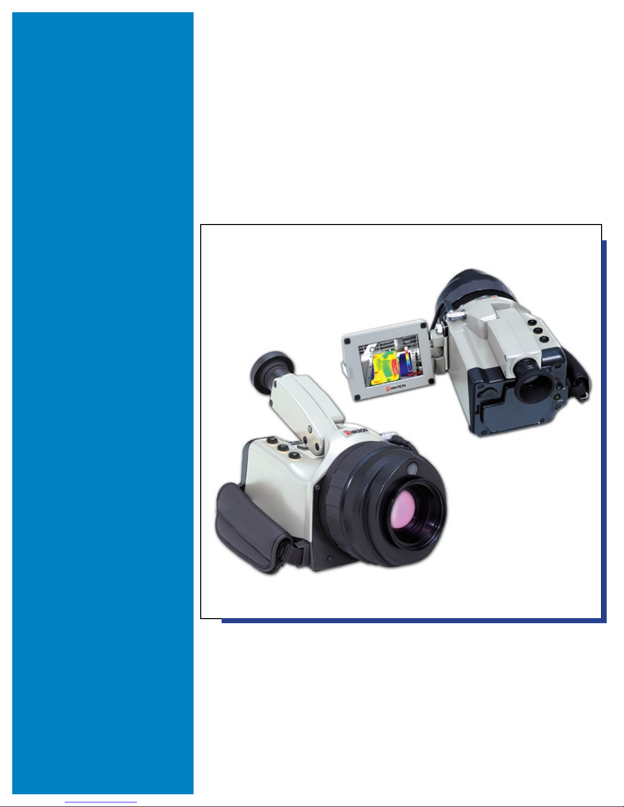
MikroScan 7600PRO
Thermal Imager
MIKRON INFRARED, INC.
16 THORNTON ROAD
OAKLAND, NJ 07436, USA
Tel: 1-201-405-0900
Fax: 1-201-405-0090
URL: http:\\www.mikroninfrared.com


Table of Contents
Section 1
Section 2
General Information 1
1.1 How To Use This Manual 1
1.2 Conventions 1
1.3 Operator Training 1
1.4 Precautions 2
1.4.1 Power 2
1.4.2 Battery Pack
1.4.3 Cable, adapter, cord 3
1.4.4 Neck Strap 3
1.4.5 Environmental Conditions for Use and Storage 3
1.5 Warranty
1.6 Regulatory Information 4
1.7 Unpacking and Inspection 5
1.8 Procedure for Factory Repair and Return 6
4
2
Introduction 7
2.1 System Overview 7
2.2 Construction 8
2.2 Construction 9
2.3 Key Panel Functions 10
2.4 Camera Interfaces 11
2.5 On Board Image Processing Software 12
On Board Image Processing Software —Standard Type Menu 13
On Board Image Processing Software —Classic Type Menu 14
2.6 Camera Functions 15
Button Control Features 15
Main Menu Functions 15
2.7 Standard Camera Accessories 28
Section 3
Getting Started 29
3.1 Charging the Batteries 29
3.2 Connecting the Power Supply 30
3.2.1 Before You Begin 30
3.2.2 Attaching the Battery Pack 31
3.2.3 Connecting the AC Adapter 31
3.3 Handling the Lens Protection Cap 32
3.3.1 Removing the Lens Cap 32
3.3.2 Attaching the Lens Cap 32
3.4 Handling the Memory Card 33
3.4.1 Inserting the Memory Card 33
MikroScan 7600PRO
i
i
Operator’s Manual
Catalog 11180-94
V15.4F 050406

3.4.2 Removing the Memory Card 33
3.5 Viewing Your First Image 34
3.6 Accessing the MikroScan 7600PRO Expanded
Menu Functions 35
3.6.1 Using the Standard Type Navigational Structure 35
3.6.2 Using the Classic Type Navigational Structure 36
3.7 Working with the LCD Display 38
3.8 Selecting a Lens Option 39
3.9 Customizing your MikroScan 7600PRO 40
3.9.1 Establishing the Initial Setup Values 40
3.9.1.1 Selecting the Temperature Unit 40
3.9.1.2 Customizing the Memory Card File Name 42
3.9.1.3 Setting the Auto Mode Function 45
3.9.1.4 Setting the Language 47
3.9.1.5 Activating the IEEE 1394 Functionality 48
3.9.1.6 Setting the Date Format 48
3.9.1.7 Setting the Date 50
3.9.1.8 Setting the Time 51
3.9.1.9 Displaying the Date and Time 53
3.9.1.10 Selecting a Navigational Structure 54
3.9.2 Establishing the Save Setup Values 56
3.9.2.1 Selecting a Voice Memo Recording Option 56
3.9.2.2 Selecting the Image Save Format 58
3.9.2.3 Selecting the Visible Save Option 59
3.9.3 Establishing the Analyze Setup Values 61
3.9.3.1 Setting the Multipoint Display Mode 61
3.9.3.2 Activating/Deactivating the Box Temperature Option 64
3.9.4 Establishing the Display Setup Values 66
3.9.4.1 Setting the NUC (Non Uniformity Correction) Mode 66
3.9.4.2 Setting the L&S (Level & Sensitivity OR Level & Span)
Mode 69
3.9.4.3 Setting the Threshold for Spatial Filtering 71
3.9.4.4 Clearing/Showing Display Elements 73
3.9.4.5 Clearing/Showing the Status Bar 77
3.9.4.6 Clearing/Showing the Color Bar 79
3.9.4.7 Clearing/Showing the Battery Status Indicator 80
3.9.4.8 Setting the TV System (Video Output Mode) 82
3.9.4.9 Setting the TV Scanning Mode 82
3.9.4.10 Adjusting the LCD Brightness Level 82
3.9.5 Establishing the Auto Standby Parameters 84
3.9.5.1 Activating the Auto Standby Feature 84
3.9.5.2 Deactivating the Auto Standby Feature 86
3.10 WorkingwithCongurationFiles 88
3.10.1 Savingacongurationle 88
3.10.2 Loadingasavedcongurationle 90
MikroScan 7600PRO
ii
ii
Operator’s Manual
Catalog 11180-94
V15.4F 050406

3.11 Information on the MikroScan 7600PRO Firmware Version 91
3.12 Finishing 91
Section 4
Basic Operation 93
4.1 Toggling between the Run and Freeze Modes 93
4.1.1 Switching to Freeze Mode 93
4.1.2 Returning to Run Mode 93
4.2 Using the Power Standby Mode 94
4.2.1 Working with the Power Standby ON Function 94
4.2.2 Working with the Power Standby Auto Function 95
4.3 Selecting the Temperature Range and Mode 95
4.3.1 Selecting the Temperature Range (Option 1) 95
4.3.2 Selecting the Temperature Range Mode Setting 97
4.4 Switching Between Ranges
4.4.1 Using the Manual Range Formatting Option with L/S Link 98
4.5 Working with the Color Palette Options 100
4.5.1 Choosing a Color Palette 100
4.5.2 Switching between the Color and Monochrome Display 102
4.5.2.1 Using the Standard Type Menu 102
4.5.2.2 Using the Classic Type Menu 103
4.6 Adjusting the Focus 104
4.6.1 Using the Focus Indicator Bar with the Standard Type Menu 104
4.6.2 Using the Focus Indicator Bar with the Classic Type Menu 105
4.6.3 Manual Focusing 107
4.7 Adjusting the Temperature Level 107
4.8 Adjusting the Temperature Span 108
4.9 Adjusting the Sensitivity 109
4.10 Using the Auto Processing Functions 110
4.10.1 Performing the Full Auto Function 110
4.10.2 Performing the Auto Focus Function 111
4.10.3 Performing the Auto Level & Sens/Level & Span Function 111
4.11 Working with the Averaging Function (S/N Improvement) 112
4.12 Working with the Image Zoom Function 113
4.13 Using the Memo Function 115
4.13.1 Creating a Memo using the Character Input Method 115
4.13.2 Adding Multiple Memos Using the Character Input Method 118
4.13.3 Applying a Memo Designation using the File Selection
Method 120
4.13.4 Changing a Memo 121
4.13.5 Deleting an Memo Designation 124
4.13.5.1 Deleting a Single Character 124
4.13.5.2 Deleting all Characters at Once 127
98
iii
iii
MikroScan 7600PRO
Operator’s Manual
Catalog 11180-94
V15.4F 050406

Section 5
Images and Image Files 129
5.1 Working with the Save Function 129
5.1.1 Saving Image Data as .SIT Files 129
5.1.2 Saving Image Data as .BMP Files 131
5.1.3 Adding a Voice Memo to a New Image 132
5.2 Reviewing Saved Images using the MikroScan 7600PRO 135
5.2.1 Reviewing .SIT Images Using the Replay File Feature 135
5.2.2 Reviewing .BMP Images Using the Replay File Feature 137
5.2.3 Reviewing Images Using the Thumbnail Feature. 139
5.3 Working with Images Stored to Real-Time Memory 141
5.3.2 Saving RTM Images to the Compact Flash Memory Card 142
5.3.2.1 Saving Individual Image Frames as .SIT Files 143
5.3.2.2 Saving Individual Image Frames as .BMP Files 144
5.3.2.3 Using the RTM Save All Feature 145
5.4 Using the Memory Card Management Options 148
5.4.1 Making Directories 148
5.4.2 Selecting Directories 149
5.4.3 Deleting Files 151
5.4.4 Renumbering Files 153
5.4.5 Formatting the Memory Card 154
5.4.6 Working with Memory Card Error Messages 155
Section 6
Data Analysis 157
6.1 Adjusting for Ambient Compensation 157
6.1.1 Accessing the Ambient Compensation Mode Settings 157
6.1.2 Setting Ambient Compensation Using the Parameter Mode 158
6.1.2.1 Setting the Atmospheric Temperature Value 159
6.1.2.2 Setting the Relative Humidity Value 161
6.1.2.3 Setting the Object Distance 162
6.1.3 Setting Ambient Compensation Using the Value Mode 164
6.1.3.1 Setting the Atmospheric Temperature Value 165
6.1.3.2 Setting the Compensation Value 166
6.1.4 Deactivating the Ambient Compensation Mode 168
6.2 Adjusting for Background Compensation 169
6.3 Working with the Gain Control Function 171
6.3.1 Selecting a Gain Control Option 171
6.3.2 Disabling the Gain Control Option
6.4 Working with the Multi-Point Temperature Display Options 174
6.4.1 Setting a Single Point 175
6.4.2 Setting Multiple Points 177
6.4.3 Changing Set Point Positions 179
6.4.4 Deleting Individual Set Point Positions 181
6.4.5 Deleting All Set Point Positions 184
173
iv
iv
MikroScan 7600PRO
Operator’s Manual
Catalog 11180-94
V15.4F 050406

6.5 Working with Emissivity Settings 185
6.5.1 Setting the Display Emissivity Using a Numerical Value
(Run Mode) 185
6.5.1.1 Using the Standard Type Menu 185
6.5.1.2 Using the Classic Type Menu 186
6.5.2 Setting the Display Emissivity and Ambient Temperature Using a
Numerical Value (Freeze Mode) 187
6.5.2.1 Using the Standard Type Menu 187
6.5.2.2 Using the Classic Type Menu 190
6.5.3 Setting the Display Emissivity Using the On-Board Emissivity
Tables 193
6.5.4 Working with Point Emissivities 195
6.5.4.1 Setting the Display to Show Emissivity Effects on
Various Points 195
6.5.4.2 Setting Emissivity Values for One or More Points 197
6.5.4.3 Deleting Individual Emissivity Values 198
6.5.4.4 Deleting All Set Emissivity Values 201
6.6 Working with Boxes 202
6.6.1 Adding a Box 202
6.6.2 Adding Multiple Boxes 206
6.6.3 Deleting a Box 209
6.6.4 Deleting all Boxes 211
6.7 Working with the Max/Min Temperature Display 212
6.7.1 Selecting the Max/Min Temperature Option—Whole Display 213
6.7.2 SettingtheMax/MinTemperatureOption—DenedBox 215
6.7.3 Canceling the Max/Min Temperature Option 217
6.8 Working with the Composite Image Function 219
6.8.1 Creating a Composite Image 219
6.8.2 Fitting the Composite Image 221
6.9 Working with the Multi Sense Display Settings 222
6.10 Working with the ISO Thermal Function 223
6.10.1 Customizing the Range of a Single ISO Thermal Band 223
6.10.2 Adding Multiple ISO Thermal Bands 225
6.10.3 Modifying Existing ISO Thermal Bands 227
6.10.4 Erasing an Individual ISO Thermal Band 229
6.10.5 Erasing all ISO Thermal Bands 231
6.11 Working with the Wave Function 233
6.12 Working with the Event Functions 235
6.12.1 Setting the Event Condition 235
6.12.2 Selecting a Range Area 238
6.12.3 Choosing to Display an Alarm Warning Message 239
6.12.4 Choosing to Sound an Audible Warning 241
6.12.5 Choosing to Freeze Measurements 243
6.12.6 Saving Measurements to a Compact Flash Card 244
MikroScan 7600PRO
v
v
Operator’s Manual
Catalog 11180-94
V15.4F 050406

6.12.6.1 Selecting the PC Card Option 244
6.12.6.2 Selecting the PC Card Interval Option 246
6.12.6.3 Selecting the PC Card Time Delay Option 248
6.12.6.4 Selecting the PC Card Save Visible Image Option 249
6.12.7 Saving Measurements to Real-time Memory (RTM) 251
6.12.7.1 Selecting the RTM Option 251
6.12.7.2 Setting the RTM Freeze Option 253
6.12.7.3 Selecting the RTM Interval Option 256
6.12.7.4 Selecting the RTM Frame Delay Option 258
Section 7
Section 8
Advanced Operations 261
7.1 Working with External LCD Displays 261
7.1.1 Connecting the LCD Display 261
7.1.2 Disconnecting the LCD Display 261
7.1.3 Setting the RS-232C Baud Rate (if necessary) 262
7.1.4 Setting the RS-232C Data Format (if necessary) 263
7.2 Working with External Video Displays 265
7.2.1 Connecting the Video Display Cable 265
7.2.2 Setting the Video Display Parameters 265
7.2.2.1 Setting the TV System (Video Output Mode) 265
7.2.2.2 Setting the TV Scanning Mode 267
7.3 Working with Communication Interfaces 269
7.3.1 Connecting the communication cable 269
7.3.2 Activating the IEEE 1394 Functionality 270
7.4 Calibrating the Instrument 271
7.4.1 Performing a REF CAL (Reference Calibration) 272
7.4.2 Performing a ERSP CAL (External Response Calibration) 272
7.5 Returning all Settings to Default Values 273
Principle of Thermal Imaging 275
8.1 Infrared Radiation 275
8.2 Emissivity 276
8.3 Blackbody Radiation 277
8.4 Blackbody Type Source and Emissivity 279
8.5 Determining Emissivity 280
8.6 Background Noise 281
8.7 Practical Measurement 282
8.8 Emissivity of Various Materials 283
vi
MikroScan 7600PRO
Operator’s Manual
Catalog 11180-94
V15.4F 050406

Section 9
Appendix 287
9.1 After Use Care 287
9.2 Maintenance 287
9.3 Troubleshooting Symptoms 288
9.4 Troubleshooting Error Messages 290
9.5 MikroScan7600PROSpecications 291
Index 293
vii
MikroScan 7600PRO
Operator’s Manual
Catalog 11180-94
V15.4F 050406

To ensure consistent document formatting, this page was intentionally left blank
viii
MikroScan 7600PRO
Operator’s Manual
Catalog 11180-94
V15.4F 050406
Section
1
General Information
Congratulations on your selection of Mikron’s MikroScan 7600PRO for your thermal
imaging applications. You have chosen a ne, precision instrument that will provide
years of reliable service if you adhere to the precautions, recommendations, and
procedures for operation, maintenance, and care as outlined in this manual.
Therefore, it is recommended that you read this manual in its entirety prior to operating
your MikroScan 7600PRO camera.
1.1 How To Use This Manual
This manual contains information designed to familiarize you with the features and
functions of the MikroScan 7600PRO and to provide step by step instructions on the
instrument’s operation. Information about infrared temperature measurement theory
and thermal imaging is also included together with a guide to care, maintenance and
troubleshooting.
1.2 Conventions
1) Headings of main sections appear in italicized, bold type.
In general:
Notes contain
information that is
important.
Tips contain information that is helpful.
2) Headings of sub-sections appear in bold type.
3) Menu or display options appear as [BOXED TEXT].
4) BUTTON designations are indicated in capital letters.
5) Warnings, Cautions, Notes, and Tips are designated in the side bar.
The following notations appear before instructions intended to avoid
injury to personnel or damage to equipment.
This may cause injury to personnel or damage to user’s equipment.
This may cause damage to the product.
1.3 Operator Training
To best understand and utilize the measurements and images derived from the
operation of this instrument, the operator should understand the basics of heat transfer
and infrared radiation theory. Notes on these basics can be found in Section 8 of this
manual. Education and training in these subjects should be provided by qualied personnel.
MikroScan 7600PRO
1
Operator’s Manual
Catalog 11180-94
V15.4F 050406

Section 1
General Information
1.4 Precautions
The following precautions should be followed when handling and operating your
MikroScan 7600PRO thermal imaging camera.
1.4.1 Power
Follow the connection procedures described in Section 3.2 of this manual.
1) Do not use an AC Adapter or batteries other than those provided or
specied by Mikron Infrared, Inc.
2) Do not use a source for line power that is not in accordance with
specications.
3) Do not allow line voltage to exceed the specied noise or uctuations
limits.
1.4.2 Battery Pack
Follow the connection procedures described in Section 3.2 of this manual.
1) Do not disassemble the battery pack or batteries.
If you disassemble the battery pack, the internal circuit will
break and the safety systems for charging and discharging will
not operate properly which may cause overheating, re, or
explosion. Also, if the battery pack is disassembled, it may
generate irritating gas or cause the negative electrode to over-
heat and catch re.
2) Do not short-circuit the battery pack or battery.
3) Do not expose the battery pack or battery to ame or water.
If the battery pack or battery is exposed to ame it may catch
re or explode. If it is exposed to water, the internal circuit
will break and the safety systems for charging and discharging
will not operate properly which may cause overheating, re, or
explosion. Also exposure to water may cause the shielded portion of the battery to corrode and leak.
4) Do not solder the terminal of the battery pack.
The heat may melt the case or break the internal circuit and the
safety systems for charging and discharging will not operate
properly which may cause overheating, re, or explosion. Also
if the battery is heated at 100°C or more, the plastic material of
the gasket and separator may break and cause leakage, overheating, re, or explosion.
5) Do not operate the camera in an enclosed case.
Flammable gas generated by the battery may catch re from
sparks generated from a motor or switch, etc.
6) Do not install the battery terminals (+) and (-) in reverse.
MikroScan 7600PRO
2
Operator’s Manual
Catalog 11180-94
V15.4F 050406

Section 1
General Information
7) Do not charge, overcharge, or charge in reverse with higher
current than the rating.
This may cause the battery to generate gas, catch re or explode.
8) Do not use the battery in equipment that has not been provided or
specied by Mikron Infrared, Inc., as being compatible for use with
the battery.
9) Do not use a charger other than the charger provided or specied by
Mikron Infrared, Inc., as being compatible for use with the battery.
1.4.3 Cable, adapter, cord
Follow the connection procedure for the instrument, AC Adapter and power connector as
described in Section 3.2 of this manual.
1) Do not wet or immerse the adapter in water.
2) Do not use a damaged AC Adapter or extension cord.
3) Do not disconnect the battery or AC Adapter from the instrument with
the power switched to on.
1.4.4 Neck Strap
Follow the neck strap attachment procedure as described in Section 3.3 of this manual.
1) Do not use the strap around your neck when the instrument is in transit between locations.
2) Be especially aware of protruding objects on which the strap can
become hooked.
1.4.5 Environmental Conditions for Use and Storage
1) Do not exceed the storage temperature limits of -20°C to 70°C.
2) Do not exceed the operating temperature limits of -15°C to 50°C.
3) Do not exceed the humidity limit of 30% to 90% Relative Humidity
(non-condensing).
4) Do not use or store the instrument in the presence of poison, ammable gas or materials, explosives, corrosive atmospheres or steam.
5) Do not use or store the instrument where it will be subjected to shock
and vibration extremes.
6) Do not use or store the instrument for extended periods in direct,
intense sunlight or in a location subject to extreme increases in
temperature (e.g. in a car).
7) Do not use or store the instrument in extremely dusty environments.
8) Do not use or store the instrument in the presence of strong electro-
magnetic elds, if possible.
9) Do not use or store the instrument under wet conditions such as
rain or snow unless the hatch, terminal cover and battery have been
secured.
MikroScan 7600PRO
3
Operator’s Manual
Catalog 11180-94
V15.4F 050406

Section 1
General Information
1.5 Warranty
Mikron Infrared, Inc., will repair or replace any parts or material found defective which
are due to aws in design or manufacture when reported in writing within one year from
the date of sale (unless another term is agreed to in writing by Mikron as part of the
sale). Once a return authorization is approved and assigned, instruments to be repaired
under this warranty are to be returned to Mikron, shipping charges prepaid by the user
who assumes all risk and cost of shipping to and from the plant.
In the event that Mikron, in its sole judgment and discretion, determines, for purpose of
repair, that an on-site inspection is required, this warranty does not cover transportation
of factory-trained service personnel to and from the installation site or expenses while
there.
This warranty is void if the instrument is disassembled, tampered with, altered or otherwise damaged, without prior written consent from Mikron, or if considered by Mikron
to be abused or used in abnormal conditions.
This warranty shall constitute the exclusive remedy available to the user and shall be
considered a condition of sale and use.
The manufacturer, Mikron Infrared, Inc., shall not be liable for any loss, or damage,
including loss of prot or consequential damages resulting from, or attributed to, the use
of its product or resulting from a defect in design or manufacture of the product.
The user shall determine the particular use to which the product shall be applied and the
seller excludes and disclaims any warranty that the product is t for such use.
1.6 Regulatory Information
This section contains information that shows how the Infrared camera complies with
regulations in certain regions. Any modications to the Infrared camera not expressly
approved by the manufacturer could void the authority to operate the Infrared camera in
these regions.
USA
This Infrared camera generates, uses, and can radiate radio frequency energy and may
interfere with radio and television reception. The Infrared camera complies with the
limits for a Class B digital device used exclusively as industrial or commercial test
equipment., pursuant to Part 15 Subpart B Sec. 15.103 c. of the FCC Rules.
These limits are designed to provide reasonable protection against harmful interference.
However, there is no guarantee that interference will not occur in a particular installation.
General conditions of operation.
(a) Persons operating intentional or unintentional radiators shall not
be deemed to have any vested or recognizable right to continued
use of any given frequency by virtue of prior registration or
certication of equipment, or, for power line carrier systems, on
the basis of prior notication of use pursuant to Sec. 90.63(g) of
this chapter.
MikroScan 7600PRO
4
Operator’s Manual
Catalog 11180-94
V15.4F 050406
Section 1
General Information
(b) Operation of an intentional, unintentional, or incidental radia-
tor is subject to the conditions that no harmful interference
is caused and that interference must be accepted that may
be caused by the operation of an authorized radio station, by
another intentional or unintentional radiator, by industrial,
scientic and medical (ISM) equipment, or by an incidental
radiator.
The package should be
allowed to stabilize at
room temperature before
removing the instrument
to prevent the formation
of condensation.
(c) The operator of a radio frequency device shall be required to
cease operating the device upon notication by a Commission
representative that the device is causing harmful interference.
Operation shall not resume until the condition causing the harmful interference has been corrected.
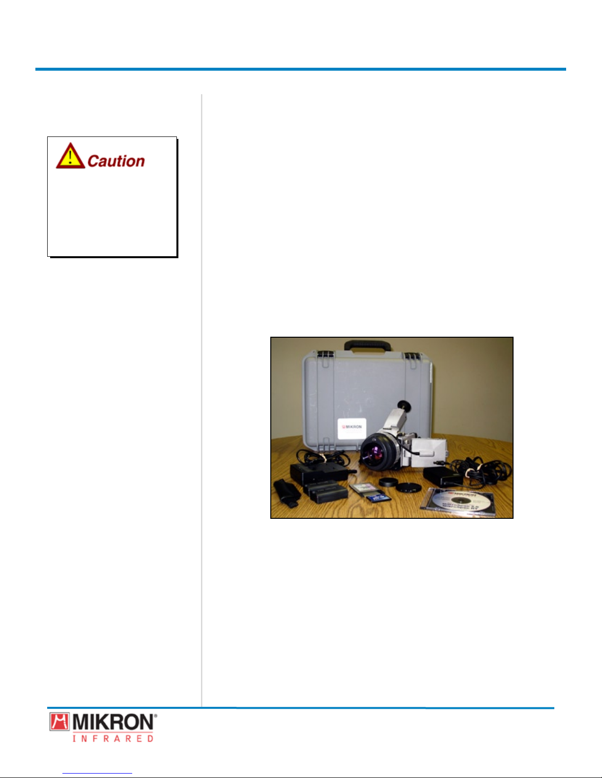
1.7 Unpacking and Inspection
The MikroScan 7600PRO thermal imaging camera is shipped in a rugged and padded
carrying case along with two battery packs, a battery charger, AC Adapter, memory
card, hand grip, lens cap and operating manual. A wide variety of optional accessories
are also available including battery belts and auxiliary lenses.
When unpacking and inspecting your camera, you need to do the following:
1) Check container contents against the shipping list.
2) Carefully unpack and inspect all components for visible damage.
3) Saveallpackingmaterials,includingthecarrier’sidentication
codes,untilyouhaveinspectedallcomponentsandndthatthere
is no obvious or hidden damage.
Before shipment, the camera was assembled, calibrated, and tested at the Mikron
Factory. If you note any damage or suspect damage, immediately contact the carrier and
Mikron.
MikroScan 7600PRO
5
Operator’s Manual
Catalog 11180-94
V15.4F 050406

Section 1
General Information
1.8 Procedure for Factory Repair and Return
Do not disassemble any Mikron instrument unless authorized by the factory.
Unauthorized disassembly will void your warranty. If the instrument malfunctions,
notify your local Mikron representative (or call 1-201-405-0900, or fax Mikron Service
Department at 1-201-405-0090). If necessary, they will authorize the return of your
instrument.
Pack the instrument in its original packing, or a carton with sufcient padding to
prevent further damage. Please include a note describing the problem (be specic) or
describe the services requested. Be sure to provide an approved purchase order number
even if the instrument is under warranty, the name and telephone number of the person
to contact should questions arise, and ship to the address below.
Within the United States, ship via United Parcel Service (UPS) to:
Mikron Infrared, Inc.
16 THORNTON ROAD
OAKLAND, NEW JERSEY 07436
U.S.A.
Shipping from outside the United States:
Please use a shipper such as UPS, FedEx or other established company. Do not ship by
mail. If shipping by UPS, or FedEx, please check the waybill box which states “Ship-
ping and Duty to be charged to Shipper.” Also state UPS or FedEx to clear customs.
Shipping documents must state in English “Goods originated in the USA being returned
temporarily for repairs.” If shipped by a company other than UPS or FedEx, address
shipment to Mikron Infrared, Inc. c/o Shenkers Custom Brokers. Failure to comply
with these instructions will result in U.S. Customs and Import duties being added to the
repair cost.
MikroScan 7600PRO
6
Operator’s Manual
Catalog 11180-94
V15.4F 050406

Section
2
Introduction
Mikron ikron has once again raised the bar on thermal imaging with the introduction
of the MikroScan 7600 PRO. This high resolution and high performance, hand-held
IR camera offers capabilities that far exceed any IR camera on the market today. The
MikroScan 7600PRO is an extremely lightweight, fully-radiometric camera with
built-in visual imaging capabilities. With its newly developed high-performance UFPA
detector and built-in visual camera, linking thermal and visual images and creating
thermal/visual image composites for easy data storage, analysis and post processing has
never been more efcient.
The MikroScan 7600 PRO is ergonomically designed for comfortable one-handed
point-and-shoot operation using simple joystick operation, an intuitive menu system,
ve direct access buttons, viewnder and highquality ip out LCD display. It includes
on-board digital voice recording and has the ability to simultaneously record high-de-
nition 14-bit thermal images with digital visual images.
It is battery operated, comes standard with extensive onboard image processing software, and has the ability to store images and data to a standard compact ash memory
card. Images can also be viewed in real-time via the video output or through a built-in
IEEE 1394 (Firewire®) interface. Completely self-contained in a dust proof and splash
proof case, the MikroScan 7600 PRO not only meets IP54 specications, but it also
offers a shock rating of 30G (IEC60068-2-27) and a vibration rating of 3G
(IEC60068-2-6), making it the perfect imager for the even the most extreme of environ-
ments.
2.1 System Overview
The MikroScan 7600PRO is a non-contact, high sensitivity infrared radiometer. It measures the infrared radiation emitted by the target surface and converts this radiation into
a two-dimensional image related to the temperature distribution at the target surface.
Through the use of standard on-board diagnostic software, the image can be used to
provide a picture of temperature variations over the area included in the eld of view, in
either temperature related colors or in black and white. Point temperatures can also be
derived from the image.
MikroScan 7600PRO
7
Operator’s Manual
Catalog 11180-94
V15.4F 050406
Section 2
Camera Features
Camera Features
(Front)
(Front)
Introduction
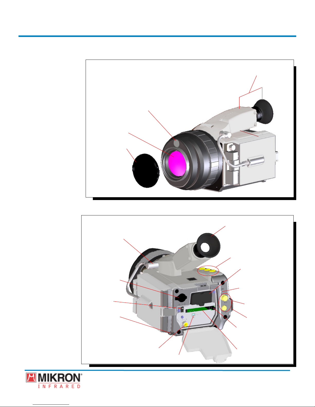
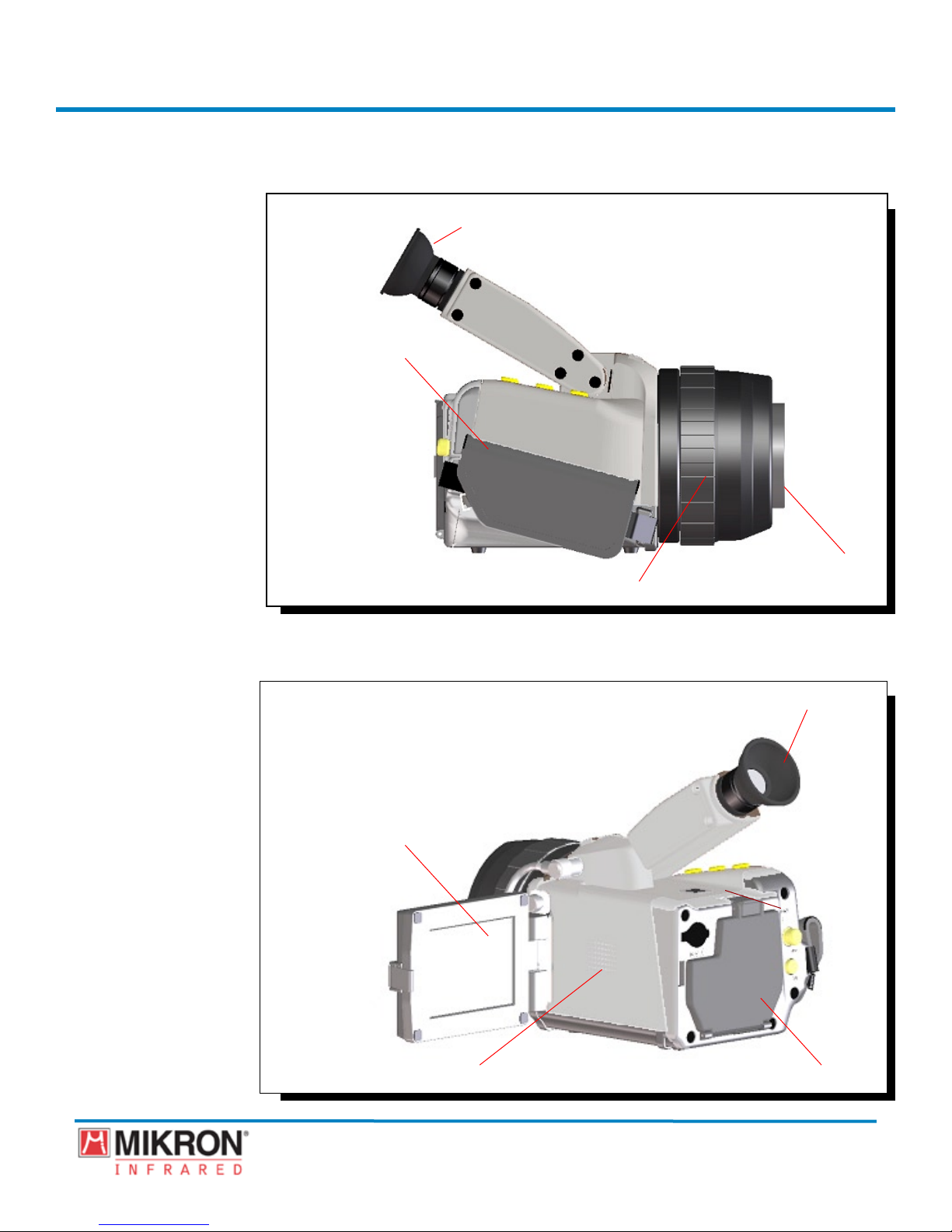
2.2 Construction
Electronic Viewfinder
CCD Window
Infrared Lens
Lens Protection Cap
Camera Features
Camera Features
(Back)
(Back)
Display Terminal
Terminal Cover
for AC Adapter
Power Switch
Grip Belt Hook
Video Output Terminal
IEEE1394 Interface
8
Viewfinder
Key Panel
Battery Compartment
Power LED
Key Panel
Grip Belt Hook
Removal Button for
Compact Flash Memory
Card
Compact Flash
Memory Card Slot
MikroScan 7600PRO
Operator’s Manual
Catalog 11180-94
V15.4F 050406
Section 2
Camera Features
(Side)
Introduction
2.2 Construction
Viewfinder
Hand Grip Belt
Camera Features
(Side)
Infrared Lens
Focusing Ring
Viewfinder
LCD Display
Microphone Speaker for Voice Memo Function
9
Rear Cover
MikroScan 7600PRO
Operator’s Manual
Catalog 11180-94
V15.4F 050406
Section 2
Introduction
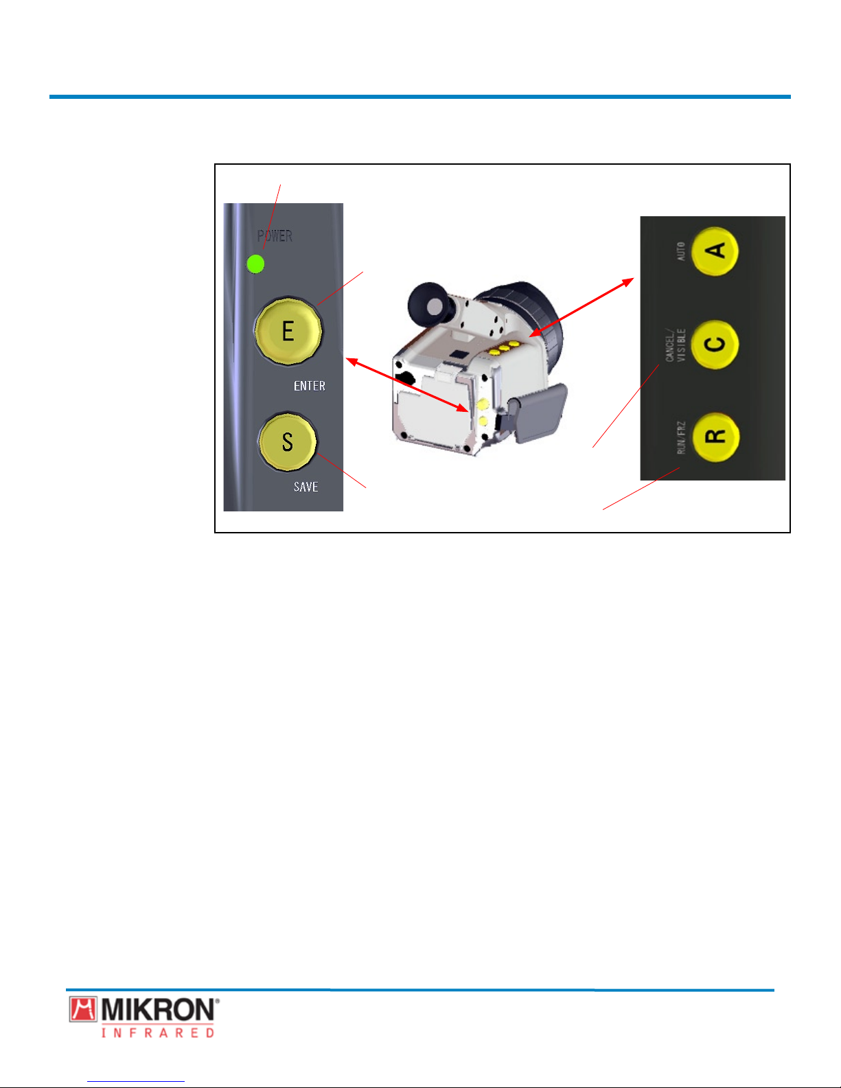
2.3 Key Panel Functions
[1] Power Indicator Light
[4] Auto
[2] Joystick/Enter
[5] Cancel/
Visible
[3] Save
[6] Run/Frz
Number Description Function
1 POWER Green light indicates that the camera is
switched on.
2 (E) JOYSTICK/ENTER Used to set certain menu functions. Also used
as a toggle key to move the cursor along the
horizontal plane of the display and/or the
vertical plane of the display, which allows
navigation through menus and selection of
certain options.
3 (S) SAVE Saves the current image data in either the
“run” or “freeze” modes.
4 (A) AUTO Automatically optimizes the focus, sensitivity,
and temperature level for the current display.
5 (C) CANCEL/VISIBLE Used to cancel out of certain menu functions.
Also used to display the visible light image.
6 (R) RUN/FRZ Places the instrument in the image and data
acquisition mode. Also used to “freeze” the
displayed image and data and certain menu
functions.
10
MikroScan 7600PRO
Operator’s Manual
Catalog 11180-94
V15.4F 050406
Section 2
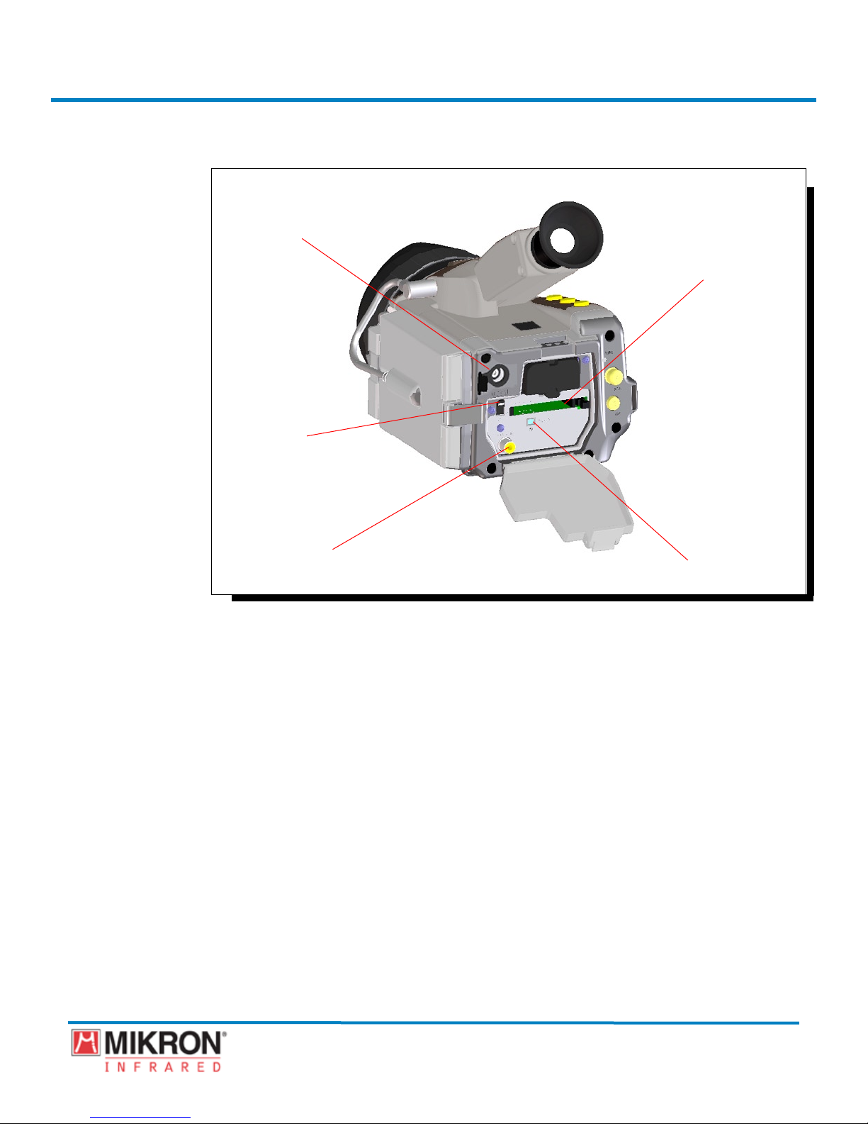
Display/Video
Output/AC Adapter
Terminals
Introduction
2.4 Camera Interfaces
AC Adapter Terminal
Memory Card Expansion Slot
Power Switch
Analog Composite Video
Output Connector
Feature Function
AC Adapter
Power Switch The power switch on the MikroScan
IEEE 1394 (Firewire) Interface The IEEE 1394 (Firewire) interface
Memory Card Expansion Slot Insert Compact Flash Memory Card for
Analog Composite Video Output Connector The Composite Video Output interface
IEEE 1394 (Firewire®) Interface
AC to DC power conversion is available
through the DC Power Entry Connector.
Input voltage is 6V DC with a current
draw of up to 3.5 amps.
7600PRO switches the camera between
two settings: ON and OFF.
allows remote camera control, image
capture, and process analysis using
software running on a Windows-based PC.
storage and retrieval of images.
allows transmission of analog video
signals over a cable to a monitor. This
allows video information to be carried
as a single signal in either NTSC or PAL
format.
11
MikroScan 7600PRO
Operator’s Manual
Catalog 11180-94
V15.4F 050406
Section 2
Introduction
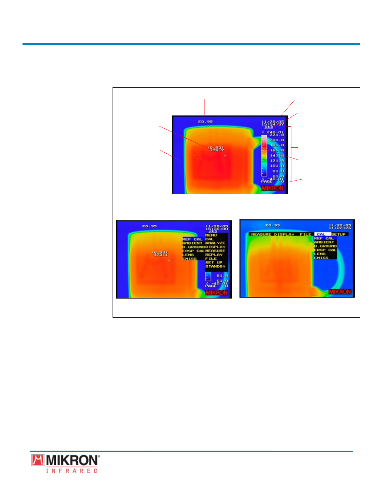
2.5 On Board Image Processing Software
MikroScan 7600PRO
Display Screens
Cursor Point
Image Display
Emissivity
Main Display--Run Mode
Date/Time
Run/Freeze Mode
Temperature Range
Color Palette Bar
Page
Main Display with Classic Type Menu
12
Main Display with Standard Type Menu
MikroScan 7600PRO
Operator’s Manual
Catalog 11180-94
V15.4F 050406
Section 2
Introduction
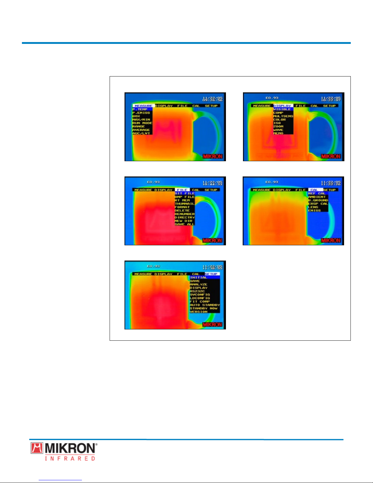
On Board Image Processing Software —Standard Type Menu
MikroScan 7600PRO
MikroScan 7600PRO
Display Screens—Standard
Display Screens—Standard
Type Menu
Type Menu
Main Display with Measure Sub-Menu
Main Display with File Sub-Menu Main Display with Cal Sub-Menu
Main Display with Setup Sub-Menu
Main Display with Display Sub-Menu
13
MikroScan 7600PRO
Operator’s Manual
Catalog 11180-94
V15.4F 050406
Section 2
Introduction
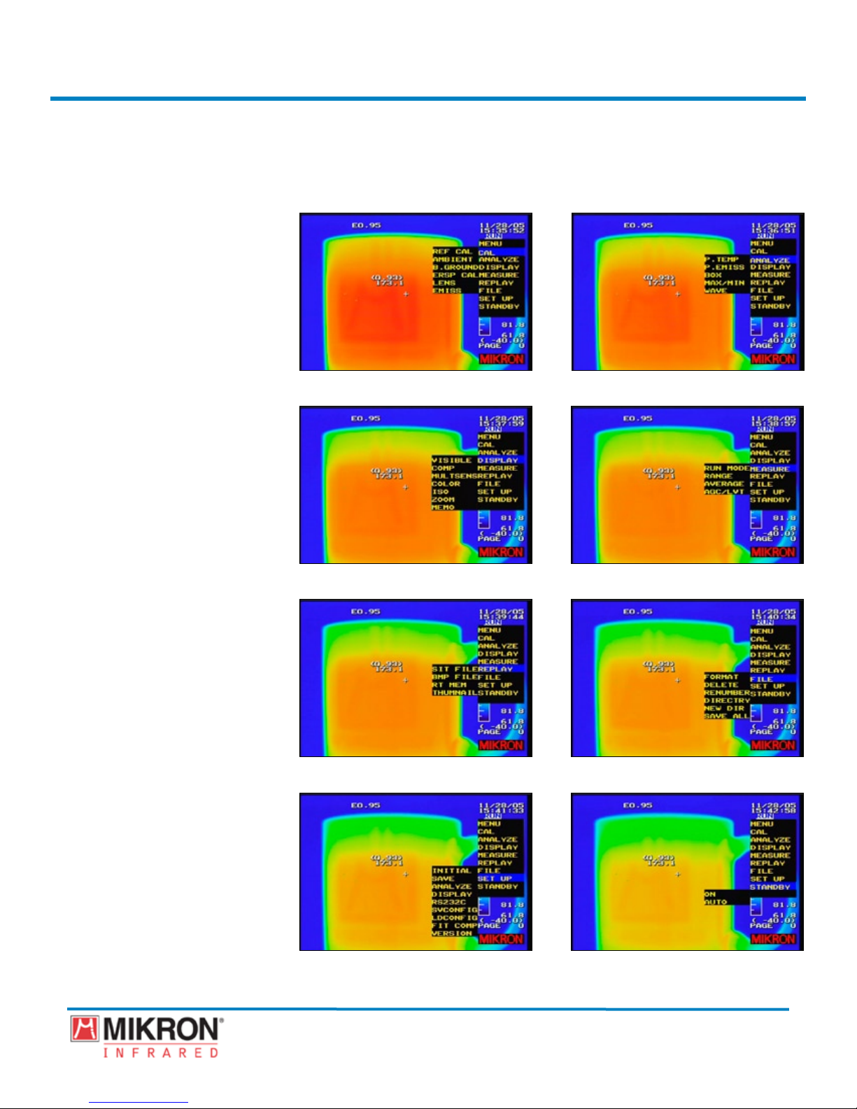
On Board Image Processing Software —Classic Type Menu
MikroScan 7600PRO
Display Screens—Classic Type
Menu
Main Display with Cal Sub-Menu
Main Display with Display Sub-Menu Main Display with Measure Sub-Menu
Main Display with Replay Sub-Menu Main Display with File Sub-Menu
Main Display with Analyze Sub-Menu
Main Display with Setup Sub-Menu Main Display with Standby Sub-Menu
MikroScan 7600PRO
14
Operator’s Manual
Catalog 11180-94
V15.4F 050406

Section 2
2.6 Camera Functions
Button Control Features
Feature Function
[RUN/FREEZE]
1)
[AUTO]
2)
[FOCUS]
3)
[LEVEL]
4)
[SENSITIVITY]
5)
[SPAN]
6)
[SAVE]
7)
[SWITCH DISPLAYED
8)
IMAGE]
Displays the image and image data in
“real-time”. Also used to “freeze” the
displayed image and data.
The MikroScan 7600PRO includes an
auto processing feature, which automatically focuses the camera and optimizes the
temperature level and sensitivity ranges
for the target being monitored.
Provides electronic focusing functionality.
Allows you to set the optimum temperature level.
Allows you to set the level of sensitivity.
Allows you to set the upper limit temperature value of the temperature scale.
Allows you to save the thermal image,
visual image, voice memo, and
annotations.
Allows you to switch between the thermal
image and visible light image.
Introduction
9)
10)
11)
[EMISSIVITY]
[BLACK AND WHITE VIEW]
[MENU]
The measuring temperature can be corrected by applying the emissivity of the
measured object in the emissivity setting. Emissivity for the correction can be
selected within the range of 0.10 to 1.00
with 0.01 steps. See Section 6.1 for more
information on Emissivity Settings.
Allows you to switch between a color
display and a monochrome display.
Allows you to select menu items
Main Menu Functions
Feature Function
1)
[MEASURE MENU]
a)
[POINT TEMP]
Allows you to establish certain settings for
various measurement conditions.
The MikroScan 7600PRO allows you
to establish up to ten points and view
the temperature data of these points at
selected locations anywhere within the
eld of view.
15
MikroScan 7600PRO
Operator’s Manual
Catalog 11180-94
V15.4F 050406

Section 2
Introduction
b)
c)
d)
e)
[POINT EMISS]
[BOX]
[MAX/MIN TEMP]
[OFF]
[MAX]
[MIN]
[MAX HOLD]
[MIN HOLD]
[RUN MODE]
[SAVE]
(OFF]
In addition to viewing point temperature
data, the MikroScan 7600PRO also allows
you to establish individual emissivity
values for one or more points and to
obtain information on how the temperatures of the various points are affected by
differences in emissivity settings.
Used to determine the Max, Min, and Avg.
temperatures within a specied area of a
thermal image. When creating a box on
a thermal image, the max, min, and avg.
temperatures within the area of the speci-
ed box are displayed.
By combining use of this function and
the function of dening a box, the temperatures within the specied area can be
tracked with the cursor.
Turns off the display of the maximum or
minimum temperature.
Displays the maximum temperature and
tracks it with the cursor.
Displays the minimum temperature and
tracks it with the cursor.
Displays the maximum temperature and
holds its value and the cursor position.
Displays the minimum temperature and
holds its value and the cursor position.
Used to detect when the temperature
on the thermal image goes out of the
specied temperature range. Also used for
periodically saving certain phenomenon to
a memory card and can also automatically
and periodically record thermal images.
See Section 5.5 for more information on
the Event
functions.
Allows certain phenomenon to be
periodically saved to a memory card.
Automatic saving is NOT performed.
(PC CARD]
(RTM]
[FREEZE]
16
Automatic saving is periodically
performed (note: the time interval is set in
the INTERVAL setting).
Automatic saving is periodically
performed (note: the time interval is set in
the INTERVAL setting).
Allows measurements to be frozen when
an event condition occurs.
MikroScan 7600PRO
Operator’s Manual
Catalog 11180-94
V15.4F 050406

Section 2
Introduction
(OFF]
(ON]
[ALARM MSG]
(OFF]
(ON]
[ALARM SOUND]
(OFF]
(ON]
[INTERVAL]
(5 TO ~3600
SECONDS
[EVENT]
[THRESHOLD
VALUE]
[UNDER]
The instrument will continue to operate in
run mode even when an event condition is
triggered.
The instrument will enter freeze mode as
soon as an event condition is triggered..
Displays a warning message when an
event condition occurs.
No alarm message will appear when the
event condition is triggered.
An alarm message of [OVER] or
[UNDER] will appear on the display when
the event condition is triggered.
Sounds an audible warning when an event
condition occurs.
There will be no audible sound when the
event condition is triggered.
An audible beep will be heard when the
event condition is triggered.
Species the time interval to be used for
automatically saving the thermal image to
the memory card..
The time interval can be specied by onesecond steps beginning at ve seconds.
Occurs as the result of a condition based
on the specied threshold temperature
within the thermal image.
This value is the specied temperature for
generating an event condition, and can be
specied within the specied temperature
range.
As the temperature decreases below the
threshold value, the event occurs. (This
determines an event condition based on
the maximum or minimum temperature
on a thermal image, unless the threshold
value is specied otherwise. When a BOX
setup is set, it judges using the maximum
or minimum temperature of the box within
the limits).
17
MikroScan 7600PRO
Operator’s Manual
Catalog 11180-94
V15.4F 050406

Section 2
Introduction
[OVER]
[DELAY]
(0 TO ~60
SECONDS
(0 TO ~100
FRAMES
(0 TO ~1664
FRAMES
[BOX]
[BOX]
[WHOLE]
[SAVE VISIBLE]
[OFF]
[IR LINK]
As the temperature rises above the threshold value, the event occurs. (This determines an event condition based on the
maximum or minimum temperature on a
thermal image, unless the threshold value
is specied otherwise. When a BOX setup
is set as from A to E, it judges using the
maximum or minimum temperature of the
box within the limits).
Species the time from the occurrence
of an event condition to the freezing of
measurements, or the number of frames
automatically saved to the memory card or
the internal memory.
The time from the occurrence of an event
condition to enter the freeze mode. (Note:
if SAVE is set to OFF, the measurements
will not be saved to the memory card or
the internal memory.
Species the number of frames to automatically record to the memory card
before the instrument enters freeze mode
(Note: the total number of frames saved
will be dependent upon the amount of
available space on the memory card)
Species the number of frames to automatically record to instruments internal
memory (RTM) before the instrument
enters freeze mode.
Allows box range areas on a thermal
image to be dened to determine event
conditions.
Allows you to specify a box range area on
the thermal image to determine the event
conditions.
When WHOLE is specied, event conditions are determined on the entire thermal
image.
Allows you to automatically link the visible light data with the thermal data when
saving an event to the memory card.
The instrument will only record the thermal image and image data when an event
condition is triggered.
The instrument will record to the memory
card, the visible light image along with
the thermal image and image data as a
single .sit le when an event condition is
triggered.
18
MikroScan 7600PRO
Operator’s Manual
Catalog 11180-94
V15.4F 050406

Section 2
Introduction
2)
f)
g)
h)
[DISPLAY MENU]
a)
b)
[RANGE]
[1]
[2]
[AVERAGE]
[GAIN CONTROL]
[OFF]
[LVT]
[AGC]
[VISIBLE IMAGE]
[COMPOSITE
IMAGE DISPLAY]
The MikroScan 7600PRO provides a total
of two temperature ranges. These two
ranges provide an overall temperature
span of -40°C to 500°C (-40°F to 932°F).
Range 1: -40°C to 120°C (-40°F to
248°F).
Range 2: 0°C to 500°C (32°F to 932°F).
The S/N Improvement function aids in
reducing the noise included in the image
signals by means of averaging the image.
See Section 4.9 for more information on
this function.
The Gain Control Feature is used for
performing automatic temperature or automatic sensitivity tracing. See
Section 4.10 for more information on the
Gain Control feature.
Disables the Gain Control Feature.
When LVT is active, the cross cursor
traces a point temperature signal and
always controls for the temperature signal
level to be at the center level of the color
bar. When the cross cursor is not used, the
temperature signal at the center (X=160,
Y=120) of the thermal image is traced.
While level trace is active the LVT is
displayed in the upper-right corner of the
screen.
When AGC is active, it traces the temperature signal of the entire thermal image and
always controls the display sensitivity and
temperature level to be at their optimal
values. By combining use of this mode
and the LEVEL/SENS gain mode of the
range mode, the temperature signal can be
traced beyond the range. When the auto
gain control is active, AGC is displayed in
the upper-right corner of the screen.
Allows you to establish certain display
options.
Allows you to display a visible image.
Creates a thermal/visual composite image.
19
MikroScan 7600PRO
Operator’s Manual
Catalog 11180-94
V15.4F 050406

Section 2
Introduction
c)
d)
[MULTISENSE]
[OFF]
[MIDDLE]
[HIGH/LOW]
[COLOR]
[COLOR POSI]
(256, 128, 64,
32, 16)
[COLOR NEGA]
(256, 128, 64,
32, 16)
[MONO POSI]
Adjusts the color palette to allow you to
focus on the details surrounding the center
temperature of the display or on the higher
and lower temperature regions on the
display..
No adjustments are made to the color
palette.
Adjusts the color palette to allow you to
focus on the details surrounding the center
temperature on the display.
Adjusts the color palette to allow you to
focus on the details surrounding the higher
and lower temperature regions on the
display.
Sets the color scale to be used for the
image display. The choices include, color
display, reverse color display, monochrome display, and reverse monochrome
display. Depending on the application, one
scale might be more suitable than another
for obtaining optimum results.
Reverse color settings (Shine, Fine,
Rainbow, Brightness, Hot Iron, Medical).
Used to select the desired number of
colors.
Reverse color settings (Shine, Fine,
Rainbow, Brightness, Hot Iron, Medical).
Used to select the desired number of
colors.
Monochrome settings.
e)
(256, 128, 64,
32, 16)
[MONO NEGA]
(256, 128, 64,
32, 16)
[ISOTHERMAL]
[BAND A]
[BAND B]
20
Used to select the desired number of
colors.
Reverse monochrome settings.
Used to select the desired number of
colors.
Isothermal bands can be set in the color
display. A maximum of four (4) isothermal bands can be set. Isothermal bands
can be set within the temperature range
of the color bar but not in full scale of the
Temperature Ranges 1 or 2. The Isothermal display is a very useful tool for noticing abnormal temperature areas on the
measuring object.
Isothermal Band.
Isothermal Band.
MikroScan 7600PRO
Operator’s Manual
Catalog 11180-94
V15.4F 050406

Section 2
Introduction
3)
5)
[BAND C]
[BAND D]
f)
g)
h)
[FILE MENU]
a)
b)
c)
d)
e)
f)
g)
h)
i)
j)
[CAL MENU]
a)
[ZOOM]
[WAVE]
[MEMO]
[SIT FILE]
[BMP FILE]
[RT MEM]
[THUMBNAIL)
[FORMAT]
[DELETE]
[RENUMBER]
[DIRECTORY]
[NEW DIR]
[SAVE ALL]
[REF CAL]
Isothermal Band.
Isothermal Band.
Sets the digital zoom (x2 and x4).
Displays the temperature distribution of
the cross cursor as a line prole..
Allows an operator to designate an
annotation on the display consisting of an
alpha-numeric combination and/or several
symbols..
Allows you to establish certain settings for
data storage and retrieval.
Replays a .SIT le.
Replays a .BMP le.
Replays a .frames stored in the camera’s
internal memory.
Displays multiple images of .SIT les on a
single display.
Allows you to delete all image les and
subdirectories from the CF card.
Deletes les contained in the root directory or subdirectories stored on the CF
card.
Renumber the les contained within the
various directories stored on the CF card.
The le numbers range from 0001 to
9999. More than 9999 triggers an error
message of FULL. After a le is deleted,
the deleted le number is absent. Therefore renumber the les in order from 0001.
Switches between the root directory or
subdirectories stored on the CF card.
Creates a subdirectory under the root
directory of the CF card.
Allows you to save data previously stored
in the camera’s internal memory to the CF
card.
Performs settings about adjustment processing.
Adjusts the detected temperature corresponding to the measurement environment.
21
MikroScan 7600PRO
Operator’s Manual
Catalog 11180-94
V15.4F 050406

Section 2
Introduction
b)
c)
c)
[AMBIENT]
[SETUP MODE]
[PARAM]
[VALUE]
[BACKGROUND]
[ERSP CAL]
The Ambient Compensation feature is
used for compensating the inuence of the
ambient up to the measurement object.
Used to select the desired ambient compensation mode.
The Parameter mode is used for inputting
the atmospheric temperature, the humidity, and the distance up to the measuring
object, getting the compensation value
from them, and then compensating the
measuring data.
The Value mode is used for inputting the
atmospheric temperature and the compen-
sation value, and the compensating the
measuring data with them.
The Background Compensation feature
is used to compensate for reectivity/
background errors.
Adjusts the detected temperature corresponding to the measurement environment.
4)
d)
e)
[SETUP MENU]
a)
[LENS]
[EMISS]
[INITIAL MENU)
[TEMP UNIT]
[°C]
[°F]
22
The MikroScan 7600PRO is shipped with
a standard lens offering a 27° (H) x 20.3°
(V) eld of view. It also supports additional lenses, which are available at the
time of purchase. When a lens is changed,
the instrument must be matched to the
new lens characteristics. Refer to your
lens documentation for more information
on working with the optional lenses.
Allows you to choose the correct
emissivity from a table of emissivity
values.
Allows you to establish certain user environment settings.
Performs initial settings for the camera..
Defines the desired temperature unit.
Used to display temperature in degrees
Celsius.
Used to display temperature in degrees
Fahrenheit.
MikroScan 7600PRO
Operator’s Manual
Catalog 11180-94
V15.4F 050406

Section 2
Introduction
[FILE NAME]
[AUTO MODE]
[FULL]
[FOCUS]
[LEVEL/
SENSITIVITY
OR
LEVEL/SPAN]
[LANGUAGE]
[IEEE 1394]
[ON]
[OFF]
[DATE FORMAT]
[YY/MM/DD]
[MM/DD/YY]
[DD/MM/YY]
[SET DATE]
[SET TIME]
[HH/MM/SS]
Used to specify the first four digits of
the file name as it is saved to the internal
memory card.
The AUTO MODE is used in conjunction with the auto formatting feature of
the MikroScan 7600PRO. This feature
automatically focuses the instrument and
optimizes the temperature and sensitivity
ranges for the target being monitored. See
Section 4.9 for more information on the
Auto Formatting functions.
Automatically sets the optimum values
for the focus position, sensitivity, and
temperature level. Full AUTO for LEVEL/
SENS/FOCUS (default value)
Automatically sets the optimum values
for the focus position utilizing the Focus
AUTO mode.
Automatically sets the optimum values for
the temperature level and sensitivity OR
the temperature level and span.
The various functions of the MikroScan
7600PRO can be displayed in a number
of different languages including English,
Japanese, German, French, Spanish, and
Portuguese.
Sets support option for IEEE 1394 connectivity.
IEEE1394 supported (default).
IEEE 1394 not supported.
Used to set the desired date format display
form.
Date is displayed by year, month, day
(default).
Date is displayed by month, day, year.
Date is displayed by day, month, year.
Used to set the date stamp which will be
displayed as yy/mm/dd, mm/dd/yy, or dd/
mm/yy as selected from the date format
menu.
Used to set the time stamp.
Time is displayed by hours, minutes,
seconds.
23
MikroScan 7600PRO
Operator’s Manual
Catalog 11180-94
V15.4F 050406

Section 2
Introduction
b)
c)
[DISPLAY TIME]
[TIME & DATE]
[DATE]
[TIME]
[OFF]
[OPERATION]
[STANDARD]
[CLASSIC]
[SAVE MENU)
[VOICE MEMO]
[ON]
[OFF]
[SAVE FORMAT]
[SIT]
[BMP]
[SAVE VISIBLE]
[ON]
[OFF]
[ANALYZE)
[POINT MODE]
Allows options for displaying date and/or
time.
Displays both date and time (default).
Displays only the date.
Displays only the time.
Neither the time nor date are displayed.
Allows you to choose between the standard menu structure and the classic menu
structure..
Provides navigational structure located at
top of display. (default).
Provides navigational structure along right
side of display.
Performs save settings for the camera.
Allows you to choose whether or not to
enable the voice annotation feature of the
MikroScan 7600PRO. .
This option enables the voice annotation
feature of the MikroScan 7600PRO..
This option disables the voice annotation feature of the MikroScan 7600PRO
(default).
Allows you to choose to save images in
either a .BMP or a .SIT format.
Images are saved in full 14-bit digital
format and include all data associated with
the image file.
Images are saved as bitmap images and do
not include data which may be essential
for future review and analysis. .
Allows you to save visible light images
with their associated infrared image.
Allows images to be saved and linked to
their associated infrared images
Visible light images can be viewed but not
saved.
Performs analysis settings for the camera..
The MikroScan 7600PRO allows you to
view the temperature data of one or more
points at selected locations anywhere
within the field of view. It also allows you
to obtain information on how the temperatures of the various points are affected by
differences in emissivity settings.
24
MikroScan 7600PRO
Operator’s Manual
Catalog 11180-94
V15.4F 050406

Section 2
Introduction
d)
[TEMP]
[TEMP &
EMISS]
[∆TEMP
EMISS]
[BOX TEMP]
[ON]
[OFF]
[DISPLAY MENU)
[NUC MODE]
]
[∆TEMP &
Displays the temperature of the points
under the color bar. Does not, however,
allow emissivity settings to be changed or
displayed.
Displays the temperature and emissivity
of each point near the point cursor. Also
allows emissivity of each point to be set
individually.
.
Displays the specified point temperature
under the color bar. Also displays the
temperature difference
A and point B. However, this mode does
∆
T between point
not allow the emissivity to be corrected on
an individual basis.
Displays the specified point temperature under the color bar and displays the
emissivity setting of the point near the
point cursor. Also displays the temperature
difference
B. However, the emissivity is displayed
∆
T between point A and point
only when the emissivity of the point is
different from the emissivity of the whole
screen.
Used to determine the Max, Min, and Avg.
temperatures within a specified area of a
thermal image. When creating a box on
a thermal image, the max, min, and avg.
temperatures within the area of the specified box are displayed.
The maximum, minimum, and average
temperature of the area defined by the box
is not displayed.
The maximum, minimum, and average
temperature of the area defined by the box
is displayed.
Performs screen display settings for the
camera.
Corrects uneven characteristics of the
Infrared detector elements (UFPA). Note:
the main unit internally has a reference
blackbody source, which has an even temperature surface. NUC operation corrects
the unevenness of characteristics for all
elements of UFPA by the reference blackbody source. Also an internal accurate
thermometer monitors the temperature of
the reference blackbody source and calibrates the unit during the NUC Operation.
25
MikroScan 7600PRO
Operator’s Manual
Catalog 11180-94
V15.4F 050406

Section 2
Introduction
[MANUAL]
[AUTO]
[SET L/S]
[LEVEL/
SENSITIVITY]
[LEVEL/SPAN
[FILTERING]
[ON]
[OFF]
[ALL CLEAR]
[ON]
[OFF]
[STATUS BAR]
[ON]
[OFF]
[COLOR BAR]
[ON]
[OFF]
NUC only works when changing to the
RUN mode. (default)
In AUTO, interval time is displayed. Interval time is set from 1 minute to 24 hours.
Allows you to make adjustments based
on the level & sensitivity OR the level &
span.
Sets the intervals of the temperature color
bar scale. (default)
Sets the upper limit temperature value of
the color bar. Note: When the mode is set
to Level & Span, changes cannot be made
to the sensitivity settings..
Allows an additional level of image
smoothing to a thermal image while the
instrument is in Freeze mode.
Displays the corrected image by spatial
filter on FREEZE (default)
The spatial filter correction is not performed.
Allows you to focus solely on the image
by hiding all display elements other than
the logo.
All display elements are visible such as
color bar, temperature scale, date, time,
etc. (default).
All display elements are hidden other than
the logo.
Allows you to focus solely on a greater
portion of the image by hiding all status
bar elements on the display.
All status bar elements are visible such as
battery level, emissivity value, date, time,
etc. (default)
All status bar elements are hidden.
Allows you to choose whether or not to
display the color bar.
This option enables the display of the
color bar (default).
This option disables the display of the
color bar.
26
MikroScan 7600PRO
Operator’s Manual
Catalog 11180-94
V15.4F 050406

Section 2
Introduction
e)
f)
g)
h)
i)
j)
k)
[BATTERY]
[ON]
[OFF]
[TV SYSTEM]
[NTSC]
[PAL]
[TV SCAN]
[NON INTERLACE]
[INTERLACE]
[LCD BRIGHT]
[RS232C)
[RS-232C
BAUD RATE]
[RS-232C
FORMAT]
[SVCONFIG]
[LDCONFIG]
[FIT COMPOSITE
IMAGE]
[AUTO STANDBY]
[STANDBY NOW]
[VERSION)
Allows you to choose whether or not
to display the battery power indication
symbol.
This option enables the display of the battery power indication symbol (default).
This option disables the display of the battery power indication symbol.
This option is used to select the desired
composite video output mode.
Used to select the 60-Hz American Standard (NTSC) video output option.
Used to select the 50-Hz European Standard (PAL) video output option.
This option is used to select the desired
TV Scan format
Used to select the non-interlace option.
Used to select the interlace option.
Sets the brightness level of the LCD
display.
Performs RS-232C communications settings for the camera.
Utilized in conjunction with the
RS-232C interface.
Used to select the 50-Hz European Standard (PAL) video output option.
Saves environmental settings.
Loads Saved environmental settings.
Adjust the position of the thermal to the
visible image when a composite image is
displayed.
Allows you to set the camera to automatically enter standby mode based on a preestablished time interval.
Allows you place the camera in standby
mode.
Displays information pertaining to the
camera’s firmware version.
27
MikroScan 7600PRO
Operator’s Manual
Catalog 11180-94
V15.4F 050406

Section 2
Introduction
2.7 Standard Camera Accessories
AC Adapter
Battery Charger
(2) Battery Packs
Neck Strap
Lens Protection Cap
28
MikroScan 7600PRO
Operator’s Manual
Catalog 11180-94
V15.4F 050406

Section
3
NOTE:
NOTE:
• Store battery packs
• Store battery packs
in a cool, dark loca-
in a cool, dark location when not in use.
tion when not in use.
• Recharge the battery
• Recharge the battery
pack every 6 months
pack every 6 months
when in storage.
when in storage.
Also recharge before
Also recharge before
and after every use.
and after every use.
Getting Started
3.1 Charging the Batteries
Your MikroScan 7600PRO was supplied with two Lithium Ion (Li-ion) Batteries. When
fully charged, each battery should provide approximately 110 minutes of continuous
operating use. Because these batteries have been shipped from the Mikron Factory with
a minimal charge, they will need to be fully charged before use.
Step 1 Step 2
Step 3 Step 4
NOTE:
NOTE:
If the charger has been
If the charger has been
connected to the power
connected to the power
supply before placing
supply before placing
the battery packs into
the battery packs into
position, the charging
position, the charging
pattern will not be posi-
pattern will not be position dependent. That
tion dependent. That
is, the first battery to
is, the first battery to
be inserted will begin
be inserted will begin
charging regardless of
charging regardless of
the position it holds.
the position it holds.
Once that battery is
Once that battery is
fully charged, the sec-
fully charged, the second battery will begin
ond battery will begin
charging.
charging.
1) Plug the battery charger power cord into a standard wall outlet.
2) Position one battery pack on the battery charger by aligning the
brackets and terminal ports on the battery pack to those on the
charger.
3) Press down on the battery pack while sliding it forward into
position.
4) Repeat steps 2 and 3 for the second battery pack.
Charging time is approximately 100 minutes per battery.
MikroScan 7600PRO
29
Operator’s Manual
Catalog 11180-94
V15.4F 050406

Section 3
NOTE:
NOTE:
If the battery
If the battery
temperature is lower
temperature is lower
than -10°C ±3°C or
than -10°C ±3°C or
higher than 60°C ±3°C,
higher than 60°C ±3°C,
the charger goes into a
the charger goes into a
standby mode and the
standby mode and the
charging lamps will
charging lamps will
continue to flash green
continue to flash green
for 120 minutes. After
for 120 minutes. After
120 minutes, the charg-
120 minutes, the charging lights turn off.
ing lights turn off.
Getting Started
3.1 Charging the Batteries (continued)
The battery charger has one red “Power On” lamp and two green “Charging” lamps.
The charging indicator lights indicate the charger assembly status as listed below:
Color Status Notes
Green, Flashing Charging Flashes green ‘on’ and ‘off’
Charging Lamp 2
Power Lamp
Charging Lamp 1
Green Full Charge Indicator light will remain
Black Error Charging lights will turn off
at 1 Hz while in the charging
mode.
green once the battery pack
has been fully charged.
if an error has been detected.
3.2 Connecting the Power Supply
Although there are several optional power supply accessories available for your
MikroScan 7600PRO, the standard power supply options supplied with your camera
include the AC Adapter and two battery packs. This section will cover the steps necessary for using these standard power supply options.
3.2.1 Before You Begin
Before applying any power source to your MikroScan 7600PRO, it is important that the
power switch on the camera be in the off position.
Step 1 Step 2
I = on position
O = off position
1) Open the hatch cover on the back of the camera.
2) Verify that power switch is in the off position as indicated in the
gureabove.
30
MikroScan 7600PRO
Operator’s Manual
Catalog 11180-94
V15.4F 050406

Section 3
Getting Started
3.2.2 Attaching the Battery Pack
Before attaching the battery pack to your MikroScan 7600PRO, it is important that the
power switch on the camera be in the off position.
Step 1 Step 2 Step 3
1) Open the terminal cover.
2) Position the fully-charged battery pack over the latch on the
terminal side of the camera as indicated by the arrow in Step 2
above.
NOTE:
NOTE:
The AC Adapter only
The AC Adapter only
provides power to the
provides power to the
camera; it does not
camera; it does not
charge the battery.
charge the battery.
When the AC Adapter
When the AC Adapter
and battery are
and battery are
connected at the same
connected at the same
time, the camera
time, the camera
receives its power from
receives its power from
the AC Adapter, not the
the AC Adapter, not the
battery.
battery.
3) Push the battery pack forward until it snaps into position as
indicated in Step 3 above.
3.2.3 Connecting the AC Adapter
Before connecting the AC Adapter to your MikroScan 7600PRO, it is important that the
power switch on the camera be in the off position.
Step 1 Step 2
1) Open the terminal cover on the camera.
2) Connect the DC connector of the AC Adapter to the DC input
connector on the camera.
Step 3
DC connector
AC connector
3) Plug the AC power cord into a standard wall outlet.
31
MikroScan 7600PRO
Operator’s Manual
Catalog 11180-94
V15.4F 050406

Section 3
When camera opera-
When camera operation has been completed,
tion has been completed,
always attach the lens
always attach the lens
protection cap to protect
protection cap to protect
the lens from damage.
the lens from damage.
Getting Started
3.3 Handling the Lens Protection Cap
Your MikroScan 7600PRO was shipped with a lens protection cap which was designed
specically for the MikroScan 7600PRO. The lens protection cap not only offers protection to the camera lens, but it can also be used for performing a reference calibration of
the camera (See Section 6.5.2 for more information regarding on calibrating the instrument).
3.3.1 Removing the Lens Cap
1) Squeeze the clips on both side of the lens cap.
2) Pull the lens protection cap off of the camera lens.
3.3.2 Attaching the Lens Cap
1) Position the lens protection cap over the camera lens with the
clips aligned horizontally to the camera.
2) Squeeze the clips on both sides of the lens cap and place over the
camera lens.
3) Release the clips and verify that the lens protection cap is secure.
32
MikroScan 7600PRO
Operator’s Manual
Catalog 11180-94
V15.4F 050406

Section 3
NOTE:
NOTE:
See Section 5.4 for informa-
See Section 5.4 for information on Using the Memory
tion on Using the Memory
Card Management Options.
Card Management Options.
Getting Started
3.4 Handling the Memory Card
Your MikroScan 7600PRO was shipped with a Compact Flash Memory Card which is
used for storing images and image data. A Compact Flash Adapter was also supplied to
provide transfer of images through a PCMCIA card slot in your laptop computer or
through a Card Reader attached to your personal computer. This section provides
information on installing the memory card into the MikroScan 7600PRO.
Before inserting or removing the memory card, it is important that the power switch on
the camera be in the off position.
3.4.1 Inserting the Memory Card
1) Remove the memory card from the Compact Flash Adapter.
2) Turn the memory card so that the connecting pins are vertically
aligned with the Memory Card Expansion Slot on the Camera.
3) Insert the memory card until you hear a click.
3.4.2 Removing the Memory Card
1) Push the release button located at the bottom of the Memory
Card Expansion Slot to release the memory card.
2) Pull the memory card from the camera.
3) Insert the memory card into the Compact Flash Adapter.
33
MikroScan 7600PRO
Operator’s Manual
Catalog 11180-94
V15.4F 050406

Section 3
NOTE:
When the camera is
powered on, the display
is automatically placed
in run mode.
Getting Started
3.5 Viewing Your First Image
1) Connect the power supply as described in Section 3.2 of this
manual.
2) Open the interface hatch cover on the back of the camera.
3) Insert the memory card or attach the appropriate cable to the
com serial port connector for video and data capture.
4) Move the power switch to the on position.
5) Remove the lens cover.
I = on position
O = off position
Once the power switch has been turned on, the camera will enter an
initialization mode. During initialization, a display will appear show-
ing the software
version, the color palette bar, and the progress of the
system check in the form of a blue dotted line.
Camera Software Version
System Check
Initialization in Progress
Once the initialization process has been completed, the camera
enters the run mode and the display changes to show additional
information on the various camera settings as well as the scene
towards which the camera is pointed.
Palette Bar
34
MikroScan 7600PRO
Operator’s Manual
Catalog 11180-94
V15.4F 050406

Section 3
Getting Started
3.6 Accessing the MikroScan 7600PRO Expanded
Menu Functions
Your MikroScan 7600PRO provides two types of menu structures which allow you
to navigate through the various camera options. The rst is the Standard Type menu
option, which provides the navigational structure located at the top of the display. The
second is the Classic Type menu option which provides the navigational structure along
the right side of the display.
To access the menu functions of the 7600PRO, you will be working with the JOYSTICK
and the JOYSTICK [E] BUTTON:
NOTE:
NOTE:
The particular menu
The particular menu
structure that will be
structure that will be
displayed is depen-
displayed is dependent upon the type of
dent upon the type of
operation selected in
operation selected in
the Initial Setup menu.
the Initial Setup menu.
See section 3.9.1.10
See section 3.9.1.10
for more information
for more information
on setting the type of
on setting the type of
menu structure.
menu structure.
JOYSTICK [E] BUTTON AND
FUNCTIONALITY
3.6.1 Using the Standard Type Navigational Structure
1) Press the JOYSTICK [E] button gain access to the 7600PRO standard
type menu.
2) Toggle the JOYSTICK to the left or right as needed until the desired
menu category appears with its pull-down menu.
[MENU CATEGORY HIGHLIGHTED]
35
MikroScan 7600PRO
Operator’s Manual
Catalog 11180-94
V15.4F 050406

Section 3
Getting Started
3) Toggle the JOYSTICK up or down as needed to highlight the desired
main-menu choice.
[MAIN MENU CHOICE HIGHLIGHTED]
4) Press the JOYSTICK [E] button to select the menu option.
OR
Press the CANCEL/VISIBLE button to cancel out of the menu mode
and to return to the main display.
NOTE:
NOTE:
The particular menu
The particular menu
structure that will be
structure that will be
displayed is depen-
displayed is dependent upon the type of
dent upon the type of
operation selected in
operation selected in
the Initial Setup menu.
the Initial Setup menu.
See section 3.9.1.10
See section 3.9.1.10
for more information
for more information
on setting the type of
on setting the type of
menu structure.
menu structure.
3.6.2 Using the Classic Type Navigational Structure
1) Press the JOYSTICK [E] button to lock the display and gain access to
the 7600PRO classic type menu.
2) Toggle the JOYSTICK button to the left or right until the [MENU]
option becomes highlighted at the top right hand corner of the dis-
play.
[MENU HIGHLIGHTED]
36
MikroScan 7600PRO
Operator’s Manual
Catalog 11180-94
V15.4F 050406

Section 3
Getting Started
3) Toggle the JOYSTICK button down to expose the drop-down list of
menu functions.
[MENU LIST EXPOSED]
4) Toggle the JOYSTICK button up or down as needed to highlight the
desired main menu choices.
[MAIN MENU CHOICE HIGHLIGHTED]
5) Toggle the JOYSTICK button to the left to highlight the sub-menu
choices.
[SUB-MENU CHOICE HIGHLIGHTED]
MikroScan 7600PRO
37
Operator’s Manual
Catalog 11180-94
V15.4F 050406

Section 3
Do not use excessive force
Do not use excessive force
when opening, closing, or
when opening, closing, or
tilting the LCD Display.
tilting the LCD Display.
Make sure the LCD display
Make sure the LCD display
is securely latched when
is securely latched when
the MikroScan 7600PRO.
the MikroScan 7600PRO.
is not in use.
is not in use.
Getting Started
6) Toggle the JOYSTICK button up or down as needed to highlight the
desired sub-menu choice.
[SUB-MENU CHOICE HIGHLIGHTED]
7) Press the JOYSTICK [E] button to select the menu option.
OR
Press the CANCEL/VISIBLE button to cancel out of the menu mode
and to return to the main display.
NOTE:
NOTE:
The device automatically
The device automatically
switches between the LCD
switches between the LCD
mode and the viewfinder
mode and the viewfinder
mode by simply open-
mode by simply opening and closing the LCD
ing and closing the LCD
display.
display.
NOTE:
NOTE:
See Section 7.1 of this
See Section 7.1 of this
manual for information on
manual for information on
working with External LCD
working with External LCD
Displays.
Displays.
3.7 Working with the LCD Display
The MikroScan 7600PRO allows you to view images through the viewnder or on the
ip-out LCD display. The camera is supplied with an autoswitch function which will
allow you to automatically switch between the LCD mode and the viewnder mode
simply by opening and closing the LCD display.
Step 1 Step 2 Step 3
1) Unlatch the LCD Display hook in the direction of the arrow as
shown in Step 1 above.
2) Open the LCD Display in the direction of the arrow as shown in
Step 2 above.
3) Tilt the LCD display as needed to adjust for proper viewing as
shown by the arrows in Step 3 above.
38
MikroScan 7600PRO
Operator’s Manual
Catalog 11180-94
V15.4F 050406

Section 3
Getting Started
3.8 Selecting a Lens Option
The MikroScan 7600PRO supports a lens with a 30.1°(H) x
22.7°(V) FOV, which is provided as a standard feature. It also supports additional lenses, which are available at the time of purchase.
When a lens is changed, the instrument must be matched to the new
lens characteristics. The lens option is changed as follows:
1) Verify the camera is operating in [RUN] mode.
2) Go to [MENU] → [CAL] → [LENS].
NOTE:
NOTE:
Refer to your lens docu-
Refer to your lens documentation for selecting the
mentation for selecting the
appropriate lens option.
appropriate lens option.
[LENS HIGHLIGHTED]
Standard View Menu
[LENS HIGHLIGHTED]
Classic View Menu
3) Press the JOYSTICK [E] button to select the LENS option.
[LENS OPTION SELECTED]
A bar will appear at the bottom of the screen showing the
current lens option:
4) Toggle the JOYSTICK up or down if needed until the desired option
has been selected.
MikroScan 7600PRO
39
Operator’s Manual
Catalog 11180-94
V15.4F 050406

Section 3
The options are:
• AUTO (Default)
• OPTION A *
• OPTION B *
*refer to your lens documentation for selecting the appropriate
setting
• OPTION C *
• OPTION D *
• OPTION E *
• OPTION F *
• OPTION G *
5) Press the JOYSTICK [E] button to save the setting and to return to
the main display
OR
Press the CANCEL/VISIBLE button to cancel out of the menu mode
and to return to the main display.
3.9 Customizing your MikroScan 7600PRO
Getting Started
The MikroScan 7600PRO provides environment setup options,
which allow you to setup, change, save and recall different camera
congurations based on your selections.
3.9.1 Establishing the Initial Setup Values
3.9.1.1 Selecting the Temperature Unit
The temperature scale is displayed on the right-hand side of the
display screen next to the color palette bar. The scale shows how
the temperature levels and their associated colors are distributed
throughout the image displayed. The high end of the temperature
range is shown at the top of the scale and the low end of the temperature range is shown at the bottom of the scale.
The temperature range can be displayed in degrees Celsius or
degrees Fahrenheit.
40
MikroScan 7600PRO
Operator’s Manual
Catalog 11180-94
V15.4F 050406

Section 3
Getting Started
The temperature unit can be selected as follows:
1) Go to [MENU] → [SET UP] → [INITIAL].
[INITIAL HIGHLIGHTED]
Standard View Menu
[INITIAL HIGHLIGHTED]
Classic View Menu
2) Press the JOYSTICK [E] button to gain access to the INITIAL SET UP
Menu.
3) Toggle the JOYSTICK up or down if needed to highlight [TEMP
UNIT]
.
[TEMP UNIT HIGHLIGHTED]
4) Toggle the JOYSTICK to the right to highlight the TEMP UNIT
option.
[TEMP UNIT OPTION HIGHLIGHTED]
MikroScan 7600PRO
41
Operator’s Manual
Catalog 11180-94
V15.4F 050406

Section 3
NOTE:
NOTE:
See Section 5 of this manual
See Section 5 of this manual
for more information on
for more information on
Working with Images and
Working with Images and
Image Files.
Image Files.
5) Toggle the JOYSTICK up or down as needed to select the desired
temp unit option.
The temp unit options are:
• °C (Default)
• °F
6) Press the JOYSTICK [E] button to save the setting and to return to
the main display.
3.9.1.2 Customizing the Memory Card File Name
The MikroScan 7600PRO stores images and image data to the
memory card using a pre-dened naming convention. As such, each
eleven character le name is made up of the following components.
TH91 0001 SIT
Getting Started
4 Character
Customizable
File Name
4 Digit Auto
Assigned
Number
3 Character
File Format
Extension
The rst four characters designate the le name. This le name can
be customized according to your particular needs.
To establish a new four-character le name prex:
1) Go to [MENU] → [SET UP] → [INITIAL].
[INITIAL HIGHLIGHTED]
Standard View Menu
[INITIAL HIGHLIGHTED]
2) Press the JOYSTICK [E] button to gain access to the INITIAL SET UP
Menu.
Classic View Menu
42
MikroScan 7600PRO
Operator’s Manual
Catalog 11180-94
V15.4F 050406

Section 3
Getting Started
3) Toggle the JOYSTICK up or down if needed to highlight [FILE
NAME]
.
[FILE NAME HIGHLIGHTED]
4) Toggle the JOYSTICKtotherighttohighlighttherstcharacterof
thelename.
[FILE NAME CHARACTER
HIGHLIGHTED]
5) Toggle the JOYSTICK up or down as needed to scroll through the
characters to select a letter in the A-Z range or a number in the 0-9
range.
[FILE NAME CHARACTER CHANGED]
MikroScan 7600PRO
43
Operator’s Manual
Catalog 11180-94
V15.4F 050406

Section 3
Getting Started
6) Toggle the JOYSTICK to the right to highlight the next character of
thelename.
[FILE NAME CHARACTER
HIGHLIGHTED]
7) Repeat steps 5 and 6 until you have selected and/or changed all the
desiredlenamevalues.
[FILE NAME CHARACTERS CHANGED]
8) Press the JOYSTICK [E] button to save the setting and to return to
the main display.
MikroScan 7600PRO
44
Operator’s Manual
Catalog 11180-94
V15.4F 050406

Section 3
NOTE:
NOTE:
See Section 4.10 of this
See Section 4.10 of this
manual for more informa-
manual for more information on Using the Auto
tion on Using the Auto
Processing Functions.
Processing Functions.
Getting Started
3.9.1.3 Setting the Auto Mode Function
The MikroScan 7600PRO includes an auto processing feature which
automatically focuses the instrument and optimizes the temperature
level and sensitivity OR temperature level and span for the target
being monitored.
The three available AUTO settings are as follows
Feature Function
FULL AUTO
Automatically sets the optimum values for the
focus position, sensitivity or span, and temperature level
AUTO FOCUS
Automatically sets the optimum values for the
focus position
LEVEL & SENS
(LEVEL & SPAN)
Automatically sets the optimum values for the
temperature level and sensitivity OR the temperature level and span.
Note: Whether the Auto Mode function affects the Level & Span
OR the Level & Sensitivity is determined by the L/S option that is
selected in display setup menu. See Section 3.9.4.2 for more information on selecting the desired L/S option.
To set the auto mode function:
1) Go to [MENU] → [SET UP] → [INITIAL].
[INITIAL HIGHLIGHTED] [INITIAL HIGHLIGHTED]
Standard View Menu
2) Press the JOYSTICK [E] button to gain access to the INITIAL SET UP
Menu.
Classic View Menu
45
MikroScan 7600PRO
Operator’s Manual
Catalog 11180-94
V15.4F 050406

Section 3
Getting Started
3) Toggle the JOYSTICK up or down if needed to highlight [AUTO
MODE]
.
[AUTO MODE HIGHLIGHTED]
4) Toggle the JOYSTICK to the right to highlight the auto mode option.
[AUTO MODE OPTION HIGHLIGHTED]
5) Toggle the JOYSTICK up or down as needed to select the desired
auto mode option.
The auto mode options are:
• FULL (DEFAULT)
• FOCUS
• LEVEL & SENSE or (LEVEL & SPAN)
6) Press the JOYSTICK [E] button to lock the setting and to return to
the main display.
46
MikroScan 7600PRO
Operator’s Manual
Catalog 11180-94
V15.4F 050406

Section 3
Getting Started
3.9.1.4 Setting the Language
The various functions of the MikroScan 7600PRO can be displayed
in a number of different languages including English, Japanese,
Portuguese, Spanish, French, German, Traditional Chinese, Chinese,
Korean, Russian, and Italian.
To set the language:
1) Go to [MENU] → [SET UP] → [INITIAL].
[INITIAL HIGHLIGHTED]
Standard View Menu
[INITIAL HIGHLIGHTED]
Classic View Menu
2) Press the JOYSTICK [E] button to gain access to the INITIAL SET UP
Menu.
3) Toggle the JOYSTICK up or down if needed to highlight
[LANGUAGE].
[LANGUAGE HIGHLIGHTED]
47
MikroScan 7600PRO
Operator’s Manual
Catalog 11180-94
V15.4F 050406

Section 3
NOTE:
NOTE:
See Working with Commu-
See Working with Communication Interfaces found in
nication Interfaces found in
Section 7.3 of this manual
Section 7.3 of this manual
for more information on
for more information on
setting up the IEEE 1394
setting up the IEEE 1394
(Firewire®) feature of this
(Firewire®) feature of this
camera.
camera.
4) Toggle the JOYSTICK to the right to highlight the LANGUAGE
option.
[LANGUAGE OPTION HIGHLIGHTED]
5) Toggle the JOYSTICK up or down as needed to select the desired
LANGUAGE option.
The language options are:
• ENGLISH (Default)
• JAPANESE
• PORTUGUESE
• SPANISH
• FRENCH
• GERMAN
• TRADITIONAL CHINESE
• CHINESE
• KOREAN
• RUSSIAN
• ITALIAN
6) Press the JOYSTICK [E] button to save the setting and to return to
the main display.
3.9.1.5 Activating the IEEE 1394 Functionality
Getting Started
The IEEE 1394 (Firewire®) feature of the MikroScan 7600PRO
provides remote camera control functionality and real-time data
acquisition and analysis through the IEEE 1394 interface.
See Working with Communication Interfaces found in Section 7.3
of this manual for more information on setting up the IEEE 1394
(Firewire®) feature of this camera.
3.9.1.6 Setting the Date Format
The date and time function of the MikroScan 7600PRO sets the
internal clock for the camera. The date and time is saved as part of
the image le and can be viewed on the display.
MikroScan 7600PRO
48
Operator’s Manual
Catalog 11180-94
V15.4F 050406

Section 3
To set the date format:
1) Go to [MENU] → [SET UP] → [INITIAL].
[INITIAL HIGHLIGHTED]
Getting Started
[INITIAL HIGHLIGHTED]
Standard View Menu
Classic View Menu
2) Press the JOYSTICK [E] button to gain access to the INITIAL SET UP
Menu.
3) Toggle the JOYSTICK up or down as needed to highlight [DATE
FORMAT]
.
[DATE FORMAT HIGHLIGHTED]
4) Toggle the JOYSTICK to the right to highlight the DATE FORMAT
option.
[DATE FORMAT OPTION HIGHLIGHTED]
49
MikroScan 7600PRO
Operator’s Manual
Catalog 11180-94
V15.4F 050406

Section 3
5) Toggle the JOYSTICK up or down as needed to change the DATE
FORMAT option.
The date format options are:
• YY/MM/DD: (year, month, day) [Default]
• MM/DD/YY: (month, day, year)
• DD/MM/YY: (day, month, year)
6) Press the JOYSTICK [E] button to save the setting and to return to
the main display.
3.9.1.7 Setting the Date
1) Go to [MENU] → [SET UP] → [INITIAL].
Getting Started
[INITIAL HIGHLIGHTED] [INITIAL HIGHLIGHTED]
Standard View Menu
Classic View Menu
2) Press the JOYSTICK [E] button to gain access to the INITIAL SET UP
Menu.
3) Toggle the JOYSTICK up or down as needed to highlight [SET
DATE]
.
[SET DATE HIGHLIGHTED]
50
MikroScan 7600PRO
Operator’s Manual
Catalog 11180-94
V15.4F 050406

Section 3
Getting Started
4) Toggle the JOYSTICKtotherighttohighlighttherstsetof
variables.
[DATE VARIABLE SELECTED]
5) Toggle the JOYSTICK up or down as needed to increase or decrease
the numeric value of the selected variable.
The variable options are dependent upon the date format setting
(See Section 3.9.1.6 of this manual).
The variable options appear in the following order:
• YY/MM/DD: (year, month, day) [Default]
• MM/DD/YY: (month, day, year)
• DD/MM/YY: (day, month, year)
6) Toggle the JOYSTICK to the right to highlight the next set of
variables.
7) Repeat steps 5 and 6 above to set the remaining variables.
8) Press the JOYSTICK [E] button to save the setting and to return to
the main display.
3.9.1.8 Setting the Time
1) Go to [MENU] → [SET UP] → [INITIAL].
[INITIAL HIGHLIGHTED] [INITIAL HIGHLIGHTED]
Standard View Menu
51
Classic View Menu
MikroScan 7600PRO
Operator’s Manual
Catalog 11180-94
V15.4F 050406

Section 3
Getting Started
2) Press the JOYSTICK [E] button to gain access to the INITIAL SET UP
Menu.
3) Toggle the JOYSTICK up or down as needed to highlight [SET TIME].
[SET TIME HIGHLIGHTED]
4) Toggle the JOYSTICKtotherighttohighlighttherstsetof
variables.
[TIME VARIABLE SELECTED]
5) Toggle the JOYSTICK up or down as needed to increase or decrease
the numeric value of the selected variable.
The variable options appear in the following order:
• HH/MM/SS: (hour, minute, second)
6) Toggle the JOYSTICK to the right to highlight the next set of
variables.
[TIME VARIABLE SELECTED]
MikroScan 7600PRO
52
Operator’s Manual
Catalog 11180-94
V15.4F 050406

Section 3
Getting Started
7) Repeat steps 5 and 6 above to set the remaining variables.
8) Press the JOYSTICK [E] button to save the setting and to return to
the main display.
3.9.1.9 Displaying the Date and Time
1) Go to [MENU] → [SET UP] → [INITIAL].
[INITIAL HIGHLIGHTED] [INITIAL HIGHLIGHTED]
Standard View Menu
Classic View Menu
2) Press the JOYSTICK [E] button to gain access to the INITIAL SET UP
Menu.
3) Toggle the JOYSTICK up or down as needed to highlight [DISPLAY
TIME]
.
[DISPLAY TIME HIGHLIGHTED]
53
MikroScan 7600PRO
Operator’s Manual
Catalog 11180-94
V15.4F 050406

Section 3
4) Toggle the JOYSTICK to the right to highlight the DISPLAY TIME
option.
[DISPLAY TIME OPTION HIGHLIGHTED]
5) Toggle the JOYSTICK up or down as needed to select the desired
DISPLAY TIME option.
The display time options are:
• TIME & DATE (Default)
• DATE
• TIME
• OFF
Getting Started
NOTE:
NOTE:
See Section 3.6 of this man-
See Section 3.6 of this manual for more information on
ual for more information on
Accessing the MikroScan
Accessing the MikroScan
7600PRO Expanded menu
7600PRO Expanded menu
functions.
functions.
6) Press the JOYSTICK [E] button to save the setting and to return to
the main display.
3.9.1.10 Selecting a Navigational Structure
1) Go to [MENU] → [SET UP] → [INITIAL].
[INITIAL HIGHLIGHTED] [INITIAL HIGHLIGHTED]
Standard View Menu
Classic View Menu
2) Press the JOYSTICK [E] button to gain access to the INITIAL SET UP
Menu.
54
MikroScan 7600PRO
Operator’s Manual
Catalog 11180-94
V15.4F 050406

Section 3
Getting Started
3) Toggle the JOYSTICK up or down as needed to highlight
[OPERATION].
[OPERATION HIGHLIGHTED]
4) Toggle the JOYSTICK to the right to highlight the OPERATION
option.
[OPERATION OPTION HIGHLIGHTED]
5) Toggle the JOYSTICK up or down as needed to select the desired
OPERATION option.
The operation options are:
• STANDARD TYPE (Default)
• CLASSIC TYPE
6) Press the JOYSTICK [E] button to save the setting and to return to
the main display.
55
MikroScan 7600PRO
Operator’s Manual
Catalog 11180-94
V15.4F 050406

Section 3
Getting Started
3.9.2 Establishing the Save Setup Values
3.9.2.1 Selecting a Voice Memo Recording Option
The MikroScan 7600PRO allows voice annotations to be added to
image les that are saved in the .SIT format. These voice les can
be replayed on the MikroScan 7600PRO or transferred along with
all other image data to an external computer.
To select a voice memo recording option:
1) Go to [MENU] → [SETUP] → [SAVE].
NOTE:
NOTE:
See Section 5.1.3 of this
See Section 5.1.3 of this
manual for more informa-
manual for more information on Adding a Voice
tion on Adding a Voice
Memo to a New Image..
Memo to a New Image..
[SAVE HIGHLIGHTED]
Standard View Menu
[SAVE HIGHLIGHTED]
Classic View Menu
2) Press the JOYSTICK [E] button to gain access to the SAVE SET UP
Menu
[SAVE SETUP MENU]
56
MikroScan 7600PRO
Operator’s Manual
Catalog 11180-94
V15.4F 050406

Section 3
Getting Started
3) Toggle the JOYSTICK up or down, if needed, to highlight VOICE
MEMO from the list of menu choices.
[VOICE MEMO HIGHLIGHTED]
4) Toggle the JOYSTICK to the right to highlight the voice memo
options.
[VOICE MEMO OPTION HIGHLIGHTED]
5) Toggle the JOYSTICK up or down as needed to select the desired
voice memo option.
[VOICE MEMO OPTION HIGHLIGHTED]
The voice memo options are:
• OFF (DEFAULT)
• ON
6) Press the JOYSTICK [E] button to lock the setting and to return to
the main display.
57
MikroScan 7600PRO
Operator’s Manual
Catalog 11180-94
V15.4F 050406

Section 3
NOTE:
NOTE:
See Section 5.1 through 5.3
See Section 5.1 through 5.3
for more information on
for more information on
saving images.
saving images.
Getting Started
3.9.2.2 Selecting the Image Save Format
The MikroScan 7600PRO allows images to be stored to the memory
card in the MikroScan 7600PRO le format utilizing the .SIT le
extension or as a bitmap le with the .BMP le extension.
When the image is saved with the .SIT extension, it is saved in a full
14-bit digital format and includes all the data associated with the
le. If the voice memo function is activated, the voice memo will
be embedded in the .SIT image le. Furthermore, if the visible save
option is activated, the .SIT image will be saved along with its
visible image counterpart as a single .SIT image le.
When an image is saved with the .BMP le extension, it is only saved
as an image le and does not include data which may be essential
for future review and analysis. However, if the visible save option is
activated, the visible image is saved as a .JPG visible light image le
and is automatically linked to the .BMP thermal image le.
To select the image save format:
1) Go to [MENU] → [SETUP] → [SAVE].
[SAVE HIGHLIGHTED]
Standard View Menu
[SAVE HIGHLIGHTED]
Classic View Menu
2) Press the JOYSTICK [E] button to gain access to the SAVE SET UP
Menu.
3) Toggle the JOYSTICK up or down to highlight FILE FORMAT from
the list of menu choices.
[FILE FORMAT HIGHLIGHTED]
58
MikroScan 7600PRO
Operator’s Manual
Catalog 11180-94
V15.4F 050406

Section 3
Getting Started
4) Toggle the JOYSTICKtotherighttohighlighttheleformat
options.
[FILE FORMAT OPTION HIGHLIGHTED]
5) Toggle the JOYSTICK up or down as needed toselecttheleformat
option.
[FILE FORMAT OPTION HIGHLIGHTED]
NOTE:
NOTE:
See Section 5 of this manual
See Section 5 of this manual
for more information on Im-
for more information on Images and Image Files.
ages and Image Files.
The le format options are:
• SIT (DEFAULT)
• BMP
6) Press the JOYSTICK [E] button to lock the setting and to return to
the main display.
3.9.2.3 Selecting the Visible Save Option
The MikroScan 7600PRO allows visible images to be viewed and
saved with their thermal image counterparts. These visible light
images can be reviewed through the MikroScan 7600PRO or
transferred along with all other image data to an external computer.
The camera also provides thermal/visual composite image function-
ality, which allows you to view and save composite images
59
MikroScan 7600PRO
Operator’s Manual
Catalog 11180-94
V15.4F 050406

Section 3
Getting Started
To select the visible save option:
1) Go to [MENU] → [SETUP] → [SAVE].
[SAVE HIGHLIGHTED] [SAVE HIGHLIGHTED]
Standard View Menu
Classic View Menu
2) Press the JOYSTICK [E] button to gain access to the SAVE SET UP
Menu.
3) Toggle the JOYSTICK up or down to highlight SAVE VISIBLE from
the list of menu choices.
[SAVE VISIBLE HIGHLIGHTED]
4) Toggle the JOYSTICK to the right to highlight the save visible
options.
[SAVE VISIBLE OPTION HIGHLIGHTED]
60
MikroScan 7600PRO
Operator’s Manual
Catalog 11180-94
V15.4F 050406

Section 3
NOTE:
NOTE:
The IR LINK option will
The IR LINK option will
link the visible image with
link the visible image with
the thermal image and
the thermal image and
record the two images as a
record the two images as a
single file.
single file.
The CMP LINK option will
The CMP LINK option will
link the composite image
link the composite image
to the thermal image and
to the thermal image and
record the two images as a
record the two images as a
single file..
single file..
5) Toggle the JOYSTICK up or down as needed to select the desired visible save option.
[SAVE VISIBLE OPTION HIGHLIGHTED]
The visible save options are:
• IR LINK (DEFAULT)
• CMP LINK
• OFF
6) Press the JOYSTICK [E] button to lock the setting and to return to
the main display.
Getting Started
NOTE:
NOTE:
See section 6.4 of this
See section 6.4 of this
manual for more informa-
manual for more information on Working with the
tion on Working with the
Multi-Point Temperature
Multi-Point Temperature
Display Options.
Display Options.
3.9.3 Establishing the Analyze Setup Values
3.9.3.1 Setting the Multipoint Display Mode
The MikroScan 7600PRO allows you to view the temperature data
of one or more points at selected locations anywhere within the eld
of view. It also allows you to establish individual emissivity values
for one or more points and to obtain information on how the temperatures of the various points are affected by differences in emissivity
settings. The Multi-Point Temperature Display Options can be used
in either the RUN or FREEZE modes.
The Multi-Point Temperature Display offers four mode choices:
61
MikroScan 7600PRO
Operator’s Manual
Catalog 11180-94
V15.4F 050406

Section 3
Getting Started
Mode Details
[TEMP] (DEFAULT)
Displays the temperature of the points under the color
bar. Does not, however, allow emissivity settings to be
changed or displayed.
[TEMP & EMISS]
Displays the temperature and emissivity of each point
near the point cursor. Also allows emissivity of each
point to be set individually.
[TEMP]
Displays the specied point temperature under the color
bar. Also displays the temperature difference T between
point A and point B. However, this mode does not allow
the emissivity to be corrected on an individual basis.
[TEMP & EMISS]
Displays the specied point temperature under the color
bar and displays the emissivity setting of the point near
the point cursor. Also displays the temperature difference
T between point A and point B. However, the emissivity
is displayed only when the emissivity of the point is different from the emissivity of the whole screen.
To set the multipoint display mode:
1) Go to [MENU] → [SETUP] → [ANALYZE].
[ANALYZE HIGHLIGHTED] [ANALYZE HIGHLIGHTED]
Standard View Menu
Classic View Menu
2) Press the JOYSTICK [E] button to gain access to the ANALYZE SET
UP Menu.
[ANALYZE SET UP MENU]
MikroScan 7600PRO
62
Operator’s Manual
Catalog 11180-94
V15.4F 050406

Section 3
Getting Started
NOTE
[TEMP]
Displays the temperature of the
points under the color bar. Does
not, however, allow emissivity
settings to be changed or
displayed.
[TEMP & EMISS]
Displays the temperature and
emissivity of each point near
the point cursor. Also allows
emissivity of each point to be
set individually.
[TEMP]
Displays the specified point
temperature under the color
bar. Also displays the tem-
perature difference T between
point A and point B. However,
this mode does not allow the
emissivity to be corrected on an
individual basis.
[TEMP & EMISS]
Displays the specified point
temperature under the color bar
and displays the emissivity setting of the point near the point
cursor. Also displays the tem-
perature difference T between
point A and point B. However,
the emissivity is displayed only
when the emissivity of the point
is different from the emissivity
of the whole screen.
3) Toggle the JOYSTICK up or down, if needed, to highlight POINT
MODE from the list of menu choices.
[POINT MODE HIGHLIGHTED]
4) Toggle the JOYSTICK to the right to highlight the point mode
options.
[POINT MODE OPTION HIGHLIGHTED]
5) Toggle the JOYSTICK up or down as needed to select the desired
point mode option.
[POINT MODE OPTION HIGHLIGHTED]
The point mode options are:
• TEMP (DEFAULT)
• TEMP & EMISS
• TEMP
• TEMP & EMISS
63
MikroScan 7600PRO
Operator’s Manual
Catalog 11180-94
V15.4F 050406

Section 3
6) Press the JOYSTICK [E] button to lock the setting and to return to
the main display.
3.9.3.2 Activating/Deactivating the Box Temperature Option
The MikroScan 7600PRO allows you to dene up to ve box-
shaped regions of interest within the eld of view. These boxes can
be displayed with the maximum, minimum, and average tempera-
ture within the dened box region of interest.
The Box Temperature option offers two mode choices:
Mode Details
[ON] (DEFAULT)
Displays the box and the box label along
with the minimum, maximum, and average
temperature of the area dened by the box.
[OFF]
Displays the box and box label.
To activate/deactivate the box temperature option:
1) Go to [MENU] → [SETUP] → [ANALYZE].
Getting Started
NOTE:
See section 6.6 of this manual for more information on
Working with Boxes.
[ANALYZE HIGHLIGHTED]
Standard View Menu
[ANALYZE HIGHLIGHTED]
Classic View Menu
2) Press the JOYSTICK [E] button to gain access to the ANALYZE SET
UP Menu.
3) Toggle the JOYSTICK up or down, if needed, to highlight BOX TEMP
from the list of menu choices.
[BOX TEMP HIGHLIGHTED]
64
MikroScan 7600PRO
Operator’s Manual
Catalog 11180-94
V15.4F 050406

Section 3
Getting Started
4) Toggle the JOYSTICK to the right to highlight the box temp options.
[BOX TEMP OPTION HIGHLIGHTED]
5) Toggle the JOYSTICK up or down as needed to select the desired box
temp option.
[BOX TEMP OPTION HIGHLIGHTED]
The box temp options are:
• ON (DEFAULT)
• OFF
6) Press the JOYSTICK [E] button to lock the setting and to return to
the main display.
65
MikroScan 7600PRO
Operator’s Manual
Catalog 11180-94
V15.4F 050406

Section 3
3.9.4 Establishing the Display Setup Values
3.9.4.1 Setting the NUC (Non Uniformity Correction) Mode
The Non Uniformity Correction (NUC) function corrects uneven
characteristics of the UFPA (Infrared detector elements). The focal
plane array is made up of 76800 infrared sensitive cells called
pixels. When scenes containing bright objects or areas are focused
on the array, some pixels may be partially or completely saturated,
rendering them noisy or unresponsive.
The main unit internally has a reference blackbody source, which
has an even temperature surface. The NUC operation corrects the
unevenness of characteristics for all elements of the UFPA by a
reference blackbody source while an internal accurate thermometer
monitors the temperature of the reference blackbody source and
calibrates the unit during the NUC operation. This operation is
referred to in thermal imaging as “NUCing” the array.
The NUC option offers two mode choices:
Mode Details
[MANUAL]
(DEFAULT)
[AUTO]
The non uniformity correction (detector
stabilization) will be performed when the
camera switches from FREEZE mode to
RUN mode.
The non uniformity correction (detector
stabilization) will be performed at preestablished time intervals while the camera is
operating in the RUN mode.
Getting Started
To set the NUC Mode:
1) Go to [MENU] → [SETUP] → [DISPLAY].
[DISPLAY HIGHLIGHTED] [DISPLAY HIGHLIGHTED]
Standard View Menu
66
Classic View Menu
MikroScan 7600PRO
Operator’s Manual
Catalog 11180-94
V15.4F 050406

Section 3
Getting Started
2) Press the JOYSTICK [E] button to gain access to the DISPLAY SET
UP Menu.
[DISPLAY SETUP MENU]
3) Toggle the JOYSTICK up or down, if needed, to highlight NUC MODE
from the list of menu choices.
[NUC MODE HIGHLIGHTED]
4) Toggle the JOYSTICK to the right to highlight the NUC mode
options.
[NUC MODE OPTION HIGHLIGHTED]
67
MikroScan 7600PRO
Operator’s Manual
Catalog 11180-94
V15.4F 050406

Section 3
Getting Started
5) Toggle the JOYSTICK up or down as needed to select the NUC mode
option.
[NUC MODE OPTION HIGHLIGHTED]
The NUC mode options are:
• MANUAL (DEFAULT)
• AUTO
Setting the Manual NUC mode option
1) Follow steps 1-5 for Setting the NUC (Non Uniformity Correction)
Mode in Section 3.9.4.1 of this manual.
2) Select MANUAL from the list of mode options
[MANUAL NUC MODE OPTION
HIGHLIGHTED]
3) Press the JOYSTICK [E] button to lock the setting and to return to
the main display.
When the manual NUC mode operation has been selected, the
instrument will perform a non uniformity correction (detector
stabilization) whenever the display changes to the Run mode.
68
MikroScan 7600PRO
Operator’s Manual
Catalog 11180-94
V15.4F 050406

Section 3
Getting Started
Setting the Auto NUC mode option
1) Follow steps 1-5 for Setting the NUC (Non Uniformity Correction)
Mode in Section 3.9.4.1 of this manual.
2) Select AUTO from the list of mode options.
[AUTO NUC MODE OPTION
HIGHLIGHTED]
3) Toggle the JOYSTICKtotherighttohighlightthetimeeld.
[AUTO NUC MODE TIME FILED OPTION
HIGHLIGHTED]
NOTE:
See Sections 4.7 through
4.9 of this manual for more
information on working
with the Temperature Level,
Span, and Sensitivity..
4) Toggle the JOYSTICK up or down as needed to increase or decrease
the desired time interval (ranging from 1 minute to 24 hours).
5) Press the JOYSTICK [E] button to lock the setting and to return to
the main display.
When the Auto NUC mode operation has been selected, the
instrument will perform a non uniformity correction (detector
stabilization) according to the time interval set in Step 4 above.
3.9.4.2 Setting the L&S (Level & Sensitivity OR Level & Span) Mode
The 7600PRO provides two options for making adjustments to the
temperature scale of a thermal image.
The rst option is to make adjustments to the level of sensitiv-
ity. The level of sensitivity determines the instrument’s ability to
resolve adjacent areas of different temperatures within the overall
scene. Since only a small portion of the whole temperature range
is used for viewing, it is often necessary to increase or decrease the
intervals of the temperature scale by adjusting the Sensitivity Level.
MikroScan 7600PRO
69
Operator’s Manual
Catalog 11180-94
V15.4F 050406

Section 3
The second option is to adjust the temperature span which sets the
upper limit temperature value on the color bar. Ideally, the span
should embrace most of the temperatures of interest and be equally
displaced about some median temperature in the target area.
The L&S option offers two mode choices:
Mode Details
[LEVEL &
SENSITIVITY]
(DEFAULT)
[LEVEL & SPAN]
Sets the intervals of the temperature color
bar scale..
Sets the upper limit temperature value of
the color bar. Note: When the mode is set to
Level & Span, changes cannot be made to
the sensitivity settings.
To set the L&S Mode:
1) Go to [MENU] → [SETUP] → [DISPLAY].
[DISPLAY HIGHLIGHTED] [DISPLAY HIGHLIGHTED]
Getting Started
Standard View Menu
Classic View Menu
2) Press the JOYSTICK [E] button to gain access to the DISPLAY SET
UP Menu.
3) Toggle the JOYSTICK up or down, if needed, to highlight SET L&S
from the list of menu choices.
[SET L&S HIGHLIGHTED]
MikroScan 7600PRO
70
Operator’s Manual
Catalog 11180-94
V15.4F 050406

Section 3
Getting Started
4) Toggle the JOYSTICK to the right to highlight the L&S options.
[L&S OPTION HIGHLIGHTED]
5) Toggle the JOYSTICK up or down as needed to select the desired
L&S option.
[L&S OPTION HIGHLIGHTED]
The Set L&S options are:
• LEVEL & SENSE (DEFAULT)
• LEVEL & SPAN
6) Press the JOYSTICK [E] button to lock the setting and to return to
the main display.
3.9.4.3 Setting the Threshold for Spatial Filtering
The Spatial Filtering feature of the MikroScan 7600PRO allows an
additional level of image smoothing to a thermal image while the
instrument is in Freeze mode.
71
MikroScan 7600PRO
Operator’s Manual
Catalog 11180-94
V15.4F 050406

Section 3
Getting Started
To set the Threshold for Spatial Filtering:
1) Go to [MENU] → [SETUP] → [DISPLAY].
[DISPLAY HIGHLIGHTED] [DISPLAY HIGHLIGHTED]
Standard View Menu
Classic View Menu
2) Press the JOYSTICK [E] button to gain access to the DISPLAY SET
UP Menu.
3) Toggle the JOYSTICK up or down to highlight FILTERING from the
list of menu choices.
[FILTERING HIGHLIGHTED]
4) Toggle the JOYSTICKtotherighttohighlightthelteringoptions.
[FILTERING OPTION HIGHLIGHTED]
72
MikroScan 7600PRO
Operator’s Manual
Catalog 11180-94
V15.4F 050406

Section 3
5) Toggle the JOYSTICK up or down as needed to select the desired
thresholdforspatialltering.
[FILTERING OPTION HIGHLIGHTED]
The ltering options are:
• OFF
• Select a threshold from 0.1°C to 5.0°C
(32.2°F to 41°F) with the step of 0.1°C (.1°F)
6) Press the JOYSTICK [E] button to lock the setting and to return to
the main display.
Getting Started
3.9.4.4 Clearing/Showing Display Elements
The All Clear feature of the MikroScan 7600PRO allows you to
focus solely on the image by hiding all display elements other than
the logo.
[ALL CLEAR FUNCTION ACTIVATED]
73
MikroScan 7600PRO
Operator’s Manual
Catalog 11180-94
V15.4F 050406

Section 3
Getting Started
To activate/deactivate the All Clear function:
1) Go to [MENU] → [SETUP] → [DISPLAY].
[DISPLAY HIGHLIGHTED] [DISPLAY HIGHLIGHTED]
Standard View Menu
Classic View Menu
2) Press the JOYSTICK [E] button to gain access to the DISPLAY SET
UP Menu.
3) Toggle the JOYSTICK up or down to highlight ALL CLEAR from the
list of menu choices.
[ALL CLEAR HIGHLIGHTED]
4) Toggle the JOYSTICK to the right to highlight the All Clear options.
[ALL CLEAR OPTION HIGHLIGHTED]
74
MikroScan 7600PRO
Operator’s Manual
Catalog 11180-94
V15.4F 050406

Section 3
5) Toggle the JOYSTICK up or down as needed to select the desired All
Clear option.
[ALL CLEAR OPTION HIGHLIGHTED]
The All Clear options are:
• ON [DEFAULT] -- all elements are displayed
• OFF -- all elements are hidden other than
the logo
Activating the All Clear Option (clearing the display)
Getting Started
NOTE
Although the All Clear
OFF option will clear
the elements from the
display, these elements
are only hidden and can
be accessed in the same
manner as when they
are actively displayed.
1) Follow steps 1-5 for Clearing/Showing Display Elements in Section
3.9.4.4 of this manual.
2) Select OFF from the list of mode options.
[ALL CLEAR OFF OPTION SELECTED]
3) Press the JOYSTICK to lock the setting and to return to the main
display.
[ALL CLEAR FUNCTION ACTIVATED]
75
MikroScan 7600PRO
Operator’s Manual
Catalog 11180-94
V15.4F 050406

Section 3
Getting Started
Deactivating the All Clear Option
1) Go to [MENU] → [SETUP] → [DISPLAY].
[DISPLAY HIGHLIGHTED] [DISPLAY HIGHLIGHTED]
Standard View Menu
Classic View Menu
2) Press the JOYSTICK [E] button to gain access to the DISPLAY SET
UP Menu.
3) Toggle the JOYSTICK up or down to highlight ALL CLEAR from the
list of menu choices.
[ALL CLEAR HIGHLIGHTED]
4) Toggle the JOYSTICK to the right to highlight the All Clear options.
[ALL CLEAR OPTION HIGHLIGHTED]
76
MikroScan 7600PRO
Operator’s Manual
Catalog 11180-94
V15.4F 050406

Section 3
5) Toggle the JOYSTICK up or down as needed to select the All Clear
ON option.
[ALL CLEAR ON OPTION SELECTED]
6) Press the JOYSTICK [E] button to lock the setting and to return to
the main display.
3.9.4.5 Clearing/Showing the Status Bar
1) Go to [MENU] → [SETUP] → [DISPLAY].
Getting Started
[DISPLAY HIGHLIGHTED]
Standard View Menu
[DISPLAY HIGHLIGHTED]
Classic View Menu
2) Press the JOYSTICK [E] button to gain access to the DISPLAY SET
UP Menu.
3) Toggle the JOYSTICK up or down to highlight STATUS BAR from the
list of menu choices.
[STATUS BAR HIGHLIGHTED]
77
MikroScan 7600PRO
Operator’s Manual
Catalog 11180-94
V15.4F 050406

Section 3
Getting Started
4) Toggle the JOYSTICK to the right to highlight the status bar display
setup option.
[STATUS BAR OPTION HIGHLIGHTED]
5) Toggle the JOYSTICK up or down as needed to select the desired
option.
[STATUS BAR OPTION HIGHLIGHTED]
The status bar display options are:
• ON (DEFAULT)
• OFF
6) Press the JOYSTICK [E] button to lock the setting and to return to
the main display.
Although the Status Bar OFF option will clear the status bar
elements from the display, these elements are only hidden and
can be accessed in the same manner as when they are actively
displayed.
78
MikroScan 7600PRO
Operator’s Manual
Catalog 11180-94
V15.4F 050406

Section 3
Getting Started
3.9.4.6 Clearing/Showing the Color Bar
1) Go to [MENU] → [SETUP] → [DISPLAY].
[DISPLAY HIGHLIGHTED]
Standard View Menu
[DISPLAY HIGHLIGHTED]
Classic View Menu
2) Press the JOYSTICK [E] button to gain access to the DISPLAY SET
UP Menu.
3) Toggle the JOYSTICK up or down to highlight COLOR BAR from the
list of menu choices.
[COLOR BAR HIGHLIGHTED]
4) Toggle the JOYSTICK to the right to highlight the color bar display
setup option.
[COLOR BAR OPTION HIGHLIGHTED]
MikroScan 7600PRO
79
Operator’s Manual
Catalog 11180-94
V15.4F 050406

Section 3
5) Toggle the JOYSTICK up or down as needed to select the desired
option.
[COLOR BAR OPTION HIGHLIGHTED]
The color bar display options are:
• ON (DEFAULT)
• OFF
6) Press the JOYSTICK [E] button to lock the setting and to return to
the main display.
Getting Started
Although the Color Bar OFF option will clear the color bar and
temperature range scale from the display, these elements are
only hidden and can be accessed in the same manner as when
they are actively displayed.
3.9.4.7 Clearing/Showing the Battery Status Indicator
1) Go to [MENU] → [SETUP] → [DISPLAY].
[DISPLAY HIGHLIGHTED] [DISPLAY HIGHLIGHTED]
Standard View Menu
2) Press the JOYSTICK [E] button to gain access to the DISPLAY SET
UP Menu.
Classic View Menu
80
MikroScan 7600PRO
Operator’s Manual
Catalog 11180-94
V15.4F 050406

Section 3
Getting Started
3) Toggle the JOYSTICK up or down to highlight BATTERY from the
list of menu choices.
[BATTERY HIGHLIGHTED]
4) Toggle the JOYSTICK to the right to highlight the battery indicator
display option.
[BATTERY OPTION HIGHLIGHTED]
5) Toggle the JOYSTICK up or down as needed to select the desired
option.
[BATTERY OPTION HIGHLIGHTED]
The battery indicator display options are:
• ON (DEFAULT)
• OFF
6) Press the JOYSTICK [E] button to lock the setting and to return to
the main display.
81
MikroScan 7600PRO
Operator’s Manual
Catalog 11180-94
V15.4F 050406

Section 3
Getting Started
3.9.4.8 Setting the TV System (Video Output Mode)
NOTE:
See Working with External
Video Displays found in
Section 7.2 of this manual
for more information on
setting up the Video Output
Mode feature for this
camera.
NOTE:
See Working with External
Video Displays found in
Section 7.2 of this manual
for more information on
setting up the TV Scanning Mode feature for this
camera.
The MikroScan 7600PRO provides a NTSC/PAL composite video
port which is used for providing an interface for external video
displays.
Mode Details
[NTSC] (DEFAULT)
Used to select the 60-Hz American Standard
(NTSC) video output option.
[PAL]
Used to select the 50-Hz European Standard
(PAL) video output option. (Note: When the
instrument has been set to the PAL video
output mode, the LCD or visual image display, save, and replay are not available).
3.9.4.9 Setting the TV Scanning Mode
When images or image frames are displayed on a monitor, they are
displayed as rows of pixels with each row being “painted” on the
screen from left to right. Once the rst row of pixels has been
scanned the process continues until the entire ‘scene’ has been
scanned and displayed. Because the 7600PRO offers a resolution of
640 x 480, this means that each image or image frame would
include 480 individual rows of pixels.
The 7600PRO offers two scanning modes. The rst is the default
non-interlace mode. With the non-interlace mode of scanning, the
whole frame is painted at one time with each line being scanned in
succession (i.e. 1,2,3,4,5, etc.) from top to bottom.
The second mode is the interlace mode. With the interlace mode of
scanning, each frame is split in two with the rst pass scanning all
the odd number rows, and the second pass scanning all the even
number rows. Basically, this results in the display being refreshed
from top to bottom twice as frequently as in the non-interlaced case
3.9.4.10 Adjusting the LCD Brightness Level
1) Go to [MENU] → [SET UP] → [DISPLAY].
[DISPLAY HIGHLIGHTED] [DISPLAY HIGHLIGHTED]
Standard View Menu
82
Classic View Menu
MikroScan 7600PRO
Operator’s Manual
Catalog 11180-94
V15.4F 050406

Section 3
Getting Started
2) Press the JOYSTICK [E] button to gain access to the DISPLAY SET
UP Menu.
3) Toggle the JOYSTICK up or down as needed to highlight [LCD
BRIGHT]
.
[LCD BRIGHT HIGHLIGHTED]
4) Toggle the JOYSTICK to the right to highlight the LCD Bright
option.
[LCD BRIGHT OPTION HIGHLIGHTED]
5) Toggle the JOYSTICK up or down as needed to change the LCD
Bright option.
The LCD Bright options are:
• 0: (dark)
• 1: (middle) [DEFAULT]
• 2: (bright)
6) Press the JOYSTICK [E] button to lock the setting and to return to
the main display.
83
MikroScan 7600PRO
Operator’s Manual
Catalog 11180-94
V15.4F 050406

Section 3
Getting Started
3.9.5 Establishing the Auto Standby Parameters
NOTE
All camera settings are
saved when the instrument is in standby
mode.
• The Auto Standby
feature does not shut the
camera down. It only
places the camera in
standby mode.
• Do not leave the camera
in Standby mode for an
extended period of time
as it will eventually deplete the battery charge.
In addition to a manual standby mode as described in Section 4.2.1
of this manual, the MikroScan 7600PRO also provides an automatic
standby feature which is used to conserve battery power and to
eliminate detector stabilization time when making intermittent
measurements.
3.9.5.1 Activating the Auto Standby Feature
1) If using the Standard Type Menu, go to
[MENU] → [SETUP] → [AUTO STANDBY].
[AUTO STANDBY HIGHLIGHTED]
Standard View Menu
OR
If using the Classic Type Menu, go to
[MENU] → [STANDBY] → [AUTO].
[AUTO STANDBY HIGHLIGHTED]
• Be sure to turn the power
button off when the
measurements have been
completed.
84
Classic View Menu
MikroScan 7600PRO
Operator’s Manual
Catalog 11180-94
V15.4F 050406

Section 3
2) Press the JOYSTICK [E] button to gain access to the AUTO STANDBY
Mode.
[AUTO STANDBY MODE SCREEN]
A bar will appear at the bottom of the screen showing the current auto
standby setting.
Getting Started
3) Toggle the JOYSTICK up or down as needed to select AUTO
STANDBY [ON].
[AUTO STANDBY ON HIGHLIGHTED]
4) Toggle the JOYSTICK to the right to highlight the AUTO STANDBY
set time option.
[AUTO STANDBY ON OPTION
HIGHLIGHTED]
85
MikroScan 7600PRO
Operator’s Manual
Catalog 11180-94
V15.4F 050406

Section 3
NOTE:
When activated, the
screen will darken and
the camera will enter
standby mode when
there has been no activity for the selected time
period as set in Step 5.
Press any key to cancel the standby mode
and to return to the
normal operation.
The instrument will
then go through the
system check and
normal operation will
resume after approximately 20 seconds.
5) Toggle the JOYSTICK up or down as needed to increase or decrease
the amount of time to wait before the camera enters standby mode.
When activated, the screen will darken and the camera will
enter standby mode when there has been no activity for the
selected time period as set in Step 5.
6) Press the JOYSTICK [E] button to save the setting and to return to
the main display.
OR
Getting Started
[AUTO STANDBY ON OPTION
HIGHLIGHTED]
• The Auto Standby
feature does not shut the
camera down. It only
places the camera in
standby mode.
• Do not leave the camera
in Standby mode for an
extended period of time
as it will eventually deplete the battery charge.
• Be sure to turn the power
button off when the
measurements have been
completed.
Press the CANCEL/VISIBLE [C] button to cancel out of the auto
standby mode and to return to the main display.
3.9.5.2 Deactivating the Auto Standby Feature
1) If using the Standard Type Menu, go to
[MENU] → [SETUP] → [AUTO STANDBY].
[AUTO STANDBY HIGHLIGHTED]
Standard View Menu
OR
86
MikroScan 7600PRO
Operator’s Manual
Catalog 11180-94
V15.4F 050406

Section 3
If using the Classic Type Menu, go to
[MENU] → [STANDBY] → [AUTO].
[AUTO STANDBY HIGHLIGHTED]
Classic View Menu
2) Press the JOYSTICK [E] button to gain access to the AUTO STANDBY
Mode.
Getting Started
[AUTO STANDBY MODE SCREEN]
A bar will appear at the bottom of the screen showing the current auto
standby setting.
3) Toggle the JOYSTICK up or down as needed to select AUTO
STANDBY [OFF].
[AUTO STANDBY OFF HIGHLIGHTED]
87
MikroScan 7600PRO
Operator’s Manual
Catalog 11180-94
V15.4F 050406
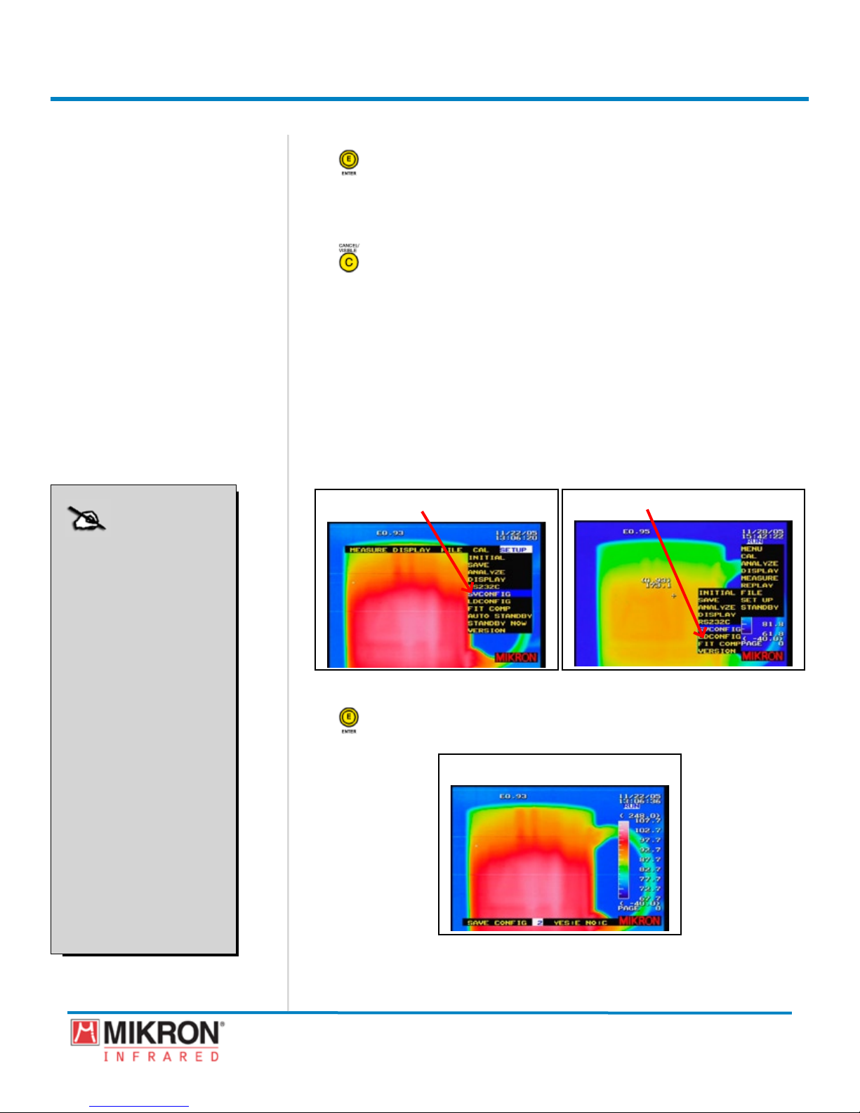
Section 3
4) Press the JOYSTICK [E] button to save the setting and to return to
the main display.
OR
Press the CANCEL/VISIBLE [C] button to cancel out of the auto
standby mode and to return to the main display.
3.10 Working with Configuration Files
The MikroScan 7600PRO provides a number of setup options and
allows you to establish, save, and recall up to 10 customized camera
congurations based selections you made in the Initial Setup menu,
the Save Setup menu, the Analyze setup menu, and the Display
Setup menu.
3.10.1 Savingacongurationle
1) Go to [MENU] → [SETUP] → [SVCONFIG].
Getting Started
NOTE:
If the configuration file
number has already been
assigned to another configuration, a message bar
will appear at the bottom
of the display asking if
you want to over write
the previous configuration
file.
You can either press the
JOYSTICK [E] button to
over write the existing
file,
OR
You can press the CAN-
CEL/VISIBLE [C]
to cancel the request and
select another configuration file number.
button
[SVCONFIG HIGHLIGHTED]
Standard View Menu
[SVCONFIG HIGHLIGHTED]
Classic View Menu
2) Press the JOYSTICK [E] button to gain access to the SAVE
CONFIGURATION Mode.
[SAVE CONFIGURATION SCREEN]
88
MikroScan 7600PRO
Operator’s Manual
Catalog 11180-94
V15.4F 050406

Section 3
Getting Started
3) Toggle the JOYSTICKupordowntoselectacongurationle
number from 1 to 10.
[SAVE CONFIG FILE NUMBER]
If the conguration le number has already been assigned to
another conguration, a message bar will appear at the bottom
of the display asking if you want to over write the previous
conguration le.
You can either press the JOYSTICK [E] button
to over write the existing le,
OR
4) Press the JOYSTICK [E] button to save the setting and to return to
the main display.
OR
Press the CANCEL/VISIBLE [C] button to cancel out of the auto
standby mode and to return to the main display.
You can press the CANCEL/VISIBLE [C]
button to cancel the request and select another
conguration le number.
89
MikroScan 7600PRO
Operator’s Manual
Catalog 11180-94
V15.4F 050406

Section 3
Getting Started
3.10.2 Loadingasavedcongurationle
1) Go to [MENU] → [SETUP] → [LDCONFIG].
[LDCONFIG HIGHLIGHTED]
Standard View Menu
[LDCONFIG HIGHLIGHTED]
Classic View Menu
2) Press the JOYSTICK [E] button to gain access to the LOAD CONFIGU-
RATION Mode.
[LOAD CONFIGURATION SCREEN]
3) Toggle the JOYSTICKupordowntoselectacongurationle
number from 1 to 10.
4) Press the JOYSTICK [E] button to save the setting and to return to
the main display.
OR
Press the CANCEL/VISIBLE [C] button to cancel out of the auto
standby mode and to return to the main display.
90
[LOAD CONFIG FILE NUMBER]
MikroScan 7600PRO
Operator’s Manual
Catalog 11180-94
V15.4F 050406
 Loading...