

Page 1
w
w
w.
md
e
t
e
c
tor
s
.c
o
mw
w
w.
md
e
t
e
c
tor
s
.c
o
m
PULSE INDUCTION METAL DETECTOR
STINGER
USER’S GUIDE
MADE BY MIKRON
BULGARIA
2006
Page 2

w
w
w.
md
e
t
e
c
tor
s
.c
o
mw
w
w.
md
e
t
e
c
tor
s
.c
o
m
2
a "STINGER" is an impulse metal detector with an LCD – Display, digital and graphical
presentation of the level of signal and parameters of discrimination and working modes, as
well as of the state of temperature of the storage battery;
a Fully automatic balance to ground conditions with memorizing and adapting to the
level and parameters of the background of soil and their elimination by the general
signal.
a Reporting of the influence of earth magnetic field and its isolation from the general signal
a Reporting of side disturbances and their full elimination during work
a Possibility for work in premises and in proximity to electric networks – full suppression of
50 Нz disturbances.
a 10 regimes of work - 5 dynamic and 5 static - for correct localization of the object.
a General mode of work for all metals.
a Three modes of discrimination - 1 for normal soil, 1 for soil with high mineralization, and 1
for high mineralized soils with changing background within wide ranges + outer disturbances.
a Choice of 2 types of sound indication - VCO (multi – frequency one) or two-tonal
indication, low tone for magnetic and high tone for non – magnetic (non - ferrous metals).
a Built – in storage battery, providing 10-20 hours of constant work depending on chosen
power
a Regulation of the power of emitted impulses
a Automatic charge of the battery – measuring of charged capacity and tracking of
temperature during charging;
a Tracking of the capacity of the storage battery and automatic signal and turning off at
achieving of a critical minimum.
a Possibility for setting of over 30 working and service parameters providing comfortable
and effective work under various conditions of work.
a Possibility for quick and easy access to all settings in the menu;
a All these possibilities allow „STINGER“ to work perfectly under any ground conditions,
including at high mineralized and polluted sites!
„STINGER“ has the following parts for control:
Switcher "ON – OFF" for turning on and turning off
Buttons "SELECT", "◄ and ►" serve for work with the menu and the settings, selecting of
a mode of discrimination and motion.
Button "CLEAR GND" – serves for automatic setting of the device to ground conditions
of terrain where it works.
Button "MODE" — used at the modes of discrimination and serves for momentary switching
into „ALL METALS" mode for precise localization of object without losing of the value of
memorized balance to the ground in the discrimination modes, as well as for balancing to
Page 3
w
w
w.
md
e
t
e
c
tor
s
.c
o
mw
w
w.
md
e
t
e
c
tor
s
.c
o
m
3
the conditions of the soil through pressing and holding of the "MODE" and momentary
pressing of "CLEAR GND"
- Button "DISCR" – serves for turning on and off of the discrimination modes.
1. Setting and way of work:
Seeking frame is assembled and is placed on the ground paying attention to the range and
there don't have to be any metal objects.
The cable is sub - connected to the device. The device is turned on by "ON – OFF" and
you see „Start Detector“ on the display. Nullification starts and balancing to ground
conditions during which time the display shows "CLEAR" and you can hear a single
sound. This lasts for 3 – 4 sec., then it is followed by a double short sound and the
device is turned on in general mode of "ALL METALS". If you wish to work in a mode of discrimination
"DISCR", the you have to push the button "DISCR", at which the device is switched into
discrimination mode and the display shows "DISCR.1". Its next pushing switches again the
device into "ALL METALS" mode.
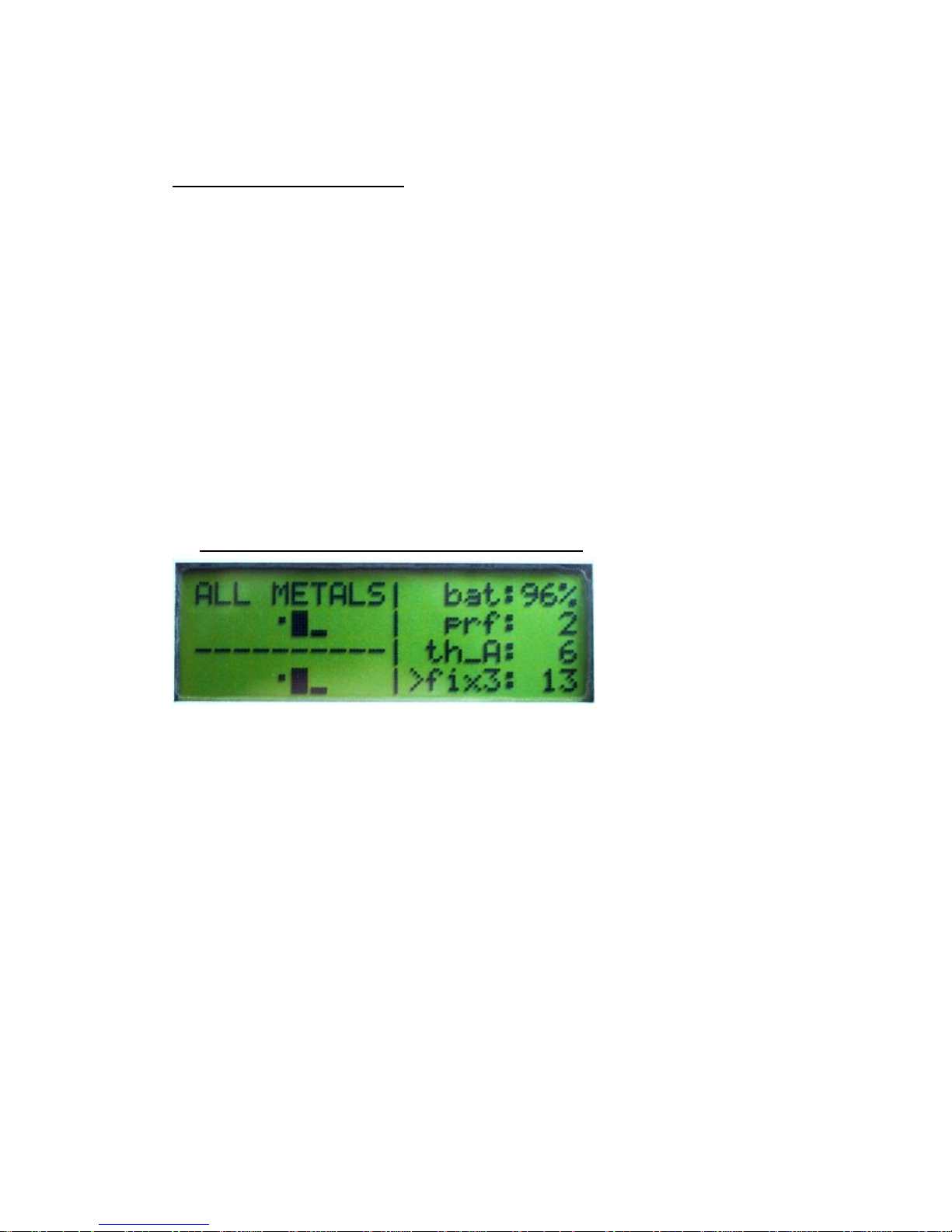
2. Working with the device in "ALL METALS" mode
In this mode the display shows "ALL METALS". Constantly shown aer the level of signal
in graphical and digital look, the capacity of the storage battery, chosen power, the level
of co – working of the sound and the working mode, as follows:
- 1st row to the right – capacity of the battery in percent: 0%-100%
- 2nd row to the right – chosen profile of work - "prf1" or "prf2". At both profiles the device
works with different impulse power - "prf1" – reduced, or "prf2" – full power.
- 3rd row to the right – threshold of sound, level after passing of which a sound appears
- 4th row to the right – the level of signal from the registered metal in figures – from 0 –
400. If there is signal of metal within the range of the coil, disturbances or influence by
soil, upon pressing of "CLEAR GND" indication will become "0". After removal of the
source of the signal from the coil range, indication will become of negative value. In order
to be nullified, you have to push again "CLEAR GND". Upon pushing and holding of
"CLEAR GND" for more than 4 sec the devices is restarted.
The device can work in 10 modes of speed of seeking – 5 static (for precise
localization of object) - "FIX0"- "FIX4", and 5 dynamic (for seeking with motion) – "MOV0"
– "MOV4".
Page 4
w
w
w.
md
e
t
e
c
tor
s
.c
o
mw
w
w.
md
e
t
e
c
tor
s
.c
o
m
4
"FIX“ are static modes of seeking, i. e., the device constantly reacts to a metal
located within the range of the coil. They are suitable for localization of the exact place of
an already fixed metal, and one may constantly work in this mode. Fastest one is the
"FIX0" mode, and slowest one is "FIX4".
"MOV" are dynamic modes of work with a various speed of seeking. The
difference among these modes is in the time for automatic nullification of appeared
signals, i. e. the device is constantly set additionally, but with a various speed at
individual modes. Fastest one is the "MOV0" mode, and "MOV4" is slowest among the
dynamic modes. At these modes the device reacts to metal objects within the range of
the antenna only at motion of the antenna above them.
On the 2nd and 4th row of the display to the left graphical indicators are depicted of
the level for more comfortable tracking of the changes in the signal. Indicators can show
positive or negative levels respectively increasing to the right or to the left from the
dividing zero point of each of them.
The indicator on the 2nd row is indicator of the momentary signal. At a "FIX" mode
it repeats the indicator of the general signal. In "MOV" mode it only shows the change in
the signal.
The indicator on the 4th row is an indicator of the general signal. It shows the
summary signal of the coil without processing.
Normally, both indicators show positive values at a presence of a signal, after its
disappearance they show "0" or hesitate (-1...0...+1).
Should within the coil range there falls in a metal object, it provokes a signal which
is depicted on the 2nd level of the indicator and of the digital indication of the signal.
Should this signal is louder than the chosen threshold of the sound "tr_A", a sound is
heard with a frequency which depends on the level of the signal. The more louder the
signal, the more higher the sound frequency.
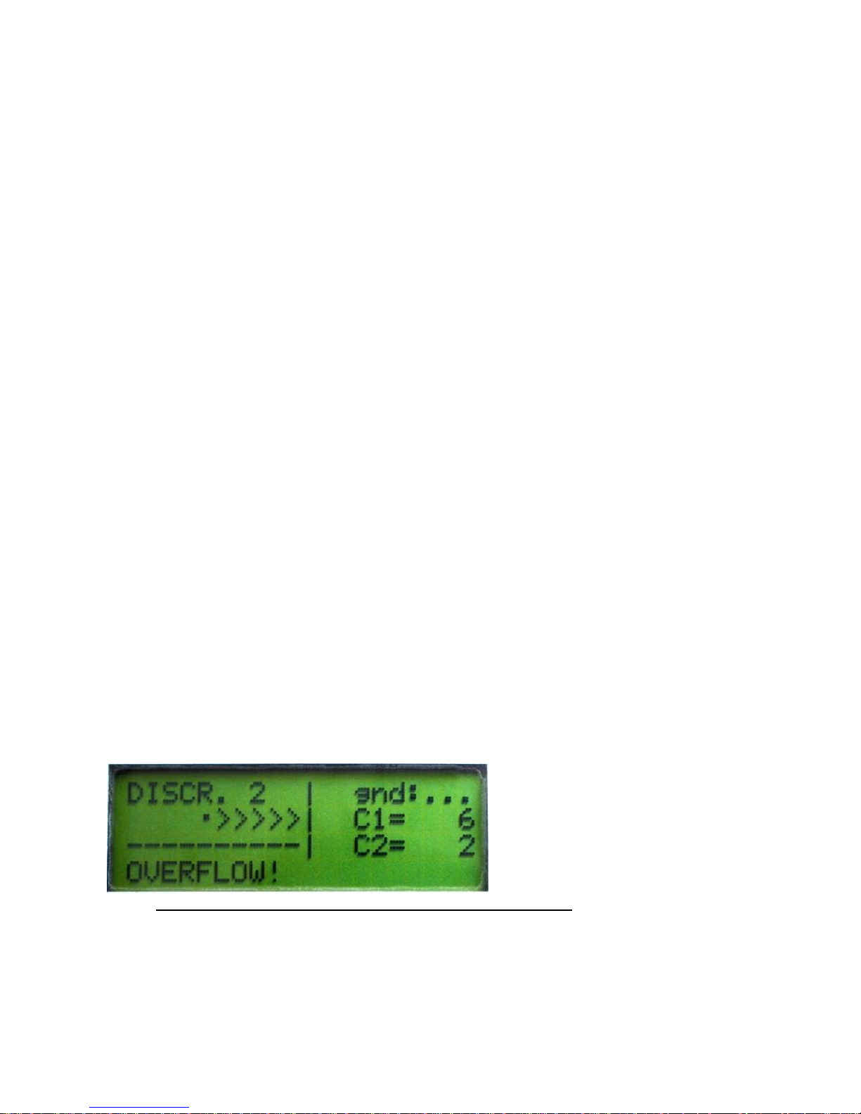
Should the general signal becomes higher than "90", level indicators show
">>>>>>>>", and the digital indication continues to track the increase, the sound is also
changed. If the level of overfill is achieved, he sound is changed to a very loud signal
tone, and „OVERFLOW“ appears on the 4th row of the display.
3. Setting of working parameters in "ALL METALS" mode:
setting of the threshold of co – working of the sound "tr_A" – this is the level of signal
after passing of which a sound is heard. The device may be set at such strength of signal
to react with sound. This is done with change in the parameter "tr_A". For this purpose
the arrow is moved through "SELECT" to be against „tr_A" and through the buttons "◄
Page 5

w
w
w.
md
e
t
e
c
tor
s
.c
o
mw
w
w.
md
e
t
e
c
tor
s
.c
o
m
5
and ►" desired value can be chosen. For end you press "SELECT" and the arrow goes
down again on the 4th row for choice of "FIX" or "MOV" modes. The value of "tr_A" may
be changed only at "FIX" mode, in modes "MOV", pressing of „SELECT“ is not serviced
by the software. The lower the value of „tr_A", the greater the sensitivity of the device.
For instance, if at a balanced device the constant signal from soil is "1" and we have
chosen for "tr_A" a value of "1", then a sound signal is going to appear when the general
signal becomes greater than "1". If for example for "tr_A" a value of "6" has been chosen,
then the device is going to react with sound at a considerably stronger signal – value
greater than "6". Greater values of "tr_A" can be selected if the general signal from the
background of soil changes within wider limits, in order the device to be calm, aiming a
sound signal not to ne produced which is not due to detected metal, but the greater the
value of “tr_A”, the more sensitivity of the device decreases!
- change of working power - the device can work in a mode of full power "prf2“ and
reduced power "prf1" of emitted signal.
Selection of the one or of the other profile is done through pressing of "SELECT"
until the arrow is fixed on the 2nd row to the right before "prf" and through the "◄ and ►"
buttons the desired power is chosen "prf1" or "prf2". Work is normal in "prf2" in order a
normal depth to be achieved, and "prf1" is usually used when a large object is detected
at a small depth in earth. Then the signal is continuous in order to determine the exact
place of the object it is more convenient to use „prf1“.
Thus the signal from the detected object becomes much shorter. It is necessary to
have it in mind that at every switching of “prf1” or “prf2” the device restarts, in order to
define all working parameters in accordance with the power chosen.
In case of disbalance you should push “GND CLEAR” and the antenna should at
the same time be close to the ground.
When working at “ALL METALS” it is possible to some extent to determine the
size of the detected object, by pressing the button “MODE”. Than the device works at
“CHECK” mode, which is used for quick checking the length of the signal. Non-ferrous
metals and the very small ferrous ones a registred with a short signal, while the big
ferrous (magnetic) and and the big non-ferrous metals – with a long signal. The depth at
which the object is berried is also important.
4.Setting up the working parameters in “DISCR” mode
“STINGER” has 3 discrimination modes - “DISCR.1”, “DISCR.2” and “DISCR.3”,
that are chosen by pushing the “SELECT” button, until the arrow points the discrimination
indication - 1st line and the “DISCR” mode should be on.
Page 6

w
w
w.
md
e
t
e
c
tor
s
.c
o
mw
w
w.
md
e
t
e
c
tor
s
.c
o
m
6
When discrimination is on, besides the signal strength two more values light up C1
and C2, which when a ferrous (magnetic) metal is registered have negative values , and
in case of a non-ferrous (non-magnetic) metal – have positive values. “C1” is the value
for chromaticity of metal, and “C2” - is a value for its magnetism.
Most often when a non-ferrous metal is detected C1 has a very big value, e.g. +10
+15, while the value of C2 is around zero.
When foil, aluminium and iron that is not rusty, C1 and C2 have negative values,
and their values are big and positive, when the non-ferrous metal is pure, without alloys –
gold, bronze, copper, silver. When a highly rusted iron is detected, C2 has a high
negative value, e.g. -10 -15, and C1 is around zero.
C1 and C2 can have different values if ferrous and non-ferrous metal is present within the
coil range.
The values C1 and C2 appear only when metal is detected, and when the signal is
missing , “tr_C” and “tr_D” light up in their place, as:
“tr_C” is the threshold of sound change from low to high tone. It expresses the
value of C1, before which the signal is a low tone and after it - a high tone. For example
if “tr_C” is 5 , signals with levels lower than 5 will be registred with a low tone, and in
case of signals exceeding 5, a high tone will be heard. Usually “tr_C” should be 1 so that
signals with positive “C1” are registred with a high tone, or non-ferrous.
“tr_D” is the threshold of sound harmonisation in discrimination mode. It
determines the minimum rate of signal, after which the calculation of the C1 and C2
values begins. The “tr_D” setting lights up on the 3d line at the right side and is
analogical to “tr_A”. Smaller values of “tr_D” will ensure the beginning of the
discrimination in case of weaker signals, but that could lead to more unstable indications
or fake signals.
Page 7

w
w
w.
md
e
t
e
c
tor
s
.c
o
mw
w
w.
md
e
t
e
c
tor
s
.c
o
m
7
The balance indicator “I - I” regarding the soil background lights up on the 1st line
at the right side and shows if the device is balanced when the signal is missing. When
the device is balanced and there are no metal objects within the reach of the antenna,
the indicator should have two equal levels to the right and to the left of the “ - ” symbol. If
there is a difference between the two levels the device should be balanced again, by
pressing the “CLEAR GND” button. The level of the two columns of the balance indicator
shows also the power of the signal from the soil. The higher the level, the stronger the
signal and thus the operator can get orientated which discrimination mode to use – when
the signal is weak (low indicator level) it is recommended to work at “DISCR.1”, whet it is
at average level - “DISCR.2”, and at high levels (strong signal from the soil) - “DISCR.3”
When the “SELECT” button is pushed at a discrimination mode and movement of
the arrow (>) at 1st line, the type of discrimination can be chosen “DISCR.1”, “DISCR.2”
or “DISCR.3”. If the discrimination type is not changed, after a second pushing of of the
“SELECT” button, the arrow (>) will position itself at the 3d line and “ggt2” and “ggt3” will
light up. By them the possible range of signals is chosen when it is balanced to the soil
conditions. “ggt2” - at “DISCR.2”, and “ggt3 ” at “DISCR.3”.
“DISCR.1” is an appropriate mode when the soil background is disparagingly small
and does not significantly change the signal, received when a metal object is detected.
-When the sall is more mineralised, it transmits a signal, that can increase significantly,
especially when the frame is close to the ground surface. The highly mineralised soils,
especially if they have a high moisture content, additionally increase the total signal and it
can have high values. If there is a non-ferrous metal in this type of soil, it will invert the
overall signal to more positive values, thus the sensitivity will decrease because of the
soil background.
-For cases like that the “DISCR.2” mode is appropriate, where the average background
levels are assumed to be equal to zero and each instant increase of the signal detected
from a metal object will be signalised.
The sensitivity at this mode is greater, because the signal appears before the soil
background is totally compensated. For example if the soil background is “C1= - 7”, in
case of increasing to - 6 , - 5 the device will make a signal, while at a normal
discrimination, the signal should increase over 0, in order for a sound signal to appear.
Somewhat a flaw of this mode is, that it can give a signal when even when a
ferrous metal is detected, with its own coefficient, more positive than that of soil. For
example if the signal from the soil is - 7, and that of metal is - 3, the device will make a
Page 8

w
w
w.
md
e
t
e
c
tor
s
.c
o
mw
w
w.
md
e
t
e
c
tor
s
.c
o
m
8
sound signal. In this case, the values of C1 and C2 should be observed, and thus the
operator can make a conclusion regarding the type of the metal.
-In the “DISCR.3” mode the signal is analysed and in case of change, it is calculated
what part of it is a result of the overal soil background and to what extend it is a result of
the impact of another object. Thus it is calculated what is the signal coming from the
object itself, it is close to this, if the soil does not have its own background or if the object
is in the air. For example if we have a signal from a metal object with its own coefficient
“C1= - 3” located in soil, that has its own background “- 7”, at this mode there will be no
signal, because after obtaining the signal of the metal from the soil background and its
discrimination, the result will be negative (“C1= - 3”). Similar to the “DISCR.1” there will
be a signal only when the values are positive. The difference between “DISCR.3” and
“DISCR.1” is that with “DISCR.3” the signal from the object does not have to compensate
the soil background fully in order to react with sound. From the overal signal the soil
background signal separates and only the useful signal stays. If discriminated nonferrous metal, the device will react with sound although the soil background could have
high negative value. The sensitivity with “DISCR.3” is higher than with “DISCR.1” but it is
better to use “DISCR.3” on soils with increased mineralization and a background
changing within large limits and also upon presence of outer disturbances.
One should bare in mind that the efficiency of the discrimination depends quite on
the size of the metal object and the depth it is situated in the soil. It could be 100%
accurate for small and middle-sized objects situated on the surface layer (with depth
approximately 50-100 cm in the soil), up to 50-60% accurate for big metal utensil (1x1m
for instance) buried at 2-3 m in the soil. That is to say the bigger the object the deeper it
is buried in the soil and the harder it is to be discriminated. Smaller coils have better
opportunities for discrimination.
5. Balancing towards the soil background in discrimination modes.
In “DISCR.2” and “DISCR.3” an opportunity is provided to set the device
automatically according to the soil background.
When pressing the “SELECT” button in discrimination mode and moving the arrow
(<) on first row you can select the discrimination mode “DISCR.1”, “DISCR.2”, or
“DISCR.3”. If the discrimination type does not change with the next pressing of the
“SELECT” button the arrow will be positioned on third row and “ggt2” and “ggt3” will be
displayed. Through them the acceptable variations could be chosen when balancing to
the soil conditions. “ggt2” - at “DISCR.2” and “ggt3” at “DISCR.3”.
Page 9

w
w
w.
md
e
t
e
c
tor
s
.c
o
mw
w
w.
md
e
t
e
c
tor
s
.c
o
m
9
For adaption to the soil press and hold the “CLEAR GND” button. On the first row
of the display you will see “Get ground” and the device will make a continued sound for
adaptation start. After that you must bring closer and then move away the search coil to
and from the ground surface within the range of normal searching distances, 5-20 cm for
instance. With every move up-down the devices analyses the receiving signal and makes
short sound.
If the parameters of the soil background exceed the range of the current chosen
background, adaptation shall be restarted and the device will make that long sound
again.
When in full movement up-down the short sound stops for additional setting or
long one for adaptation restart despite there might be signal alterations because of that
particular movement then the adaptation is completed meaning the device has
rememered the variation limits of the soil signal. Then you release the “CLEAR GND”
button and you will hear a confirmative double short sound for successful balancing of
the soil background. After the successful balancing on the first row, on the right side of
the display you will see the accepted by the appliance average value for soil background,
“gnd 17” for instance. This value is considered to be the conditional environment (“0”) of
discrimination. The value of “C1” becomes “0” and every signal with more positive value
will be signalized with sound.
If you release the “CLEAR GND” button before the successful balance of the device you
will see “gnd ???” - signalization for missing tone and it will constantly release short
sounds.
If the soil signal varies in wide limits a constant restarting of the soil balance is
possible. In that case you should increase the acceptable tolerance of adaptation as you
increase the parameter “tr_D” of 2 or 3 (1 is normal). That will allow adaptation at bigger
variations but it will result in certain decrease in the sensitivity to non-ferrous metals.
If after successful balancing during search the signal from the soil background
fades away sufficiently and gets even quieter than the remembered minimum a
signalization for missing background will appear - “gnd ???” In that case you should
either bring the aerial closer to the soil during search or repeat the balancing.
When locating a metal object in the soil during search in discrimination modes the
device makes a short sound with one frequency. That makes it harder to find the exact
location of the object in the soil than it is with a sound with changing frequency. For the
purpose an opportunity is provided for transitory changing into “ALL METALS” mode for
locating during discrimination search. This is done by pressing and holding the “MODE”
button and on the display you will see “ALL METALS” and the device switches to a mode
of multi-frequency sound indication for the easier locating of the object. After releasing
the “MODE” button the device returns to the discrimination mode and the balance
settings he had before. If you switch off “DISCR” and go to “ALL METALS” mode the
object could be located as well but after that when you switch on to “DISCR” again you
Page 10

w
w
w.
md
e
t
e
c
tor
s
.c
o
mw
w
w.
md
e
t
e
c
tor
s
.c
o
m
10
will have to perform soil background balancing again whereas if you press and hold the
“MODE” button for locating the device keeps the settings it had before the discrimination
mode.
The discrimination mode “MODE” could also be used for balancing the device to
the soil conditions by pressing and holding “MODE” and transitory pressing “CLEAR
GND”. Normally when working in discrimination mode the pressing of “CLEAR GND” is
not maintained by the software.
6. The detection depth depends on the following:
-size, shape and location of the object in the soil. The bigger the reflecting surface of the
object the deeper it is to be found;
-soil composition and mineralization level – the drier and more homogeneous the soil the
easier it will be to adapt the device and for the device to detect deeper. Under stones, dry
sand or in clay utensil, metals are easier to be found than in freshly dug out or damp soil.
-the longer the object has been in the soil the easier it will be to be found as a result of
the good contact with the soil. The longer the object has been in the ground the bigger
the field is and imitates bigger object!
-type of detecting coil. The bigger the diameter of the coill the deeper it will be able to
detect metals.
-operator's experience and skills.
You can do field tests by yourself using the device if you bury different metal objects in
different depth but you should leave them in the ground for at least 3 months. Thus the
test results will be more reliable. You should mind the soil type and the moisture
composition in it. Best results are received when the soil is dry.
7.Charging storage batteries and indications for their status.
“STINGER” has a built-in storage package 18V/2,3Ah, which is able to provide 10-
20 hours of working process without any interruption depending on the chosen power
and the type of the used search coil. Bigger coils consume more power and thus the
working time is shorter.
The accumulators' status is shown on the first row on the right as per cents of the
capacity (0%-100%). When the capacity decreases below 0% it will show “---” and if fully
charged batteries or if using external supplying block with higher voltage it will show
“+++”. If it shows “---” on the forth row of the display it will say “SIGNAL ERROR”.
The charging is automatic and begins when the device is SWITCHED OFF and
you plug the charger into the charging jack of the back panel of the device. The jack cage
is “-” and the middle terminal is “+”. During charging on the display you will see transitory
and maximum voltage of storage batteries, their temperature, as well as the charged so
far capacity and on the lower row of the display “Charging”.
Page 11

w
w
w.
md
e
t
e
c
tor
s
.c
o
mw
w
w.
md
e
t
e
c
tor
s
.c
o
m
11
The charging continues till the moment when the batteries reach their maximum
capacity which also reflects in increase in the temperature. When reaching their full
capacity and increase in the temperature up to 40ºC the charging stops and down on the
display you will see “FULL”. At the same time the device will start to make short sound
signals.
Always charge device's storage batteries ONLY with the paired chargers to it. Thus
you will prevent damages or confusion between “+” and “-” because the use of
other chargers or adaptors may lead to irretrievable damages in the batteries!
Possible problems during exploitation of “STINGER”:
1.When switching it on you can not hear a sound, there is no information on the
display, no indication that the device is switched on. It might indicate for:
-storage batteries are dead (usually after a long period of time). Charge the batteries with
the charger. If the problem is not solved contact the service-station (office) of the
company manufacturer or the local distributor.
-the accumulator block consists of three elements 6V/2,3V connected in series. If just
one of them is damaged the connection between them will be destroyed and practically
the device will be left without power supply.
2.The working depth is significantly shallower than the normal. It might indicate
for:
-storage batteries could be dead – pay attention to the shown % for the capacity of the
storage batteries. If it is “---” charge the batteries with the automatic charger. If you can
not solve the problem contact the service-station (office) of the company manufacturer or
the local distributor.
3.During detection the device does not work stable, makes strange sounds which
are not due to a metal detection. It might indicate for:
-irregular electromagnetic external interruptions.
-problems with the aerial cable – disconnected conductor, a shot circuit or bad
connection in the coupling. If disconnected conductor or shot circuit in the cable on the
lower row of the display you will see “SIGNAL ERROR”.
It is possible after continuance work and many times of switching on and off the
cable's coupling to the jack box the contact between them to be destroyed. There are 2
terminals with sightholes in the jack of the back panel of the device. Put something sharp
like a knife or a screwdriver in the sightholes and make them wider. Thus the coupling
will fit better into the jack which will improve the contact between them. It is possible in
Page 12

w
w
w.
md
e
t
e
c
tor
s
.c
o
mw
w
w.
md
e
t
e
c
tor
s
.c
o
m
12
the presence of some kind of dirty like dust or moisture to clean the terminals with cottonwool and alcohol. If you can not solve the problem contact the service-station (office) of
the company manufacturer or the local distributor.
4.The device works only with headset and when working with amplifier you can not
hear a sound. Usually that happens when the headset jack is damaged. In that case
contact the service-station (office) of the company manufacturer or the local distributor to
change the jack.
5.When switching on the charger to charge the storage batteries you will see on
the display “FULL”. Usually that happens when the device was kept in the cold and the
battery temperature is around or below 0ºC. If the microprocessor can not define the
batteries temperature you can not strat the charging and on the display you will see
“FULL”. Leave the device in a warm premise and wait till the temperature of the batteries
increases up to 5- 6ºC.
If you can not solve the problem contact the service-station (office) of the company
manufacturer or the local distributor and do not charge with any other devices or
ordinary adaptors.
6.Batteries charge quickly and after that during the working process they go dead
quickly. Usually that happens when the batteries are really old and need replacement.
Contact the service-station (office) of the company manufacturer or the local distributor
for change of the storage batteries.
The Manufacturer (trader) does not bear any responsibility if you use the device in
violation of the law, on archeological or forbidden for search places as well as on private
property without the knowledge or the permission of the owner.
Protect the environment and always fill back in the holes you have dugged out!
 Loading...