


YOUR PARTNER
FOR PROFESSIONAL
HD SOLUTIONS
0LNUR0
User
Manual
MVD600
H.264/AAC Source Decoder

ii
Trademarks
©2005 MikroM GmbH. All rights reserved. All other trademarks are the property of
their respective owners.
Statement of Conditions
In the interest of improving internal design, operational function, and/or reliability,
MikroM reserves the right to make changes to the product(s) described in this document without notice.
MikroM does not assume any liability that may occur due to the use or application
of the product(s) or circuit layout(s) described herein.
Customer Support
For assistance with installing and configuring your MikroM system or with questions
or problems following installation:
• Check the MikroM Web page at http//www.MikroM.com.
• Call Technical Support at the phone number listed on the Support Information Card that shipped with your product.
• Email Technical Support at support@MikroM.com.
Defective or damaged merchandise can be returned to your point-of-purchase representative.
Internet/World Wide Web
MikroM maintains a World Wide Web home page that you can access at the universal resource locator (URL) http//www.MikroM.com. A direct connection to the Internet and a Web browser such as Internet Explorer or Netscape are required.
Acknowledgement
The MVD600 has been developed by MikroM based on the solid know-how and Intellectual Property (IP) in H.264/MPEG-4 AVC technology from Fraunhofer/HHI in
Berlin.

CONFIDENTIAL Table Of Contents
MVD600 User Manual 1.0 iii
CONTENTS
Introduction 1 - 1
Feature 1 - 1
Block Diagram 1 - 2
Front Panel 1 - 3
Rear Panel 1 - 3
Functional Description 2 - 1
ASI Receiver 2 - 1
TS Demux 2 - 1
Program Detection 2 - 2
User I/F & Menu 2 - 2
Alarm Control 2 - 3
Video Decode 2 - 3
Audio Decode 2 - 4
Up-Scaling 2 - 4
Frame Store 2 - 4
AES3 Formatter 2 - 5
Audio Embed 2 - 5
Menu Structure 3 - 1
Overview 3 - 1
Programs 3 - 2
Setup 3 - 3
Setup 3 - 4
Status 3 - 4
Technical Specifications A - 1
Interface Specification B - 1

Table Of Contents CONFIDENTIAL
iv MVD600 User Manual 1.0
SD-SDI 1, SD-SDI 2 B - 1
Control B - 1
AES/EBU B - 2
100TX B - 3
Alarm B - 3
ASI-IN B - 4
ASI-THRU B - 4
Firmware 1.0.24 C - 1
Release Note 1.0.24 C - 1
Bug Detection C - 1
Bug Search C - 1
Video decoder stops in some situations C - 1
Added anti-freeze C - 2
Verification C - 2
Conclusion C - 2

CONFIDENTIAL List Of Figures
MVD600 User Manual 1.0 v
FIGURES
Figure 1-1. Block Diagram 1 - 2
Figure 1-2. Front Panel 1 - 3
Figure 1-3. Rear Panel 1 - 3
Figure B-1. Interfaces on Rear Panel B - 1
Figure B-2. Alarm relay principle B - 4

List Of Tables CONFIDENTIAL
vi MVD600 User Manual 1.0
TABLES
Table 3-1. Menu Overview 3 - 1
Table B-1. Control Connector Pin Assignment B - 2
Table B-2. AES/EBU Connector Pin Assignment B - 2
Table B-3. Alarm Connector Pin Assignment B - 3

CONFIDENTIAL Introduction
MVD600 User Manual 1.0 1-1
CHAPTER 1: INTRODUCTION
The MVD600 is an integrated H.264/AAC Decoder, targeting low-resolution TV-like
broadcast services for mobile receivers via terrestrial transmission.
It receives compressed H.264/AAC data being encapsulated in a MPEG-2 Transport
Stream from a ASI interface. A demultiplexer, together with an automatic program
detection & selection mechanism extracts audio/video data from the bit stream to
the audio/video decoder.
The decoder architecture, consisting of a single video decoder and a dual audio decoder allow to decode video simultaneously to two independent audio tracks, to
meet the specific audio requirements (ARIB) in the Japanese market.
Decoded video is formatted for output onto SDI interface. Audio is formatted and
embedded into SDI as well as output directly onto AES interface.
Main building blocks within the MVD600 are an embedded processor module (XScale) and a FPGA with own external memory system, operating as a co-processor.
A real-time Operating System (eCos) allows to perform demultiplexing, audio and
video decoding under real-time constraints in software. Decoded audio and video
frames are stored in FPGA’s memory for formatting, scaling and output, which is
performed by the FPGA.
The firmware of the MVD600 can be updated in the field by software via the Ethernet port. An operator can control the MVD600 from the front panel or via the RS232
control port from a PC with a terminal program.
Packaged into a stainless steel housing with excellent EMC properties, using a robust AC/DC converter and forced internal air-flow finally turn the MVD600 into a
reliable solution for broadcast applications.
Feature
The MVD600 has the following key features:
• MPEG-2 Transport Stream Demux (ISO/IEC 13818-1), supporting ISDBT
• H.264/MPEG-4 AVC Baseline Profile @ Level 1.2 video decoder (ISO/IEC
14496-10 AVC), 384 kbps
• QVGA resolution 320x240 Pixel, 15 fps
• Dual MPEG-2 AAC audio decoder (ISO/IEC 13818-7)
Introduction CONFIDENTIAL
1-2 MVD600 User Manual 1.0
• Low Complexity (LC) Profile + Side-band Replication (SBR)
• Video Up-Scaling & Frame-rate adaptation for SDI output
• 2x Digital video output (SD-SDI) with embedded audio
• 2x Digital audio output (AES3-ID)
• Ethernet port 10/100BaseT, RS232 Control
• Software update via Ethernet
• Alarm relay
• Upgradeable and customizable hardware architecture
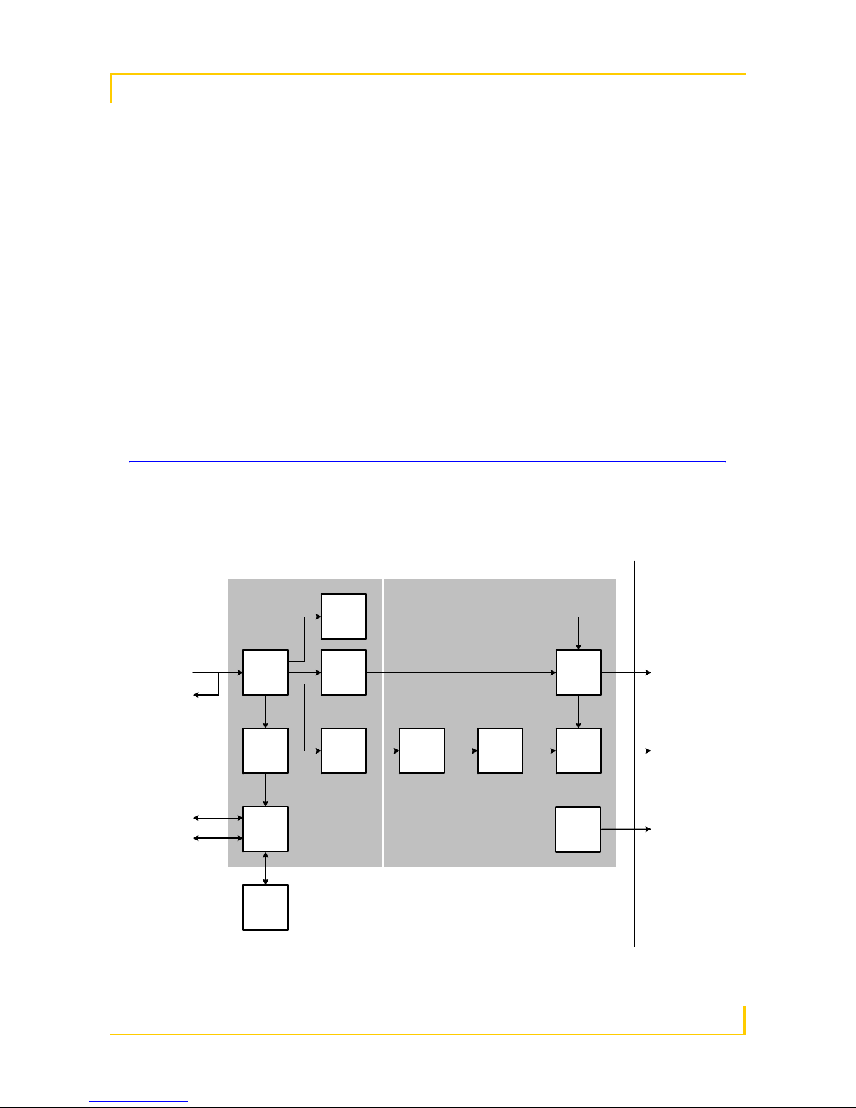
Block Diagram
Figure 1-1 shows the block diagram of the MVD600.
Figure 1-1. Block Diagram
MVD600
FPGA + DRAMµP-Module
Video
Decode
Audio
Decode
Audio
Decode
TS
Demux
AES3
Formatter
Audio
Embed
ASI-IN 2x AES3-id
2x SD-SDI
MVD600_BlockDiagram.vsd
Up-
scaling
Frame
Store
ASI-THRU
Program
Detection
User I/F
Menu
Control
100TX
Alarm
LCD
Jog Dial
Alarm
Control

CONFIDENTIAL Introduction
MVD600 User Manual 1.0 1-3
Front Panel
Figure 1-2 shows the front panel of the MVD600.
Figure 1-2. Front Panel
Rear Panel
Figure 1-3 shows the rear panel of the MVD600.
Figure 1-3. Rear Panel
00
48

Introduction CONFIDENTIAL
1-4 MVD600 User Manual 1.0

CONFIDENTIAL Functional Description
MVD600 User Manual 1.0 2-1
CHAPTER 2: FUNCTIONAL DESCRIPTION
This section describes the main building blocks of the MVD600 and their functionality.
Refer to Figure 1-1 to identifying these building blocks within the entire data and
process flow.
ASI Receiver
• Performing DVB-ASI signal receiption and serial-to-parallel conversion,
including ..
• ASI carrier detection
• ASI signal reception
• ASI transmission clock recovery
• ASI transmission symbol & symbol violation detection
• Symbol-to-data conversion (10/8 bit)
• ASI-Thru clock refresh
• Providing TS data to TS Demux unit
TS Demux
• Performing Transport Stream demultiplexing, bit stream buffering, timestamp extraction and controlling decoder timing, including ..
• Receiving TS data from ASI Receiver unit
• Valid TS bit stream detection
• TS sync word detection & synchronization
• 188/204 Byte packet size detection
• TS Continuity Counter discontinuity detection
• Providing Service Information (SI) like PAT/PMT to Program Detec-

Functional Description CONFIDENTIAL
2-2 MVD600 User Manual 1.0
tion unit
• Filtering TS using the PIDs provided by Program Detection unit
• Buffering Audio and Video Elementary Streams in a FIFO buffer
• Extracting time-stamp information from the bit stream
• Computing decoder start timings
• Computing audio/video output timings
• Setting system time from TS time
Program Detection
• Performing PAT/PMT evaluation, program detection and mode-depending PID selection, including ..
• Receiving SI data from TS Demux unit
• Evaluating PAT, when version number changes, upon CC error and
periodically
• Evaluating PMT, when version number changes, upon CC error and
periodically
• In Automatic mode: Selecting PIDs from the first H.264 program
found via PAT/PMT
• In Service-ID mode: Selecting PIDs for the selected Service-ID
• In Manual mode: Receive PIDs set manually from the User I/F &
Menu unit
• Forcing re-scanning & re-synchronization upon channel-switching
or error
• Provide selected PIDs to TS Demux unit
User I/F & Menu
• Unit performs loading, editing and storing of configuration data, providing decoder status, bit stream and alarm information, and handling firmware updates, including ..

CONFIDENTIAL Functional Description
MVD600 User Manual 1.0 2-3
• Interfacing to the Front Panel LCD and Jog-dial
• Providing structured menu information to Front Panel LCD
• Providing manual configuration data entry (like mode, aspect ratio,
...)
• Loading and storing configuration data to non-volatile memory
(FLASH)
• Interfacing to the RS232 Control port
• Providing log information to the RS232 Control port in log mode
• Providing remote control via RS232 control port in terminal mode
• Interfacing to the 100TX Ethernet port
• Receiving firmware update data from 100TX Ethernet port
• Performing firmware update in save-operation mode
• Computing & providing health information
Alarm Control
• Computing alarm condition & driving alarm signal
Video Decode
• Performing decoding of video Elementary Stream complying to the applicable standard, including ..
• Receiving NAL packets from TS Demux FIFO
• Decoding video frame-by-frame
• Detecting bit stream errors & performing error resilience
• Outputing decoded frame to Up-Scaling unit
• Time-stamp & PCR-based synchronous output

Functional Description CONFIDENTIAL
2-4 MVD600 User Manual 1.0
Audio Decode
• Performing decoding of audio Elementary Stream complying to the applicable standard, including ..
• Receiving encoded audio frames from TS Demux FIFO
• Decoding audio frame-by-frame
• Detecting bit stream errors & performing error resilience
• Detecting missing audio frame & empty audio frame insertion
• Muting/Unmuting audio when re-synchronizing
• Outputing decoded audio frame to AES Formatter unit
• Time-stamp & PCR-based synchronous output
Up-Scaling
• Performing up-scaling and storing of the decoded video frame, including
..
• Receiving decoded video frames from Video Decode unit
• Computing scale parameters from decoder resolution/aspect ratio
and selected output resolution/aspect ratio
• Parameter controlled up-scaling of the decoded video frame
• Storing up-scaled video frame in frame buffer
Frame Store
• Performing storing of up-scaled video frames, including ..
• Receiving up-scaled video frame from Up-Scaling unit
• Storing several up-scaled video frame in frame buffer (SDRAM)
• Converting decoder frame rate to output frame rate by frame-
repitition
• Outputing up-scaled video frame with output frame rate to Audio

CONFIDENTIAL Functional Description
MVD600 User Manual 1.0 2-5
Embed unit
AES3 Formatter
• Performing audio formatting to AES3-ID format and outputing, including
..
• Receiving decoded audio frame from Audio Decode unit
• Routing decoded audio tracks to dedicated output channels
• Computing AES packet header information
• Formatting audio PCM data into AES3-ID transmission format
• Outputing AES formated data to AES3-ID interface and to Audio
Embed unit
Audio Embed
• Performing video raster generation, embedding of video and audio data
into that video raster and outputing, including ..
• Receiving AES3-ID audio data from AES3 Formatter unit
• Receiving up-scaled video frame from Frame Store unit in output
frame rate
• Performing 420 to 422 conversion
• Generating selected video output raster & timing
• Embedding video frame into active area of the video raster
• Embedding AES3-ID audio data into the blanking interval of the
video raster
• Outputing video raster to video interface

Functional Description CONFIDENTIAL
2-6 MVD600 User Manual 1.0

CONFIDENTIAL Menu Structure
MVD600 User Manual 1.0 3-1
CHAPTER 3: MENU STRUCTURE
This chapter provides information about the menu structure of the MVD600.
Overview
Table 3-1 shows gives an overview of the menu structure.
Table 3-1. Menu Overview
Menu Submenu/s Value Unit
Programs Automatic <Select: H.264 program, max. 6 entrys> -
Service ID <Enter: Service ID> -
PIDs <Enter: Video PID>
<Enter: Audio 1 PID>
<Enter: Audio 2 PID>
<Enter: PCR PID>
-
Setup Aspect Ratio <Select: 4:3 or 16:9> -
Test Pattern <Select: Off, Color Square, White Grid or|
Red Grid>
-
Audio 1 Delay <Enter: Audio 1 Delay> ms
Audio 2 Delay <Enter: Audio 2 Delay> ms
Serial <Select: Terminal or Event Log>
Network DHCP - -
Manual <Enter: MVD600 IP Address>
<Enter: MVD600 Net Mask>
<Enter: Gateway IP Address>
-
Update Server <Enter: IP Address of tftp server> -
Save - -
Load - -
Restore Defaults - -
Service Update TFTP -
System Reset - -

Menu Structure CONFIDENTIAL
3-2 MVD600 User Manual 1.0
Programs
• Automatic: Select H.264 service automatically. First H.264 service to
be found will be selected.
• Service ID: Select H.264 service by Service ID. Manually enter Service
ID.
• PIDs: Select H.264 service by PIDs. Manually enter audio, video and
Status Program Number
Service ID
PCR PID
ES0
ES0 Pid
ES1
ES1 Pid
ES2
ES2 Pid
ES3
ES3 Pid
ES4
ES4 Pid
ES5
ES5 Pid
-
Video Res
Ratio
Frames
Mon Ratio
Pixel
-
fps
-
Audio Delay 1
Delay 2
Ch1/2
Ch3/4
ms
ms
-
-
Health Temp
12V
5V
3.3V
2.5V
1.2V
Fan1
Fan2
°C
V
V
V
V
V
rpm
rpm
Versions Software
PCB
PLD
Table 3-1. Menu Overview
Menu Submenu/s Value Unit

CONFIDENTIAL Menu Structure
MVD600 User Manual 1.0 3-3
PCR PIDs.
Note Default mode is Automatic.
Note Switching mode from Automatic/Service ID to PIDs keeps the PIDs active,
which have been found in Automatic/Service ID mode.
Note PAT/PMT version number changes are recognized automatically in Auto-
matic and Service ID mode.
Note PID values are in hexadecimal notation.
Setup
• Aspect Ratio: Select aspect ratio of display monitor between 4:3 and
16:9.
• Test Pattern: Select between different video test pattern for monitor
calibration (Color Square, White/Red Grid).
• Audio 1 Delay: Enter audio delay value for audio channel# 1/2 (unit is
ms).
• Audio 2 Delay: Enter audio delay for audio channel# 3/4 (unit is ms).
• Serial: Select Control port mode between Terminal and Event Log
mode. See also section “Control” on page 1.
• Network: Configure Network port by selecting mode and entering network addresses.
• DHCP: IP address and net mask of the MVD600 will be set auto-
matically by the DHCP server.
• Manual: Enter IP address and net mask of the MVD600, and IP ad-
dress of the Gateway manually.
• Update Server: Enter IP address of the tftp Update Server. For ac-
tivating update process refer to menu Service > Update below.
• Save: Save current mode and parameter configuration. After power-up
or reset the saved configuration will be loaded automatically.
• Load: Load saved mode and parameter configuration.
• Restore Defaults: Restore default mode and parameter configuration
(factory defaults).

Menu Structure CONFIDENTIAL
3-4 MVD600 User Manual 1.0
Note Aspect ratio is converted automatically depending on the aspect ratio of the
decoded video. Default aspect ratio is 4:3.
Note Single tile of test pattern Color Square measures 256x256 Pixel. Grid of
test pattern White/Red Grid measures 16x16 Pixel, line width is 2 Pixel.
Note Selecting Terminal mode in the Serial menu allows to remote control the
MVD600 from PC using a terminal program (e.g. Hyperterminal). See also
section “Control” on page 1.
Note Selecting Event Log mode in the Serial menu allows to track internal event
logs. This mode is usefull for problem analysis and maintenance.
Note The IP address of the Update Server must be set although the DHCP option
has been choosen!
Setup
• Update: Starts update process by searching for Update Server with
TFTP service, downloading firmware update file and flashing the new
firmware. This process takes few minutes of time. DO NOT UNPLUG
POWER WHILE UPDATE IS IN PROGRESS! This could corrupt the
firmware, which only could be repaired in the factory.
• System Reset: System reset is performed and the saved mode and parameter configuration is retrieved.
Note Several free and non-free TFTP programs are avaliable in the Internet.
Status
• Program: Displays program related information, which has been extracted from the bit stream: Current program number, Service ID and
PCR PID; as well as stream type information and PID value of the first
six Elementary Streams found in the bit stream.
• Video: Displays video related information: Resolution, aspect ratio and
frame rate of the decoded video, and the selected display monitor aspect
ratio.
• Audio: Displays audio related information: Selected delay for both
channels and the audio channel mode (Mono, Stereo, Dual Mono).
• Health: Displays system related information, measured: Temperature
inside the housing, voltages and rotation speed of the fans.

CONFIDENTIAL Menu Structure
MVD600 User Manual 1.0 3-5
• Versions: Display maintenance related information: Software, PCB and
PLD revision numbers. Please have these version numbers at hand when
you contact support hotline.

Menu Structure CONFIDENTIAL
3-6 MVD600 User Manual 1.0

CONFIDENTIAL Technical Specifications
MVD600 User Manual 1.0 A-1
APPENDIX A: TECHNICAL SPECIFICATIONS
This appendix provides technical specifications for the MVD600.
Standards Compatibility
Transport: MPEG-2 Transport Stream (ISO/IEC 13818-1)
Video: H.264/MPEG-4 AVC Baseline Profile @ Level 1.2 video
decoder (ISO/IEC 14496-10 AVC), 384 kbps
Audio: MPEG-2 AAC audio decoder (ISO/IEC 13818-7)
Data Rate
Transport: 108 Mbps max.
Video ES
1
: 384 kbps max.
Audio ES
1
: 2 x 70 kbps typ.
Interfaces
Transport: ASI-IN, ASI-THRU
Video: SD-SDI (2x)
Audio: AES3-ID (2x)
Control: RS232
Network: 10/100BaseT Ethernet
Alarm: General Purpose Output
Power Supply
Voltage: 100-240 VAC, 50/60 Hz
Power Consumption: 15 W
Physical Specifications
1. ES Elementary Stream

Technical Specifications CONFIDENTIAL
A-2 MVD600 User Manual 1.0
Dimensions: 48.4 x 4.45 x 25.3 cm (19 x 1.8 x 10 in), 1 RU
Weight: 3.2 kg (7.05 lbs)
Cooling: Forced air flow, front-to-back
Environmental Specifications
Operating Temperature: 0 to 40° C (32 to 104° F)
Operating Humidity: 90% maximum relative humidity, non-condensing
Storage Temperature: -20 to 70° C (-4 to 158° F)
Storage Humidity: 95% maximum relative humidity, non-condensing
Electromagnetic Compliance
US: FCC - 47 CFR Part 15 Class B
EU: CE - EN 55103-1/-2

CONFIDENTIAL Interface Specification
MVD600 User Manual 1.0 B-1
APPENDIX B: INTERFACE SPECIFICATION
This appendix provides the interface specifications of the MVD600.
Figure B-1 shows the interfaces on the rear panel.
Figure B-1. Interfaces on Rear Panel
SD-SDI 1, SD-SDI 2
Logical: SD digital video output
Purpose: Digital video output in YUV/SD-format with embedded
audio
Format: Video SMPTE259M (D1-SDI)
Audio SMPTE272M
Protocol: Video ITU-R BT.601-5partA, SMPTE259M (D1-SDI)
Audio AES3
Electrical: 800 mV p-p, 75 Ohms
Physical: 1 x BNC receptible
Control
Logical: Bidirectional control port
Purpose: Remote control
Format: VT100
Protocol: RS232C (115,200 Bps, 8 data bit, no parity, 1 stop bit,
no flow-control)
Electrical: EIA-232
Physical: 1 x DSUB9 receptible
48

Interface Specification CONFIDENTIAL
B-2 MVD600 User Manual 1.0
AES/EBU
Logical: Digital audio output
Purpose: Multi-channel digital audio output as AES3
Format: AES3-ID
Protocol: SMPTE276M(AES3)
Electrical: 1 V p-p, 75 Ohms
Physical: 2 x BNC receptible
Note M = Monaural, D = Dual monaural, S = Stereo with L/R, “-” denotes si-
lence.
Note Audio from all 4 channel is output simultaneously onto AES/EBU and SD-
SDI 1/2.
Table B-1. Control Connector Pin Assignment
Pin Signal Pin Signal
1 Data Carrier Detect 6 Data Set Ready
2 Receiver Data 7 Request To Send
3 Transmit Data 8 Clear To Send
4 Data Terminal Ready 9 Ring Indicator
5 Signal GND -
Table B-2. AES/EBU Connector Pin Assignment
Mode
Source CH1/2 CH3/4
ES1 ES2 CH1 CH2 CH3 CH4
MMM
1
---
SSL
1
R
1
--
DDM1
1
M2
1
--
3M D M M1
1
M2
1
M3
2
-
4M DDM1
1
M2
1
M3
2
M4
2
2S SSL1R
1
L
2
R
2

CONFIDENTIAL Interface Specification
MVD600 User Manual 1.0 B-3
100TX
Logical: Network interface
Purpose: Firmware update, using e.g. tftp
Format: Ethernet 10/100BaseT
Protocol/Electrical: IP, UDP, TCP/IP, TFTP, DHCP
Physical: 1 x RJ45 receptible
Alarm
Logical: General Purpose Output (GPO)
Purpose: Signaling internal alarm by switching relay contacts
Format: Protocol/Electrical: Normal operation: Signal 1 floating, Signal 2 connected
to GND
Alarm active: Signal 1 connected to GND, Signal 2 float-
ing
Physical: 1 x DSUB9 receptible
Table B-3. Alarm Connector Pin Assignment
Pin Signal Pin Signal
1n/c 6n/c
2n/c 7n/c
3n/c 8n/c
4 Signal 1 9 Signal GND
5 Signal 2

Interface Specification CONFIDENTIAL
B-4 MVD600 User Manual 1.0
Figure B-2. Alarm relay principle
ASI-IN
Logical: Transport Stream input
Purpose: Input for encoded TS data
Format:
Protocol: DVB-ASI
Modes Packet/Burst, 188 Byte/Packet, 204 Byte/Packet
Electrical: 800 mV p-p, 75 Ohms
Physical: 1 x BNC receptible
ASI-THRU
Logical: Transport Stream output
Purpose: Loop-through from TS input
Format:
Protocol: DVB-ASI
Modes same as ASI-IN
Electrical: 800 mV p-p, 75 Ohms
Physical: 1 x BNC receptible
GND
Pin 5
Pin 9
Alarm
MVD600
MVD600_AlarmRelay.vsd
Pin 4

CONFIDENTIAL Firmware 1.0.24
MVD600 User Manual 1.0 C-1
APPENDIX C: FIRMWARE 1.0.24
This section describes changes in the firmware of the MVD600 between version
1.0.23 and 1.0.24.
Release Note 1.0.24
• fixed bug which could cause video decoder to stop in some situations
• added anti-freeze for possible scaler buffer overflow
Bug Detection
With firmware version 1.0.23 a stable image for the MVD600 decoder was available, but which seldomly hangs in stress situations triggered by intensive channel
or mode switching.
Customer has reported that system hangs after changing modes. In addition MikroM internal QA has found out, that channel switching also seldomly brings the system to hang after a long run-time.
Bug Search
The bug reports have been analysed by the developers, searching for clear indications, in which segment of the software this bug is located. To isolate the bug additional debug information has been implemented in a debug version of the 1.0.23
firmware and stress tests have been performed using this debug firmware. After
triggering the bug, the debug information has been analysed with the following result:
Video decoder stops in some situations
The video output unit of the MVD600 has control over multiple video frame buffer
located in frame store memory of the FPGA. These buffers are used by the video
decoder to store a decoded picture in it. The picture will then be up-scaled and enqueued in frame output list. If the time stamp matches, the frame will be displayed
and the currently displayed frame will be freed to make it available for a new decoder video frame.

Firmware 1.0.24 CONFIDENTIAL
C-2 MVD600 User Manual 1.0
There was a situation where a video frame should be freed (because a new frame
will be displayed), but the ASI carrier was not detected anymore. The missing carrier forces the the video output unit to display a black frame. It didn't check before
for a frame which should be freed and simply forgets it, so it was not freed nor was
it remembered as to-be-freed or displayed. This means that the frame was lost and
would never be used for a decoded video frame. If this was happen multiple times,
the video output unit has no frame available for output, so video will not be displayed anymore. Reset the video decoder (e.g. by unpluging the ASI cable) would
not fix the problem, because the video frame was lost while decoding. Because no
more frame will be displayed, the video decoder stops working, that's why it already shows video information in the vaps menu, but no bit rate. The input data
from ts demux still arives, that's why after some time the video buffer overflows,
which then show the "FIFO full" message in the log.
The bug was fixed by avoiding to forget a to-be-freed frame.
Added anti-freeze
In some logs about freezing video we saw the output "scaler buffer overflow". The
scaler works sequencial by scaling decoded video frames to destination resolution.
To do this, the firmware implements some kind of FIFO where the video output unit
puts in the information for the scaler and the scaling unit gets this information out
every time the scaler is ready. This "scaling process finished" signal is indicated by
an irq. According to the log it seems the cpu sometimes misses this irq, so it
wouldn't start the scaler again. This will then result in a scaler buffer overflow, because new frames were decoded which needs to be scaled. In result video output
will stop. The scaler buffer will not be reseted by stopping the video decoder. To
avoid this problem, we implemented a safty check for a missing irq if a scaler buffer
overflow happen.
Verification
After implementing the above mentioned bug-fix long-term stress test have been
performed. No hanging has been found in the internal testing using specialized
stress test bit streams.
Customer has done own testing in parallel and no bug has been reported yet.
Conclusion
This bug has been fixed successfully with firmware version 1.0.24.
No other issues are currently outstanding.

CONFIDENTIAL Firmware 1.0.24
MVD600 User Manual 1.0 C-3
Of course, internal testing proceedes.

MikroM Mikroelektronik für
Multimedia GmbH
Dovestr. 1
10587 Berlin
Germany
Fon: +49 30 398839 0
Fax: +49 30 398839 29
www.mikrom.com
info@mikrom.com
 Loading...