

MikroM
Date April 22, 2004
Manual Revision 1.6
Firmware Revision 2.2.1

Introduction MikroM
2/47 1.6 MVD400 - User Manual

MikroM Introduction
MVD400 - User Manual 1.6 3/47
Copyright
This manual is copyright of MikroM GmbH with all rights reserved.
Trademark
Windows® and Microsoft® are registered trademarks of the Microsoft,
Corp. Linux
®
is a registered trademark of Linus Torwalds. Dolby® is a
registered trademark of Dolby Laboratories, Inc.
All other names mentioned may be trademarks of their respective
owners.
Precautions
• To ensure safety, please read this manual before use.
• Store this manual in a safe location for future reference.
• MikroM reserves the right to make changes at any time in order
to improve and to supply the best products possible. Although
the information in this document has been carefully reviewed and
is believed to be reliable, MikroM does not assume any liability
arising out of the use of this information or any products
described herein.
• MikroM will not be liable for incidental damages (including, but
not confined to, loss of business, profits, interruption of business
operations, loss of business information, or other financial
losses) arising from the use or lack of suitability of this unit. This
unit is not intended for use in mission-critical applications directly
involving life maintenance or life-threatening hazards that require
the utmost reliability and safety. If this unit is to be used for such
applications, please contact MikroM’s sales department
sales@mikrom.com.
• MikroM assumes no responsibility for defects in the unit or any
consequent bodily injury or loss of property that may arise from
the unauthorized modification of the unit hardware by the user.

Introduction MikroM
4/47 1.6 MVD400 - User Manual
Content
1 Introduction.................................................................................6
1.1 Contents Of Supply .................................................................... 7
1.2 Front/Back View .........................................................................8
1.3 Block Diagram ............................................................................ 8
2 EMC Standard Compliance........................................................9
3 Getting Started..........................................................................10
3.1 Transport Stream Interfaces..................................................... 10
3.2 Video Interfaces........................................................................ 10
3.3 Audio Interface .........................................................................11
3.4 Linear Time Code (LTC)........................................................... 11
3.5 Line Cord Plug..........................................................................11
4 Functional Description.............................................................12
4.1 Preprocessor ............................................................................ 12
4.2 Postprocessor........................................................................... 13
4.3 Demultiplexing and Program Detection.................................... 13
4.4 Video Decoding and Video Output........................................... 13
4.4.1 Video Output Formats............................................................14
4.4.2 Display Capabilities................................................................ 16
4.4.3 Video Format Selection Algorithm ......................................... 16
4.4.4 Scale Modes .......................................................................... 17
4.5 Audio Processing ..................................................................... 18
4.5.1 Audio Delay............................................................................ 19
4.5.2 Audio Decoder (optional) ....................................................... 19
4.6 Functional Extensions (Custom-specific) ................................. 20
5 Decoder Control........................................................................21
5.1 User Mode And Administrator Mode ........................................ 21
5.2 Front Panel Control / Panel Emulation..................................... 21
5.2.1 Menu Navigation .................................................................... 22
5.2.2 Selecting Checkboxes and Radio Buttons ............................ 23
5.2.3 Entering Numbers .................................................................. 23
5.2.4 Entering Strings and Passwords............................................ 24
5.3 MSCP ....................................................................................... 24
5.4 Menu Structure......................................................................... 25
5.5 Serial Connection ..................................................................... 26
5.6 Terminal Software .................................................................... 27
5.6.1 HyperTerminal ....................................................................... 28
5.6.1.1 Connection And Setup ........................................................ 28
5.6.1.2 Terminal Control..................................................................28
5.6.1.3 Update Of The MVD400 Firmware...................................... 29

MikroM Introduction
MVD400 - User Manual 1.6 5/47
5.6.2 ZOC ....................................................................................... 31
5.6.2.1 Connection And Setup ........................................................ 31
5.6.2.2 Terminal Control..................................................................32
5.6.2.3 Update Of The MVD400 Firmware...................................... 33
5.6.3 Minicom..................................................................................34
5.6.3.1 Connection And Setup ........................................................ 34
5.6.3.2 Terminal Control..................................................................35
5.6.3.3 Update Of The MVD400 Firmware...................................... 35
6 Technical Information...............................................................37
6.1 Mechanical ...............................................................................37
6.2 Power .......................................................................................37
6.3 Environmental........................................................................... 37
6.4 Safety .......................................................................................37
6.5 Transport Stream Interfaces..................................................... 38
6.6 Video Input Format................................................................... 38
6.7 Video Output Interfaces............................................................ 38
6.8 Video Output Formats .............................................................. 38
6.9 Audio Output Interfaces............................................................ 39
6.10 Audio Output Formats .............................................................. 39
6.11 Control ...................................................................................... 40
7 Connectors................................................................................41
7.1 ASI-IN ....................................................................................... 41
7.2 ASI-THRU................................................................................. 41
7.3 SPI-IN ....................................................................................... 42
7.4 RGB-HV.................................................................................... 42
7.5 DVI............................................................................................ 43
7.6 AES3 (Balanced)...................................................................... 44
7.7 HD-SDI ..................................................................................... 44
7.8 Optical Audio ............................................................................ 45
7.9 LTC........................................................................................... 45
7.10 Serial 1 .....................................................................................45
7.11 Serial 2 .....................................................................................46
8 Support ......................................................................................47

Introduction MikroM
6/47 1.6 MVD400 - User Manual
1 Introduction
The MVD400 is a professional single-channel MPEG-2 HDTV
Decoder in a EMC-proven 1RU stainless-steel housing, covering all
requirements of quality and bit rate from Broadcast to Digital
Cinema.
Well equipped with audio/video interfaces makes the MVD400
hardware almost versatile and usable in different application
scenarios. Three transport interfaces, three video ports, two audio
ports and two additional interfaces for control are the key figures of
interfacing.
The built-in processor turns the hardware into an ‘intelligent’ device
and enables the remote control of the box on a high abstraction
level. In combination with programmable hardware customer-specific
functions could be added by firmware-upgrade even when the
hardware is already in the field.
Proven in a high-quality driven D-Cinema application the MVD400 is
the right choice for system integrators in today’s world of digital SD
and tomorrow’s world of digital HD.

MikroM Introduction
MVD400 - User Manual 1.6 7/47
1.1 Contents Of Supply
Included in delivery:
• MVD400
• European line cord, 2m
• BNC cable for ASI-IN or ASI-THRU, 2m
• BNC cable for HD-SDI, 2m
• Analog video cable 5xBNC/VGA, 2m
• Toslink cable, 1m
• Serial cable for DSUB9 (male/female), 2m
• CD width MPEG clips
• This manual
Optional accessories:
• DVB-SPI cable
• Audio cable DSUB25/4xXLR
• Video cable DVI-D/DVI-D, 2m
• Video cable 5xBNC/VGA, 2m
• Video cables 5xBNC/5xBNC, 2m
• Serial cable for DSUB9 (male/female), 2m
• 5xBNC/5xBNC, 2m
• DVI-D/DVI-D, 2m
Introduction MikroM
8/47 1.6 MVD400 - User Manual
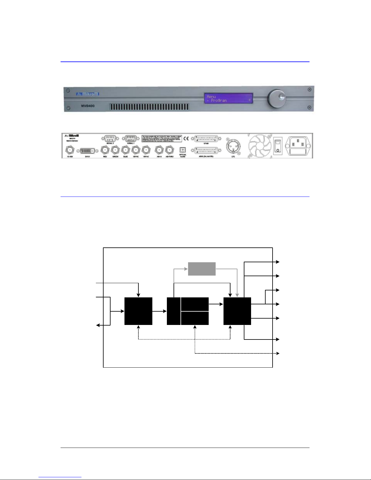
1.2 Front/Back View
Figure 1: Front view
Figure 2: Back view
1.3 Block Diagram
Pre-
processor
Post-
processor
Video
Decoder
µP
DMUX
RGBHV
DVI-D
HD-SDI
LTC
2 x RS232
ASI IN
ASI THRU
SPI IN
Audio
Decoder
4ch AES/EBU
TOSLink
MVD400
Audio Bitstream
Video
Figure 3: Block diagram

MikroM EMC Standard Compliance
MVD400 - User Manual 1.6 9/47
2 EMC Standard Compliance
The MVD400 complies with the following EMC standards:
CE
The MVD400 is in conformity with the following standards:
• EN 55103-1: 1997
• EN 55103-2: 1997
• EN 60335: 2001
FCC Part 15, Subpart B, Class A
This equipment has been tested and found to comply with the limits
for a Class A digital device, pursuant to Part 15 of the FCC Rules.
These limits are designed to provide reasonable protection against
harmful interference when the equipment is operated in a
commercial environment. This equipment generates, uses, and can
radiate radio frequency energy and, if not installed and used in
accordance with the instruction manual, may cause harmful
interference to radio communications. Operation of this equipment in
a residential area is likely to cause harmful interference in which
case the user will be required to correct the interference at his
expense.
ICES-003
This Class A digital apparatus complies with Canadian ICES-003.

Getting Started MikroM
10/47 1.6 MVD400 - User Manual
3 Getting Started
First, check if all devices are switched off before connecting to avoid
damages of any devices.
3.1 Transport Stream Interfaces
The MVD400 needs to be connected with a transport stream source.
The default input interface for the transport stream is the ASI-IN
interface. The ASI-THRU port can be used to forward the same
transport stream to additional devices (e.g. a second MVD400). If
you want to use the SPI interface, you have to change the
configuration of the MVD400 (Menu > Setup > Input) and use the
optionally available DVB-SPI cable.
3.2 Video Interfaces
Depending on the video cable type and your display’s interfaces you
have one of these possibilities to connect the MVD400 to your
display:
• 5xBNC/5xBNC or 5xBNC/VGA
Typical display units (CRT, TFT, plasma display, projector)
have at least one VGA or 5xBNC analog input which can be
connected with the corresponding cable type.
• DVI-D
Typical display types with a digital DVI-D input are TFT,
plasma display and projector. Digital is preferred to analog
connection, although some displays may have different
format capabilities between analog and digital input and
therefore choosing analog input may be more convenient.

MikroM Getting Started
MVD400 - User Manual 1.6 11/47
• HD-SDI
This interface type is used in professional environments.
Typical devices connected via HD-SDI are high quality
projectors (e.g. for cinematic environments) or detached
Digital-Analog-Converters (DAC).
The default output interface is the RGB-HV interface with Sync-onGreen enabled and color space set to RGB. To use the DVI-D or the
HD-SDI interface, please change the MVD400 configuration. (Menu
> Setup > Video > Output)
Note: Most displays only support a small subset of the display
modes supported by the MVD400. Please refer chapter 4.4.1
for details.
3.3 Audio Interface
The MVD400 has an optical audio interface and an AES3/EBU
interface. The optical audio interface provides the full bit stream or
optionally the decoded stereo signal. If the transport stream contains
more than two channels of uncompressed audio, the AES3 interface
has to be used to access all channels. (See chapter 4.5 for details)
3.4 Linear Time Code (LTC)
The LTC interface is used to synchronize the decoded content with
external devices such as time code displays or encoder systems and
can be connected with an optionally available cable. It conforms to
the SMPTE standard Time and Control Code (SMPTE 12M).
3.5 Line Cord Plug
After all connections are ready you can plug in the line cord and
switch on the system. Power supply must be in range of 100-240
VAC with 50/60 Hz.

Functional Description MikroM
12/47 1.6 MVD400 - User Manual
4 Functional Description
The MVD400 is an integrated HDTV decoder, complying with the
MPEG-2 MP@HL standard (ISO/IEC13818), which is adopted
worldwide in broadcast.
It receives compressed MPEG-2 Transport Stream data from
ASI/SPI interface and outputs decompressed video onto RGB-HV,
DVI-D or HD-SDI interface as well as synchronous audio to TOS
Link and/or 4ch AES/EBU. Time code information (LTC) is extracted
from the Transport Stream and output synchronously to the
audio/video output. Several MVD400 can be daisy-chained via
RS232 to be managed by a single RS232 port of one controlling PC.
Transport Stream Demultiplexing, Video Decoding and Audio
Processing together with a RISC CPU are incorporated in a single
chip called “HiPEG+”, being the key component of the MVD400. Due
to the unique design of this chip, the RISC CPU basically is in charge
of power-up configuration and some run-time support only. The
remaining processor performance is used to make the decoder
device user-friendly with the support of several automatic
mechanisms like “Automatic Program Detection”. The firmware of the
decoder can be upgraded via RS232 and stored resident to the
internal FLASH memory as well as individual settings.
Custom-specific functions can be added easily via firmware upgrade
due to the internal structure using programmable hardware (FPGA)
located before and after the decoder in the data path, which together with the built-in processor – establishes a powerful,
extensible HD decoder platform.
4.1 Preprocessor
The preprocessor in the MVD400 serves the following functions:
• Multiplexer between ASI and SPI source inputs
• TS buffer and sync signal generator

MikroM Functional Description
MVD400 - User Manual 1.6 13/47
4.2 Postprocessor
The postprocessor in the MVD400 serves the following functions:
• RGB/YUV router to different video output ports
• Audio S/P-DIF and AES/EBU format generator
• Time code generator
4.3 Demultiplexing and Program Detection
In the HiPEG+ chip Transport Stream Demultiplexing is performed by
a combination of demultiplexing hardware (for low level bit stream
operations) and CPU based software processing. All relevant
audio/video parameters are extracted from the Transport Stream to
configure embedded and non-embedded devices automatically.
For Automatic Program Detection & Selection the system scans the
Transport Stream, recognizing available programs from the
PAT/PMT tables, which then can be selected from the menu or from
remote. Program name information as used in DVB and ATSC data
streams are extracted as well. ATSC program names are preceded
by the major and minor channel number. The ordering of the
program list corresponds to the appearance in the PAT. Additionally,
one manual program with static PIDs can be defined individually.
A loss of transport stream is detectable and is interpreting as unplug
of the transport stream source. In this case, the active program is
reset to Program 1 and next time a transport stream is available
again it gets rescanned for programs.
4.4 Video Decoding and Video Output
The video decoder part within the HiPEG+ chip is implemented by
dedicated hardware to obtain maximum performance without the
need of real-time support from the RISC CPU.

Functional Description MikroM
14/47 1.6 MVD400 - User Manual
Performance and memory of the video decoder allows decoding of
video up to 1920x1080 Pixel at 30 Hz progressive, which is
equivalent to 1920x1080 Pixel at 60 Hz interlace.
Data streams are input as MPEG-2 Transport Streams, which may
contain video elementary streams with an application-proven bit rate
of up to 80 Mbps. There are no constraints regarding the video
format at this bit rate.
The output format of the video is selected automatically, depending
on the resolution and frame rate of the video elementary stream and
the display capabilities list (see chapter 4.4.2), the best matching
video output format is selected automatically. The resolution
information of the video elementary stream is also used to compute
offsets and scale factors depending on the currently selected scale
mode (see chapter 4.4.4).
Additionally, for the analog output the color space and the sync
mode can be selected.
4.4.1 Video Output Formats
The MVD400 generates the most common video output formats for
SDTV, ATV and HDTV resolution video.
A standard set of video output formats is delivered with the device as
listed in Table 1. However, custom-specific formats can be adopted
on request.
Some formats have two alternatives with slightly different timing
parameters, e.g. 1080/24sf (1125) and 1080/24sf (1250). The first
format has 1125 lines/frame and a horizontal frequency of 27 kHz,
the second one has 1250 lines/frame and a horizontal frequency of
30 kHz. Since some displays cannot handle video with horizontal
frequency below 30 kHz, select 1080/24sf (1250) in the Display
Capability List to display 1080/24sf.

MikroM Functional Description
MVD400 - User Manual 1.6 15/47
Menu Reference
Sample
per active
line
Active
line per
frame
Frame
Rate
Sampling
frequency
Samples
per total
line
Total lines
per frame
Line
rate
Pixel Pixel Hz MHz Pixel Pixel kHz
1080/24p(1125)†
SMPTE274M
Tab 1.10
1920 1080 24p 74.25 2750 1125 27.000
1080/24sf(1125)†
1920 1080 24p 74.25 2750 1125 27.000
1080/24sf(1250)†
1920 1080 24p 74.25 2475 1250 30.000
1080/25p(1125)
SMPTE274M
Tab 1.9
1920 1080 25p 74.25 2640 1125 28.125
1080/50i(1125)‡
SMPTE274M
Tab 1.6
1920 1080 25i 74.25 2640 1125 28.125
1080/50i(1250)‡
SMPTE295
Tab 1.2
1920 1080 25i 74.25 2376 1250 31.250
1080/30p(1125)
SMPTE274M
Tab 1.7
1920 1080 30p 74.25 2200 1125 33.750
1080/60i(1125)
SMPTE274M
Tab 1.4
1920 1080 30i 74.25 2200 1125 33.750
720/60p(750)
SMPTE296
Tab 1.1
1280 720 60p 74.25 1650 750 45.000
576/50i(625)
720 576 25i 13.5 864 625 15.625
576/50p(625)
720 576 50p 27.0 864 625 31.250
480/60i(525)
720 483 29.97i 13.5 858 525 15.734
480/60p(525)
SMPTE293M
Tab 1
720 483 59.94p 27.0 858 525 31.468
Table 1: Video Output Formats / Display Capability List
†
These modes are mutual exclusive selectable.
‡
These modes are mutual exclusive selectable.

Functional Description MikroM
16/47 1.6 MVD400 - User Manual
4.4.2 Display Capabilities
Different displays support different horizontal and vertical
frequencies. This results in different video formats which can be
supported by the display. The display capabilities mask is used to
mark video modes displayable by the connected display.
To ease definition of this mask for a connected display use
MVD400’s test picture facility: Step-by-step activate test picture for
all video output formats and check for correct display of the color
boxes (each has a size of 256x256 pixel). Afterwards, enable only
correctly displayed output formats in the mask.
Once this mask is defined for a given display the MVD400 will only
choose the enabled (resp. marked) video output formats (see
chapter 4.4.3). Please note that these changes are non-resident as
long as they have not been stored into the flash memory by saving
the configuration.
4.4.3 Video Format Selection Algorithm
The video format selection automatically chooses a video output
format by a set of given rules. Starting with all enabled video modes
from the display capabilities list, criteria’s to miss video modes out
are:
• Frame rate of video stream and frame rate of video mode
does not match. Frame rates which only differ in 1000/1001
clock division (e.g. 30 Hz resp. 29.97 Hz) are considered to
be compatible.
• Scan type of video stream is interlaced and scan type of
video mode is progressive (i.e. interlaced videos can not be
output progressive).
Afterwards, if there is more than one video mode left the choice is
made by comparing resolutions. The video modes with bigger
resolutions than the video stream are preferably selected, since they
can show the whole video content without scaling.
The selection algorithm is independent of the selected scale mode.

MikroM Functional Description
MVD400 - User Manual 1.6 17/47
4.4.4 Scale Modes
With each change in video resolution, video mode or scale mode
selection the scaler engine gets reinitialized. Scale modes can be
selected in (Menu > Setup > Video > Scale).
Keep in mind that scaling - in particular vertical scaling - may results
in lower image quality since pixels have to be interpolated. In case
that video resolution is lower than video mode resolution the empty
screen areas are black. Except in Disabled mode all modes center
the image onto the screen.
The MVD400 supports 9 different scale modes:
1. Disabled
This mode does not scale the video at all. Video output is native
and bound to upper left corner.
2. Center wo/ ratio
This mode does not scale the video at all. Video output is native
and centered.
3. Center w/ ratio
This mode scales video only in horizontal direction to meet the
aspect ratio constraints. Vertical scaling is avoided.
4. Double w/ ratio
This mode scales video in vertical direction by factor 2 (doubles
the size) and scales in horizontal direction to meet the aspect
ratio constraints. This mode is useful to output a SD clip on an
HD screen.
5. Fit x w/ ratio
This mode scales the image horizontally to fill the whole width of
the output format and scales vertically to fulfil a correct aspect
ratio. Because of vertical scaling the image has an inferior quality
compared with the modes above.
6. Fit y w/ ratio
This mode scales the image vertically to fill the whole height of
the output format and scales horizontally to fulfil a correct aspect

Functional Description MikroM
18/47 1.6 MVD400 - User Manual
ratio. Because of vertical scaling the image has an inferior quality
compared with the modes above.
7. Fit x wo/ ratio
This mode scales the image horizontally to fill the whole width of
the output format, but does not scale vertically. Therefore, aspect
ratio may be incorrect.
8. Fit y wo/ ratio
This mode scales the image vertically to fill the whole height of
the output format, but does not scale horizontally. Therefore,
aspect ratio may be incorrect.
9. Fit xy wo/ ratio
In this mode the image is scaled in both directions fit the output
format exactly. Therefore, aspect ratio may be incorrect.
4.5 Audio Processing
The MVD400 supports extraction from transport stream of the
following audio formats:
• MPEG-1 Layer 1, MPEG-1 Layer 2, MPEG-2 multi-channel
• Dolby AC-3 Stereo, Dolby AC-3 5.1, Dolby E
• 8 channel SMPTE 302M (24 Bit, 48 kHz)
With the optional available audio decoder the compressed audio
formats can be decoded and output as PCM audio.
The audio format is detected automatically and audio output is
configured accordingly. Table 2 shows the audio output configuration
for compressed and uncompressed audio formats.

MikroM Functional Description
MVD400 - User Manual 1.6 19/47
Optical TOSLink
8 ch electrical
AES/EBU
S/P-DIF @ TOSLink 8 ch AES/EBU @ DSUB25
Compressed Audio Bit stream Bit stream on Ch. 1-2
Uncompressed Audio
Lin. PCM, Ch. 1-2 Lin. PCM, Ch. 1-8
Table 2: Audio Output Configuration
Channel 1-2 of the uncompressed audio (SMPTE 302M) is output to
the TOSLink connector with an enabled copyright bit. This allows the
usage of consumer receivers, but prevents copyright violations.
Note: Single- or multi-channel uncompressed audio (1 to 8
channel SMPTE 302M) must use a single
Transport
Stream PID.
4.5.1 Audio Delay
The audio bit stream is output synchronously to the video, optional
with a delay (to compensate an external audio or video delay). The
delay could be selected either as a time value between -40 and 200
ms in steps of 1 millisecond or by a number of frames, which can be
calculated into one another with the frame rate of the current video.
4.5.2 Audio Decoder (optional)
The MVD400 is offered with an optional audio decoder onboard.
Customer can select between two different options of audio decoding
as listed in Table 3.

Functional Description MikroM
20/47 1.6 MVD400 - User Manual
Order-Code Audio Decoding Standards Audio post-processing
MVD400-AD1
• MPEG-2 Layer 2 Stereo
• MPEG-2 Layer 2 multi
channel
• MPEG-2 Layer 3 (MP3)
• DTS
• Dolby ProLogic
• Dolby ProLogic II
• Equalizer
MVD400-AD2
• MPEG-2 Layer 2 Stereo
• MPEG-2 Layer 2 multi
channel
• Dolby AC-3 Stereo
• Dolby AC-3 5.1 Stereo down
mix
• AAC Stereo
• DTS
• Dolby ProLogic
• Dolby ProLogic II
• Equalizer
Table 3: Audio Decoder Options
Note: Depending on the application separate license
agreements may be needed. Contact
sales@mikrom.com for details.
4.6 Functional Extensions (Custom-specific)
Since the system includes hardware programmable pre- and post
processors (FPGA) a number of custom extensions are possible.
Example functions are:
• Transport Stream Descrambling/Decryption
• Meta-data extraction from Transport Stream and insertion
into audio/video
• Video Scrambling/Encryption
• Logo insertion
• Subtitling
• Hardware-Extension with custom-specific add-on board

MikroM Decoder Control
MVD400 - User Manual 1.6 21/47
5 Decoder Control
Configuration and control of the MVD400 decoder is established
either from the
• Front panel with its panel display and jog dial, or from a
• Remote PC with a RS232 connection using
o MSCP which is a transport protocol allowing to
control one or more MVD400 units from a single
RS232 port (additional MVD400’s must be chain
linked with null modem cable)
o a Terminal program which works as an emulation of
front panel display and jog dial
5.1 User Mode And Administrator Mode
The MVD400 has two operating modes. In the User Mode no vital
settings of the MVD400 can be changed. The Administrator Mode is
for testing and configuring the MVD400. To change from the User
Mode to the Administrator Mode a password is needed. The default
password after shipping is “2”.
Note: It is strongly recommended to change this password if the
MVD400 is used in an environment where unauthorized
people have access to the box.
5.2 Front Panel Control / Panel Emulation
The front panel of the MVD400 features a 2x20 character liquid
crystal display and a jog dial.
The jog dial is used to navigate through the menu, to select functions
and enter values with visual feedback on the display. A terminal
program on e connected computer can be used as front panel
emulation, since the content of the display is shown in the terminal
window and the keyboard is used as jog dial.

Decoder Control MikroM
22/47 1.6 MVD400 - User Manual
After an adjustable timeout the display cycles status information and
a menu to control the MVD400.
5.2.1 Menu Navigation
In the first row of the display the name of the current menu is
displayed. In the second row the items of the current menu are listed
and can be shifted by turning the jog dial. The symbols in the most
left/right position of the second row indicate the end of list (the dot)
resp. the list continuation (arrow).
Jog-dial Terminal Program Action
Turn left Arrow left
Change to the previous menu
entry
Turn right Arrow right Change to the next menu entry
Press short
Arrow down
or enter
Enter current menu and reveal
sub menu
Press long
(>1 second)
Arrow up
or backspace
Leave the current menu and get
back to the parent menu
All sub menus have a back entry on either end of the menu list,
which also can be selected to get back to the parent menu.

MikroM Decoder Control
MVD400 - User Manual 1.6 23/47
5.2.2 Selecting Checkboxes and Radio Buttons
A checkbox can be selected or unselected by shortly pressing the
jog-dial or by pressing the arrow down key or enter on the terminal
program.
A radio button entry can be selected in the same way, but unlike
checkboxes, all other items in the list are unselected.
Please note that radio button entries could have sub menus. To
enter these sub menus, it is necessary to select the radio button and
then again press the jog-dial, the arrow down key or the enter key to
enter this menu.
The display capabilities list is somehow an exception, since it is
organized as check boxes, but in certain items behave like radio
buttons. There are video modes which are only exclusively
selectable in their group, as marked in Table 1 with a taller line.
5.2.3 Entering Numbers
When you start to edit a number you have the possibility to enter a
number directly by turning the jog dial. This entering mode is
suggested for small changes of the number. Turning to the right will
increment the number; turning to the left will decrement it.
After pressing the jog-dial, a checkmark appears and you are now in
single-digit editing mode. In this mode, the number can be changed
digit by digit. This mode is suggested to change large value ranges
more quickly. Only the most right digit can be edited respectively.
Selecting the left arrow symbol, the most right digit is deleted. The
cursor will go back one digit and you can change this one by turning
the jog dial. To add this digit simply press the jog dial. If the entered
number is the right one, simply press the jog-dial on the check mark
to confirm input.
If the input of the number has to be aborted, choose the asterisk and
press the jog dial or press the jog dial for more than one second on
any character.
If the box is remote controlled with a terminal program, the numbers
can be edited with the number keys and backspace/enter.

Decoder Control MikroM
24/47 1.6 MVD400 - User Manual
5.2.4 Entering Strings and Passwords
Strings and passwords can be edited in the same way like numbers.
You get back to a previous character with the arrow left, confirm the
string with the check mark and cancel the input with the asterisk.
If a password is entered, the previous characters are represented by
asterisks. The only character which is shown is the one which is
currently edited.
5.3 MSCP
MSCP is the abbreviation for MikroM Serial Communication Protocol.
This protocol can be used for remote controlling the MVD400 (or a
chain of MVD400’s) with a singe computer program. Nearly all
functions of the MVD400 are accessible with MSCP commands.
For details to the MSCP specification, please contact us.

MikroM Decoder Control
MVD400 - User Manual 1.6 25/47
5.4 Menu Structure
Input
Vide o
Audio
Cont rol
Load /Save Confi g
Setup
System
Status
St at i st i cs
Ve rs i o n Nu mbe r s
Rese t
Updat e
Audio Type
PCM/302M
AC-3
MPEG1- L2
Program
Prog ram 1
Prog ram 2
...
Prog ram 19
Fixed PIDs
Resc an Progra ms
Main Menu
Prog ram
Setup
System
Fixed PIDs
Video PID
Audio PID
Audio Type
PCR PID
Status
Input
Vide o
Audio
Temperature
St at i st i cs
Reset
System Reset
Deco der Reset
Audi o Reset
cont inued on nex t page

Decoder Control MikroM
26/47 1.6 MVD400 - User Manual
Display Cap .
1080 /24p(1125 )
1080 /24sf( 1125)
1080 /24sf( 1250)
1080 /25p(1125 )
1080 /50i( 1125)
1080 /50i( 1250)
1080 /30p(1125 )
1080 /60i( 1125)
720/ 60p(75 0)
576/ 50i(6 25)
576/ 50p(62 5)
480/ 60i(5 25)
480/ 60p(52 5)
Test Pattern
None
1080 /24p(1125 )
1080 /24sf( 1125)
1080 /24sf( 1250)
1080 /25p(1125 )
1080 /50i( 1125)
1080 /50i( 1250)
1080 /30p(1125 )
1080 /60i( 1125)
720/ 60p(75 0)
576/ 50i(6 25)
576/ 50p(62 5)
480/ 60i(5 25)
480/ 60p(52 5)
Scale
Disabled
Center wo/ ratio
Cent er w/ rati o
Doubl e w/ ratio
Fit x w/ ratio
Fit y w/ ratio
Fit x wo/ ratio
Fit y wo/ ratio
Fit xy wo/ ratio
Input
ASI
SPI
Video
Outp ut
Display Cap.
Scal e
Test Pattern
Audio
Decode AC3
Decode MPG
Audi o Delay
302M Co nsumer
Audio Delay
Unit
Val u e
Unit
Frame s
Milliseconds
Output
HD-SDI
DVI
Anal og
Control
Menu Timeout
OnScreen Menu
Seri al 1
Seri al 2
Admin Mode
Admi n Password
Serial 1/2
MSCP
Te r m i n a l
Even t Log
Baud Rate
Baud Rate
9600
1920 0
3840 0
5760 0
11 52 00
Load/Save Config
Save
Load
Load Defaul ts
Eras e Config
Input
Vide o
Audi o
Control
Load/S ave Config
Setup
5.5 Serial Connection
For remote control the serial port of the PC (e.g. COM1) has to be
connected with port “Serial 1” of the MVD400 with the attached serial
cable. Additionally, each port “Serial 2” could be connected to port
“Serial 1” of the next system via null modem cable to establish a
configuration chain. Each port can be configured individually as one
of:
• MSCP
MSCP is the mode in which a control program on the host
PC can control and configure up to 64 MVD400 devices in
the serial chain. To use this each port in the chain must be
configured as MSCP.

MikroM Decoder Control
MVD400 - User Manual 1.6 27/47
• Terminal
This is the mode in which an attached terminal resp. terminal
program on the host PC can be used as front panel
emulation. Simultaneous controlling via terminal and front
panel is possible.
• Event Log
This serial port mode can be used to get detailed status
information on an attached terminal. The messages are
arranged in several levels. The minimum level, which has to
be shown is adjustable and is one of the levels "Logs",
"Infos", "Warnings", "Errors" and "Critical". By default, the log
level is set to the minimum level "Logs".
Default parameters for the serial ports are as follows:
• 38.400 Baud
• 8N1 (8 signal bits, no parity, 1 stop bit)
• Hardware handshake (RTS/CTS)
The baud rate is adjustable from 9600 baud to 115200 baud.
5.6 Terminal Software
A terminal program can be used as front panel emulation. This
chapter introduces several terminal programs for different operation
systems. These programs are not part of the distributed MVD400
software package.

Decoder Control MikroM
28/47 1.6 MVD400 - User Manual
5.6.1 HyperTerminal
The "HyperTerminal" program is part of the Microsoft Windows™
software packet.
5.6.1.1 Connection And Setup
1. Connect a serial port of the computer with the port "Serial 1"
of the MVD400 using the attached serial cable.
2. Start HyperTerminal with the setup file MVD400.ht.
3. Open menu File->Settings and select the serial port of the
computer which is used
4. Save your settings
5.6.1.2 Terminal Control
Turn MVD400 power on. Now the arrow keys can be used to
navigate through the menu. See chapter "Menu navigation" for
details.

MikroM Decoder Control
MVD400 - User Manual 1.6 29/47
5.6.1.3 Update Of The MVD400 Firmware
1. Open menu Transfer->Send File
2. Select the MVD400 image file
3. Select Xmodem protocol
4. Start upload with Send
5. By turning MVD400 power on, the automatic upload process is
started

Decoder Control MikroM
30/47 1.6 MVD400 - User Manual
6. After a successful update, the decoder loads the new firmware

MikroM Decoder Control
MVD400 - User Manual 1.6 31/47
5.6.2 ZOC
"ZOC" is a shareware terminal program, available at
http://www.emtec.com.
5.6.2.1 Connection And Setup
1. Connect a serial port of the computer with the port "Serial 1" of
the MVD400 using the attached serial cable.
2. Start ZOC
3. Open menu Options->Edit Session Profile
4. Choose the page "Device"
5. Select I/O-Device Serial/Modem
6. Select the serial port of the computer which is used
7. Select the serial port settings 38400, 8N1 and RTS/CTS
handshake
8. Choose the page "Transfer"
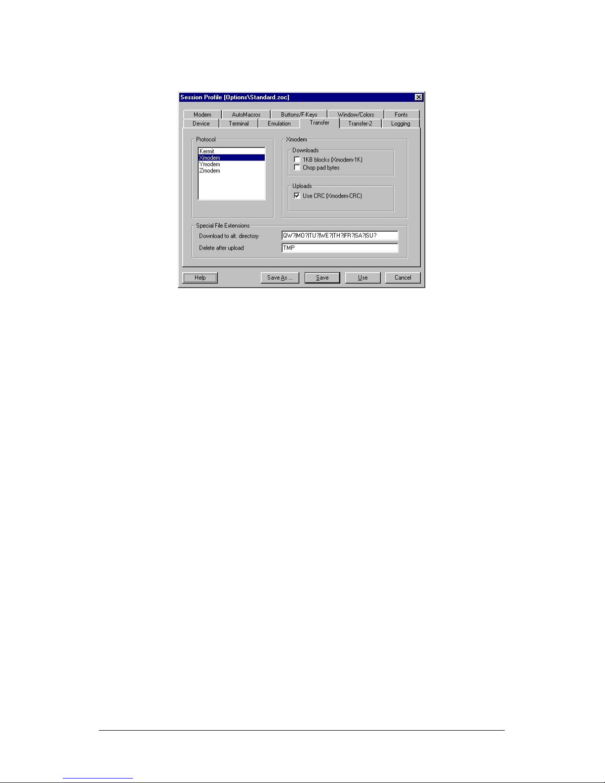
Decoder Control MikroM
32/47 1.6 MVD400 - User Manual
9. Select the protocol Xmodem and activate "Use CRC"
10. Save your settings
5.6.2.2 Terminal Control
Turn MVD400 power on. Now the arrow keys can be used to
navigate through the menu. See chapter "Menu navigation" for
details.

MikroM Decoder Control
MVD400 - User Manual 1.6 33/47
5.6.2.3 Update Of The MVD400 Firmware
1. Open menu Transfer->Upload...
2. Select the MVD400 image file and press the open button
3. By turning MVD400 power on, the automatic upload process is
started
4. After a successful update, the decoder loads the new firmware
Decoder Control MikroM
34/47 1.6 MVD400 - User Manual
5.6.3 Minicom
The "minicom" program is part of many Linux distributions and can
be downloaded from http://alioth.debian.org/projects/minicom/.
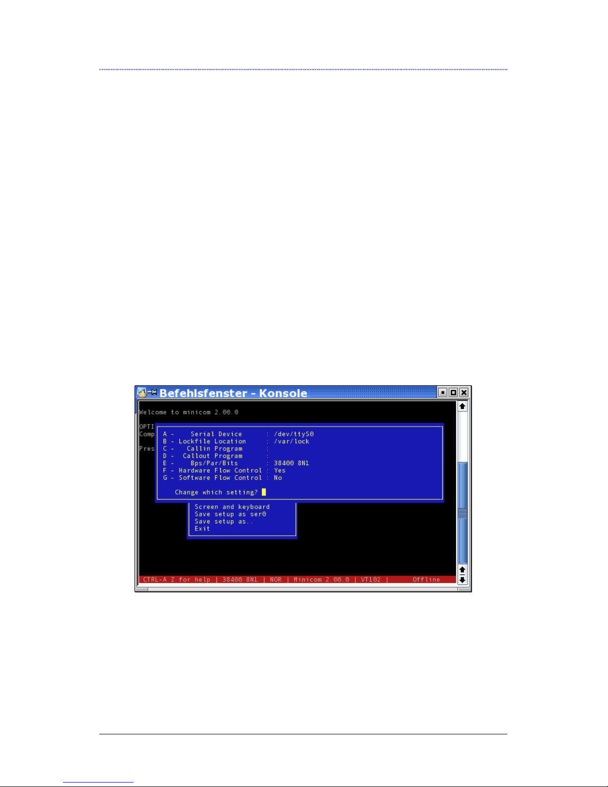
5.6.3.1 Connection And Setup
1. Connect a serial port of the computer with the port "Serial 1" of
the MVD400 using the attached serial cable.
2. Start minicom as root
3. Open the config menu by Ctrl-A o
4. Choose "Serial port setup"
5. Select the serial port of the computer which is used (/dev/ttyS0,
for example)
6. Select the serial port settings 38400 Baud, 8N1 and Hardware
Flow Control
7. Save these settings

MikroM Decoder Control
MVD400 - User Manual 1.6 35/47
5.6.3.2 Terminal Control
Turn MVD400 power on. Now the arrow keys can be used to
navigate through the menu. See chapter "Menu navigation" for
details.
5.6.3.3 Update Of The MVD400 Firmware
1. Open the upload menu by Ctrl-A s
2. Select xmodem
3. Select the MVD400 image file with the space bar and than press
enter

Decoder Control MikroM
36/47 1.6 MVD400 - User Manual
4. By turning MVD400 power on, the automatic upload process is
started
5. After a successful update, the decoder loads the new firmware

MikroM Technical Information
MVD400 - User Manual 1.6 37/47
6 Technical Information
6.1 Mechanical
• Height 44.5 mm (1.8”, 1RU)
• Depth 290 mm (11.4”)
• Width 484 mm (19”)
• Weight 2.6 kg (5.7 lbs) typical
• Cooling back side fan, side-to-side
6.2 Power
• Voltage 100 to 240 V, 50/60 Hz
• Consumption < 50 VA
6.3 Environmental
• Operating temperature 0°C to 40°C (32°F to
104°F)
• Relative humidity 5 to 90% non-condensing
6.4 Safety
• Approvals CE, FCC, CSA

Technical Information MikroM
38/47 1.6 MVD400 - User Manual
6.5 Transport Stream Interfaces
• SPI-IN (1 x DSUB25 Female)
• ASI-IN (1 x BNC)
• ASI-THRU (1 x BNC)
6.6 Video Input Format
• Transport Stream (ISO/IEC 1318-1)
• MPEG-2 (ISO/IEC 1318-2) up to MP@HL
• Video bit rate up to 80 Mbps
6.7 Video Output Interfaces
• HD-SDI (1 x BNC, 75 Ohm) (SMPTE292M)
• DVI-D (TMDS)
• Analog (5 x BNC, 75 Ohm)
o RGB-HV or YUV (SMPTE274M, SMPTE293M,
SMPTE296M)
o Sync on green, Sync on all or HV
6.8 Video Output Formats
• 1920 x 1080, 24p (1125)
• 1920 x 1080, 24sf (1125)
• 1920 x 1080, 24sf (1250)
• 1920 x 1080, 25p (1125)
• 1920 x 1080, 50i (1125)

MikroM Technical Information
MVD400 - User Manual 1.6 39/47
• 1920 x 1080, 50i (1250)
• 1920 x 1080, 30p (1125)
• 1920 x 1080, 60i (1125)
• 1280 x 720, 60p (750)
• 720 x 576, 50i (625)
• 720 x 576, 50p (625)
• 720 x 480, 60i (525)
• 720 x 480, 60p (525)
6.9 Audio Output Interfaces
• S/P-DIF Optical (TOSLink)
• 4 x AES/EBU (DSUB25 female, 2.3V pp, 110 Ω)
6.10 Audio Output Formats
• Compressed Audio (Pass-through)
o MPEG 1/2 up to 448 kbps
o Dolby AC-3 up to 640 kbps
o Dolby E
• Uncompressed Audio (Pass-through)
o PCM (SMPTE302M) up to 8 channels, 10.7 Mbps
• Decoded Audio (optional)
o MPEG-2 Layer 1, MPEG-2 Layer 2, MP3 (MPEG-2
Layer 3)
o Dolby AC-3 (Stereo downmix)

Technical Information MikroM
40/47 1.6 MVD400 - User Manual
6.11 Control
• Local
o Front panel display and jog dial
• Remote (1 x DSUB9 male RS232, 1 x DSUB9 female
RS232)
o Terminal Mode (Front panel emulation)
o MSCP Mode (Multi-Decoder control from single
RS232)
• Firmware upgrade via XModem
• Event log on serial connected terminal

MikroM Connectors
MVD400 - User Manual 1.6 41/47
7 Connectors
7.1 ASI-IN
Connector: BNC
Input signal: 800 mV p-p, 75 Ω
7.2 ASI-THRU
Connector: BNC
Output signal: 800 mV p-p, 75 Ω
Connectors MikroM
42/47 1.6 MVD400 - User Manual
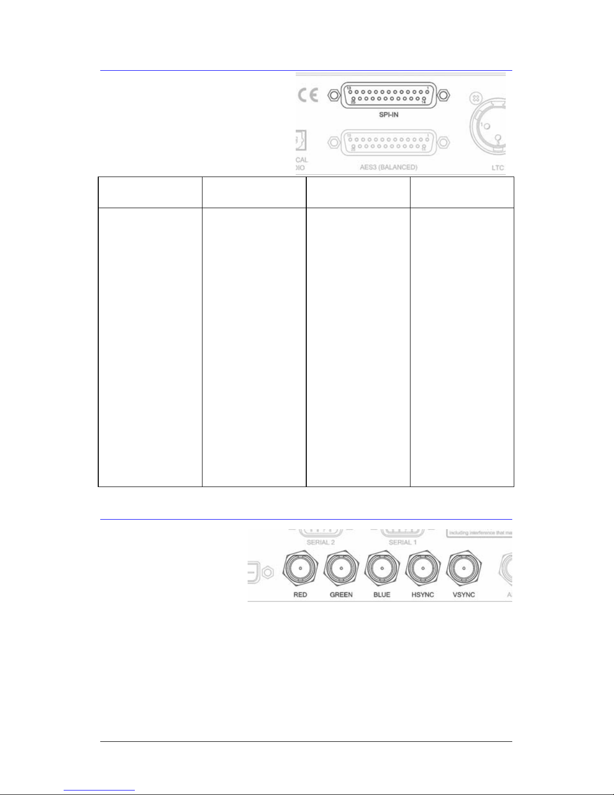
7.3 SPI-IN
Connector: DSUB25 Female
Input signal: LVDS, 100 Ω
Pin Signal Pin Signal
1 Clock+ 14 Clock-
2 System GND 15 System GND
3 Data7+ (MSB) 16 Data7- (MSB)
4 Data6+ 17 Data6-
5 Data5+ 18 Data5-
6 Data4+ 19 Data4-
7 Data3+ 20 Data3-
8 Data2+ 21 Data2-
9 Data1+ 22 Data1-
10 Data0+ 23 Data0-
11 DataValid+ 24 DataValid-
12 PSync+ 25 PSync-
13 Cable Shield
7.4 RGB-HV
Connector: 5 x BNC
Output signal:
3 x 1 V p-p, 75 Ω (RGB)
2 x TTL (HV)

MikroM Connectors
MVD400 - User Manual 1.6 43/47
7.5 DVI
Connector: DVI-D Female
Output signal: TMDS
Pin Signal Pin Signal
1 Data2- 13 Data3+
2 Data2+ 14 +5V Power
3 Data2/4 Shield 15 GND (for +5V)
4 Data4- 16 Hot Plug Detect
5 Data4+ 17 Data0-
6 DDC Clock 18 Data0+
7 DDC Data 19 Data0/5 Shield
8 Not connected 20 Data5-
9 Data1- 21 Data5+
10 Data1+ 22 Clock Shield
11 Data1/3 Shield 23 Clock+
12 Data3- 24 Clock-

Connectors MikroM
44/47 1.6 MVD400 - User Manual
7.6 AES3 (Balanced)
Standard: AES3/1992
Connector: DSUB25 Female
Output signal: 2 to 5 V, 110 Ω
Pin Signal Pin Signal
1 Channel3+ 14 Channel3-
2 Channel3 GND 15 Channel2+
3 Channel2- 16 Channel2 GND
4 Channel1+ 17 Channel1-
5 Channel1 GND 18 Channel0+
6 Channel0- 19 Channel0 GND
7 NC 20 NC
8 NC 21 NC
9 NC 22 NC
10 NC 23 NC
11 NC 24 NC
12 NC 25 NC
13 NC
7.7 HD-SDI
Connector: BNC
Output signal: 800 mV p-p, 75 Ω
MikroM Connectors
MVD400 - User Manual 1.6 45/47
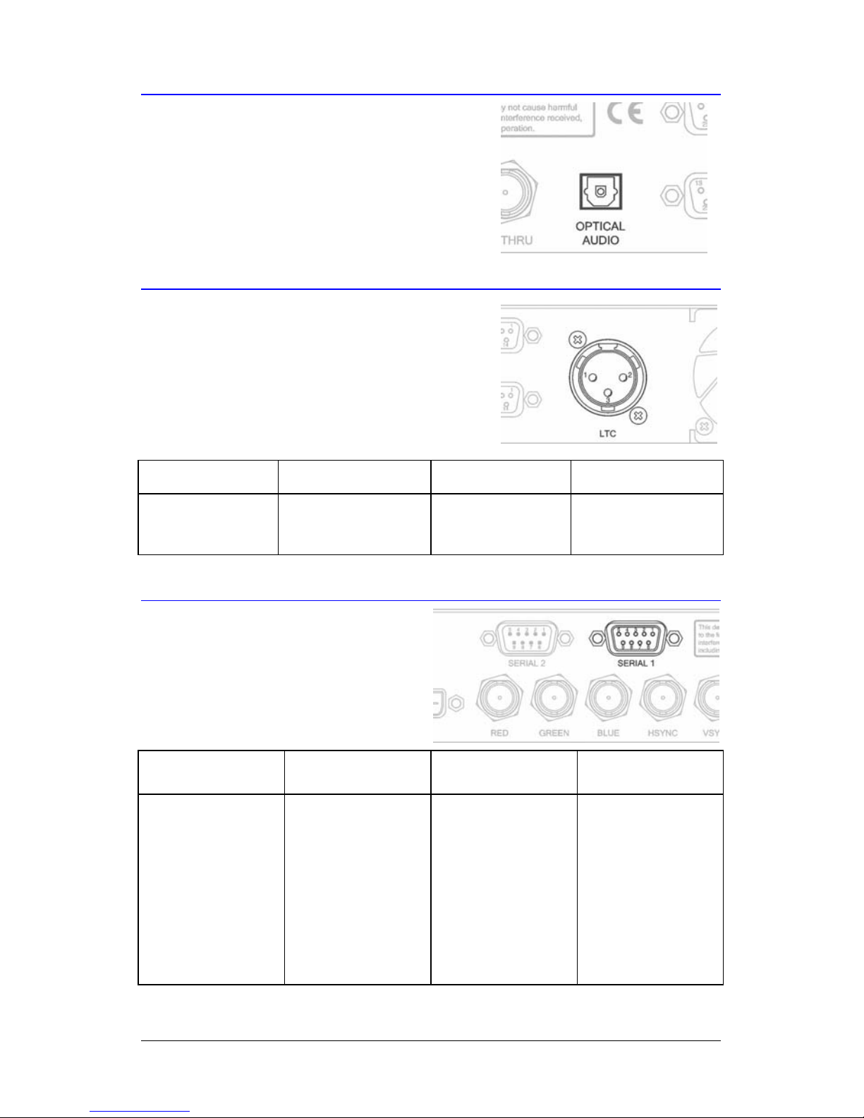
7.8 Optical Audio
Connector: TOSLink Female
Output signal: Optical
7.9 LTC
Connector: XLR Male
Output signal: max. 4.5 V, 30 Ω
Pin Signal Pin Signal
1 GND 3 Signal-
2 Signal+
7.10 Serial 1
Standard: RS232
Connector: DSUB9 Male
Pin Signal Pin Signal
1
Data Carrier
Detect
6 Data Set Ready
2 Receive Data 7 Request To Send
3 Transmit Data 8 Clear To Send
4
Data Terminal
Ready
9 Ring Indicator
5 Signal GND

Connectors MikroM
46/47 1.6 MVD400 - User Manual
7.11 Serial 2
Standard: RS232
Connector: DSUB9 Female
Pin Signal Pin Signal
1
Data Carrier
Detect
6 Data Set Ready
2 Receive Data 7 Request To Send
3 Transmit Data 8 Clear To Send
4
Data Terminal
Ready
9 Ring Indicator
5 Signal GND

MikroM Support
MVD400 - User Manual 1.6 47/47
8 Support
If you encounter problems with installing or using the MVD400,
please contact us at the address below.
MikroM GmbH
Dovestr. 1, 10587 Berlin, Germany
Tel: +49 30 398839-0
E-Mail: support@mikrom.com
 Loading...