

Page 1

Installation and Operating manual
Ethos 28cc
Ultra High Efficiency Gas Fired
Condensing Combination Boiler
Page 2

Contents
1. Why choose Mikrofill?................................ 6
2. Safety Considerations................................ 7
3. Symbols .................................................... 7
3.1 Gas Safety................................................... 7
4. Electrical Supply........................................7
5. Terms of Warranty..................................... 8
6. Commissioning Certificate ......................... 8
6.1 Requirements for the system quality............. 8
7. Existing Installations .................................. 8
7.1 Considerations prior to Connection............... 8
7.2 Expansion Vessels9
8. Introduction................................................ 9
8.1 Variable Controlled Output. .......................... 9
8.2 Emissions.................................................... 9
8.3 PPS Plastic Flue System.............................. 9
8.4 Approvals .................................................... 9
8.5 Additional Features...................................... 9
9. Description of Appliances......................... 10
9.1 EC 16, 23, 31 and 38 H.............................. 10
9.2 EC 16, 23, 31 and 38 HS............................ 10
9.3 EC 16, 23, 31 and 38 S.............................. 10
10. Technical Information............................. 11
11. Main Component Specification............... 13
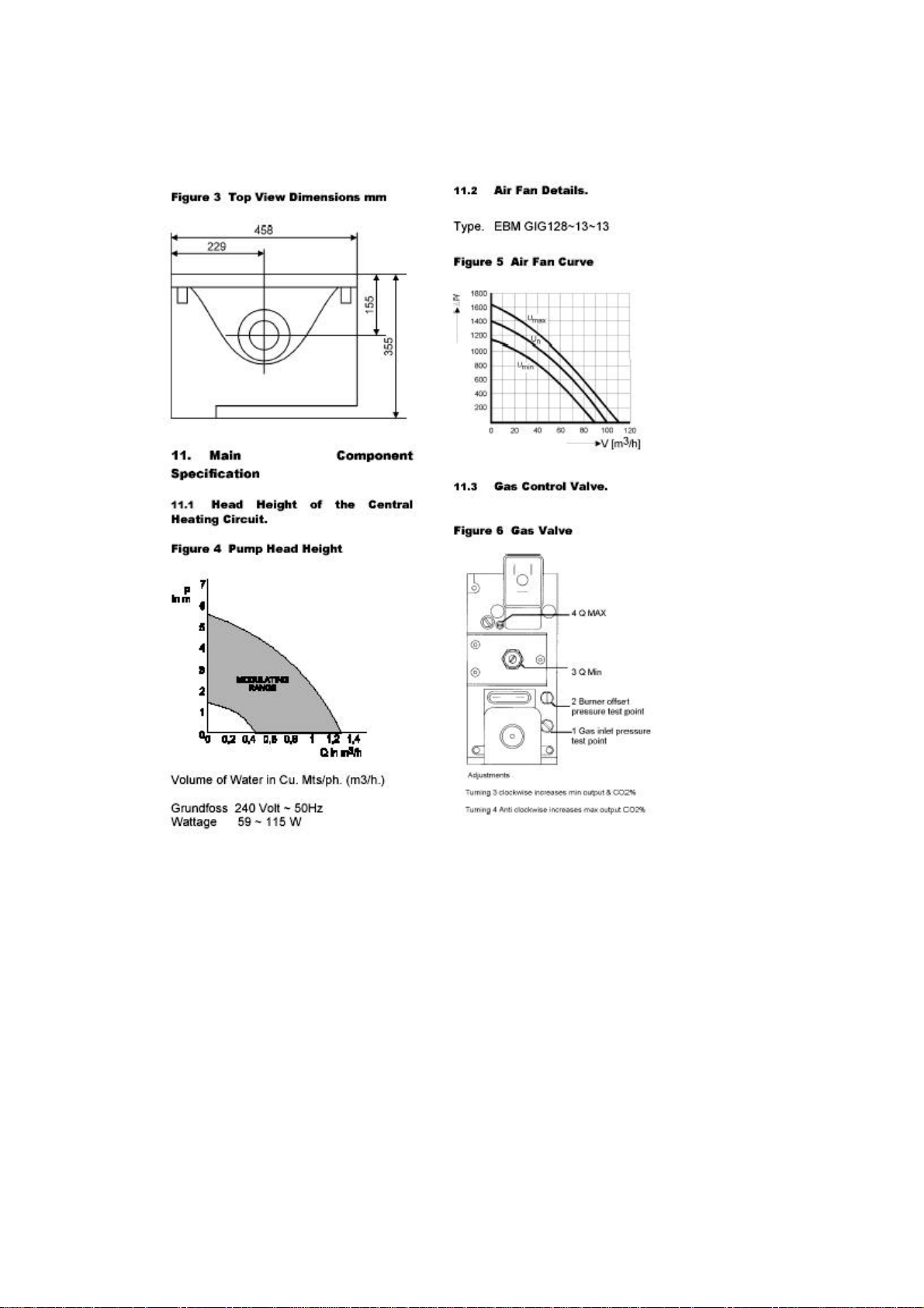
11.1 Head Height of the Central Heating Circuit.13
11.2 Air Fan Details......................................... 13
11.3 Gas Control Valve.................................... 13
12. Unpacking & Items Supplied .................. 14
13. Accessories........................................... 14
14. Operation............................................... 15
14.1 Variable Controlled Output ....................... 15
14.2 Variable pump.......................................... 15
14.3 Frost Protection........................................ 15
14.4 Year Long Protection................................ 15
15. Siting the Appliance............................... 15
15.1 Timber Framed Dwellings......................... 16
16. Hydraulic Connections........................... 16
16.1 First Fixing Pipe-work............................... 16
16.2 Type ‘H’ Connections ............................... 16
16.3 Type ’HS’ Connections............................. 16
16.4 ‘S’ Connections........................................ 17
16.5 Clearances .............................................. 17
16.6 Checks before Siting................................ 17
16.7 Fixing the boiler........................................ 17
16.8 Removing the Casing............................... 17
Page 3

17. Flues and Ventilation............................. 18
17.1 Maximum Flue Lengths............................ 18
17.2 Available Flue Components ...................... 20
17.3 Pluming................................................... 21
17.4 Condensate in the Flue. ........................... 21
17.5 Flue Options. ........................................... 21
17.6 Installing a Concentric Flue ...................... 21
17.7 Vertical flue Installations........................... 23
17.8 Modular Installations................................ 23
17.9 Fan Flued Terminal Positions................... 26
18. Gas Supply............................................ 26
18.1 Gas Supply.............................................. 26
18.2 LPG Gas Supply...................................... 27
18.3 Setting The Gas Type .............................. 27
18.4 Conversion to LPG................................... 27
19. Air Supply.................................................28
19.1 Concentric Flue........................................ 28
19.2 Conventionally Flue.................................. 28
19.3 Compartment Ventilation.......................... 28
20. Hydraulic Requirements...........................29
20.1 Expansion Vessel..................................... 29
20.2 Hydraulic Resistance................................ 30
20.3 Condensate Drain.................................... 30
20.4 System By-Pass....................................... 30
21. Electrical Connections..............................33
22. Heating Control Options...........................33
22.1 240 Volt Connections. .............................. 33
22.2 Low Voltage Connections......................... 34
22.3 Built-in clock............................................. 34
23. Boiler Control panel..................................34
24. Boiler Control Panel.................................35
24.1 System water pressure gauge.................. 35
24.2 On / off switch.......................................... 35
24.3 Lcd control display ................................... 35
24.4 Menu - reset button.................................. 35
24.5 Summer winter button.............................. 35
24.6 Engineers button...................................... 35
24.7 Test button............................................... 36
24.8 General.................................................... 36
25. Menu options............................................36
25.1 Party........................................................ 36
26. User programming................................... 36
26.1 Hot Water Temperature............................ 36
26.2 Day temperature function........................... 36
26.3 Time/day function....................................... 36
26.4 Setting the ch timer.................................... 36
26.5 Setting the HW timer.................................. 38
26.6 Setting MR03 times.................................... 38
26.7 Night-time lower 0oc................................... 38
26.8 Holiday function...................................... ... 38
26.9 Installer................................................... ... 38
Page 4

27. Installer Programming..............................39
28. Outside Temperature Control...................40
28.1 Flow Temperature at + 20°C...................... 40
28.2 Outside Temp. Control at - 1°C.................. 41
28.3 Minimum pump speed............................... .41
28.4 Maximum pump speed............................... 41
28.5 Flow temperature secondary circuit........... 41
28.6 Service counter.......................................... 41
28.7 Pump continuous....................................... 41
28.8 Eco/eco+................................................ .... 41
28.9 Post running of pump after HW.................. 41
28.10 Post running of pump after CH............... . 41
28.11 Minimum DHW Capacity.......................... 42
28.12 Maximum DHW Capacity......................... 42
28.13 Maximum CH capacity............................. 42
28.14 Function Setting....................................... 43
29. Commissioning...........................47
29.1 Electrical Checks.................................... ... 47
29.2 Gas Supply............................................. ... 47
29.3 Connection to Pipe-work............................ 47
29.4 Water Treatment........................................ 47
29.5 Flushing System Pipe-work.................... ... 47
29.6 Filling and Venting the System............... ... 47
30. Combustion Ratio.......................48
30.1 Commissioning NG and LPG..................... 48
31. Setting the Maximum CO2 Value.48
31.1 Flue System Check.................................... 49
31.2 STB Test Button (Green)........................... 49
32. Diagnostics.................................49
32.1 Control panel.................................. ...........49
33. Fault Finding...............................50
34. Handing the boiler over..............54
34.1 Customer Familiarisation................. ... .......54
35. Annual Servicing... ...... ...............54
35.1 Service Inspection..................... ................54
35.2 Pre-preventative Maintenance..... .. ...........55
35.3 Service records..................................... .....55
36. Decommissioning the boiler........55
37. User Instructions.........................56
37.1 Annual Servicing...................... .................56
37.2 Decommissioning the boiler.......... ............56
37.3 Built-in clock.................................... ... .......56
37.4 Boiler Control Panel.................................. .57
37.5 System water pressure........................... ... 57
37.6 On / off switch............................................ 57
37.7 Lcd control display..................................... 57
37.8 Menu - reset button.................................... 57
37.9 Summer winter button................................ 57
Page 5

37.10 Engineers button...................................... 57
37.11 Test button............................................... 57
37.12 General.................................................... 57
38. Programming Menu options.......58
38.1 Party........................................................... 58
38.2 Hot Water Temperature.......................... ... 58
38.3 Day temperature function........................... 58
38.4 Time/day function....................................... 58
38.5 Setting the ch timer.................................... 58
38.6 Setting the hw timer................................ ... 59
38.7 Setting MR03 times.................................... 60
38.8 Night-time lower 0oc................................... 60
38.9 Holiday function...................................... ... 60
38.10 Installer................................................... . 60
Figure 1 Overall Dimensions mm........................... 12
Figure 2 Bottom View Dimensions mm.................. 12
Figure 3 Top View Dimensions mm....................... 13
Figure 4 Pump Head Height.................................. .13
Figure 5 Air Fan Curve........................................... 13
Figure 6 Gas Valve.......................................... ...... 13
Figure 7 Pipe-work Layouts............................ ....... 16
Figure 8 Minimum Clearances.............................. .17
Figure 9 Removing the Casing............................... 17
Figure 10 Fixing Dimensions.................................. 18
Figure 11 Flue Design............................................ 19
Figure 12 Thermal Lift........................................ .... 20
Figure 13 Flue Preparation..................................... 21
Figure 14 Dimensions for cutting flue hole............. 22
Figure 15 Wall Terminal......................................... 22
Figure 16 Vertical Wall Terminal............................ 23
Figure 17 Vertical Flue Application......................... 23
Figure 18 Modular Installation................................ 23
Figure 19 Vertical Roof Terminals.......................... 24
Figure 20 Concentric flue fittings............................ 25
Figure 21 Concentric 80mm adaptor...................... 25
Figure 22 80mm Flue Tubes.................................. 25
Figure 23 Fan Flued Terminal Positions............ .... 26
Figure 24 H Type Hydraulic system design............ 31
Figure 25 HS Type Hydraulic system design......... 31
Figure 26 S Type Combi Hydraulic system design 32
Figure 27 Electrical Connections............................ 32
Figure 28 Connecting to the Mains.................... .... 33
Figure 29 Boiler Control panel................................ 34
Figure 30 Weather Compensation..................... .... 40
Figure 31 O/T Ctrl Flow temp 85
Figure 32 O/T Ctrl Flow temp 70oC....................... .40
Figure 33 O/T Ctrl Flow temp 50oC........................ 40
Figure 34 Internal Wiring........................................ 46
Figure 35 Gas valve adjustments........................... 49
Figure 36 Boiler Control panel................................ 56
o
C........................ 40
Table 1 Dimensions & Connections....................... 11
Table 2 Heating Specifications.............................. .11
Table 3 Capacities & Weights............................... .11
Table 4 Hot Water Specifications.......................... .12
Table 5 Connection Values.................................... 12
Table 6 Minimum Clearances................................. 17
Table 7 Flue Resistance......................................... 19
Table 8 Flue Terminal Positions............................. 26
Page 6

Table 9 Ventilation.................................................. 28
Table 10 Expansion Vessel Req............................ 29
Table 11 System Contents..................................... 30
Table 12 Programming Functions.......................... 39
Table 13 Installer Functions................................... 39
Table 14 Minimum & Maximum fan speeds........... 48
Table 15 CO2 Outputs............................................ 49
Table 16 LCD Display
Table 17 LCD
Table 18 Fault Display
Table 19 Non Display Faults and Errors................ 51
Table 20 Reasons For Error Display...................... 52
‘NON FLASHING’
‘NON FLASHING’
FLASHING
burner off..... ..... 50
........................ 51
.............. 50
Page 7

HEALTH & SAFETY INFORMATION FOR THE
INSTALLER AND SERVICE ENGINEER
Under the current issue of the Consumer Protection Act and the Health and Safety at
Work Act it is a requirement to provide information on substances hazardous to health
(COSSH Regulations).
Mikrofill takes every reasonable care to ensure that these products are designed and
constructed to meet these general safety requirements, when properly used and
installed. To fulfil this requirement each boiler is comprehensively tested before
despatch.
When working on the appliance it is the Users/Installers responsibility to ensure that any
necessary personal protective clothing or equipment is worn appropriate to parts that
could be considered as being hazardous to health and Safety.
This appliance may contain some of the items below.
INSULATION AND SEALS
Glass Rope, Mineral Wool, Insulation Pads, Ceramic Fibre, Glass Insulation. Which
may be harmful if inhaled and may be irritating to the skin, eyes, nose or throat? When
handling avoid inhalation and contact with eyes.
Use (disposable) gloves, face masks and eye protection where necessary.
After handling, wash hands and other exposed parts.
When disposing, reduce dust with water spray, ensure parts are securely wrapped.
GLUES, SEALANTS & PAINT
Glues, Sealant and Paints used in the product present no known hazards when used in
the manner for which they are intended.
Page 8

2. Safety Considerations
The installation of this appliance must be carried out by a competent person in
accordance with the relevant Gas Safety Regulations (as amended), Building
Regulations, Model Water Bylaws and the Building Standards (Scotland) Regulations.
Mikrofill shall not be responsible for any damage or loss resulting from failure to carefully
observe the instructions given.
The boiler, except for commissioning purposes, should not be left operating
without the casing being attached and firmly secured
3. Gas Safety
All gas appliances must, by law, be installed by competent persons, e.g. members of
CORGI, in accordance with the Gas Safety Regulations. Failure to install appliances
correctly could lead to prosecution
It is in your own interest and that of safety to ensure that the law is complied with.
Installer training courses are available for CORGI registered installers. Please contact
Mikrofill for more information.
This installation manual contains all the necessary information required to install and
commission the Ethos 28 range of boilers.
Please read this manual thoroughly before commencing installation. The installation
must be carried out in accordance with the manual otherwise the warranty will be void.
Use only original parts for service and maintenance.
After installation ensure the manual is kept close to the boiler and available for reference
purposes.
The installation should also be in accordance with current editions and comply with the
recommendations of the following British Standard Codes of Practice.
CP.331.3 Low pressure installation pipes.
BS.6798 Boilers of rated output not exceeding 60kW.
BS.5546 Installation of gas hot water supplies for domestic purposes.
BS. 5449.1 Forced circulation hot water systems.
BS.5440.1 Flues (for gas appliances of rated input not exceeding 60kW).
BS.5440.2 Air supply (for gas appliances of rated input not exceeding
60kW).
Page 9

4. Electrical Supply
The wiring must comply with the current I.E.E. Wiring Regulations.
The Health and Safety Document No. 635 and the Electricity at Work Regulations 1989
must be followed where applicable.
The boilers are supplied for 230V +10/-15% 50Hz operation. The method of connection
to the mains electrical supply MUST facilitate complete electrical isolation of the boiler.
This may be achieved using a readily accessible 3 amp fused double pole switch clearly
labeled.
THESE APPLIANCES MUST BE EARTHED.
IMPORTANT This boiler is an EC Certified Appliance and must not be modified or
installed in any way contrary to these ‘Installation and Servicing Instructions’.
The manufacturers instructions must NOT be taken in any way as over-riding statutory
obligations.
5 Requirements for the system quality
Before commissioning the appliance it is essential to clean the installation in accordance
with BS 7593: 1992. Installation of in-line strainers is obligatory. As a protection from
corrosion and impurities the water additive Fernox MB1 has to be used and maintained
(4%).
6. Existing Installations
6.1 Considerations prior to Connection
.
IMPORTANT
All Ethos boilers are low water content units. In order to protect and prolong the
working life of the appliance, it is important the general condition of older systems
is carefully considered.
When connecting to an existing installation it is important that system deposits
are removed and are not allowed to contaminate boiler.
This involves the application of a cleanser and allowing it to circulate around the whole
system for a specified time, then flushing to drain. It is important to select the cleanser
appropriate to the installation i.e. for a new installation, or for an existing installation.
It is good practice to clean the system prior to the installation of the new boiler.
The removal of debris, flux residue, grease, metal swarf etc. from new systems and any
black magnetic iron oxide sludge and lime scale from old systems is essential.
In-line strainers must be fitted to the return water connections for full protection. All
installations must be treated with Fernox MB1 at a concentration of 4%.
If plastic pipes are used to connect the boiler to radiators or under floor heating, it
is essential that only those types of plastic pipe that incorporate an oxygen
diffusion barrier be used. If such pipes are not used, the Mikrofill guarantee will
become null and void.
Page 10

6.2 Expansion Vessels
The Ethos 28 models are designed for connection to a fully pumped sealed heating
system only. The appliance is fitted with a 10 litre expansion vessel.
An additional suitable sized expansion vessel may be required to accommodate water
volume change on larger capacity systems.
Select an expansion vessel that matches the volume of the CH system and the static
pressure.
Please contact Mikrofill Technical Department for assistance is required.
Installation should comply with BS7074 part 1 and BS5449.
Page 11

7. Introduction
The boiler features the very latest in technology. Developed around an innovative back
panel the boiler uses laser welded waterways to interconnect the boilers main
components.
To facilitate ease of servicing stainless steel coiled heat exchanger and other major
components are simply plugged into the panel.
The boilers incorporate a premixing, fully modulating, radiant gas burner, 3 bar pressure
relief valve, manometer and circulating pump.
7.1 Variable Controlled Output
The Ethos 28 cc incorporates a fully modulating output to ensure that the burner
output is matched to the system requirements at all times.
7.2 Emissions
.
The premium burner has excellent combustion efficiencies and ultra low
emissions levels, in excess of Zedbuk A classification.
7.3 Approvals
The unit has been approved according to the European standards (CE) and the
requirements for cleaner combustion (RAL UZ61)
7.4 Additional Features
Corrosion resistant stainless steel heat exchanger. Integral sensors (PTC) for monitoring
flow and return water temperatures. 3 way valve and facilities for connection to DHW
storage. Computer controlled combustion analysis with built in fault diagnosis facility.
8. Description of Appliances
8.1 Ethos 28cc
This model is suitable for a central heating system with hot water output controlled using
a 3 way diverter valve (spring return to heating). The appliance produces a low
temperature output for under-floor heating or a fixed/variable temperature output for
connection to radiators. Flow temperature to hot water cylinder can be set as required
(max. 85OC)
Hot water cylinders must be indirect and to aid efficiency and fast recovery times (all
appliances are hot water priority) should be of the high recovery type. Recommended
minimum primary heat requirement - 25kW.
The unit has a variable capacity of 20 to 100%, while the maximum capacity can be set
and adapted to the capacity of the CH system.
Page 12

8.2 Ethos 28cc
This unit has a built-in heat secondary heat exchanger and Hot water production is
continuous. The unit has a variable capacity of 20 to 100%, while the maximum capacity
can be set and adapted to the capacity of the CH system.
10. Technical Information
Table 1 Dimensions and Connections
Product Identification Number CE ~ 0085AR0057
Appliance Category 2ELL3B/P
Dimensions (H x W x D) 950mm x 458mm x 355mm
Heating Circuit Connections 22mm
Gas Connection 15mm
Condense Drain Connection ¾ BSP
Air Supply/Flue Connections
Table 2 Heating Specifications
Model – Ethos 28cc
Maximum Rated Input kW 22
Nominal Output To Heating 80/600C
Minimum Output To Heating 80/600C
Nominal Output To Heating 50/300C kW 23.1
Minimum Output To Heating 50/300C kW 3.6
CO2 % content at max/min load CO2 % 9 9
Dew Point of Flue Gases 00C 52
Flue Gas Temp @ 80/600C (Amb 200C) 00C 75
* Maximum Flue Resistance Pa 100
pH value of condensate water PH 4-5.5
Pump Pressure @ 30kW and 20K Bar
Maximum Flow Temperature 00C 85
Min/Max filling pressure
**Efficiency @ 75/600C
**Efficiency @ 40/300C % 108.5
125/80mm
kW
kW
bar
%
E28
21.4
3.1
0.15
0.5 - 3.0
104
* At this resistance, the load will remain within the limits indicated on the data plate.
** European calculation methods are based on efficiency of 100% in units that do not
condense the flue gases, and of 110% in condensing units.
Page 13

Table 3 Capacities and Weights
Model
Heating Water Capacity litres 1.8
Heating Water Coil Capacity (S models) Litres 1.3
Weight (empty) Kg 37
Table 4 Hot Water Specifications
Model
Maximum Rated Input kW 28.0
Modulating Output kW 3.4-28
Hot Water Flow rates at .ô 30K (S type) L/min 13.4
Maximum Tap Water Pressure bar 10
Table 5 Power Details
Min/Max Gas Pressure mbar 15/50
Minimum Input Rate Natural Gas m/h3 0.36
Maximum Input Rate Natural Gas m/h3 2.67
Electrical Supply VAC 230
Power Consumption Average
W
EC23
EC23
60
Page 14
12. Unpacking & Items Supplied
The following items are supplied with the Boiler.
Installation manual (to be left with the boiler). Replacement fuses (located top left of
control panel). Vent key. Mounting bracket. Outside air temperature sensor
13. Accessories
The following items are also available from Mikrofill at extra cost.
Colour coded 1/4 Turn Isolating Valves.
Stainless Steel Flexible Pipe Connections.
In line Filter/Strainers.
Page 15

Condensate sump pump for below ground installations. N.B. LPG installations must not
be installed below ground level.
Mikrofill servicing software and RS 2323 interface cable for connection to a PC.
Mikrofill modulating room sensor.
Mikrofill Cable for connecting three way diverter valve (external to boiler).
Mikrofill cascade manager for controlling multiple boiler installations supplying heat to
the same system. A maximum of five boilers can be connected.
Mikrofill mixing valve control unit
For more details please contact the
Mikrofill technical department.
Mikrofill comprehensive range of flue kits, fittings and accessories.
80/125 Concentric 500 mm Fanned Flue Kit
80/125 1000mm length Galvanised Concentric Flue
80/125 500mm length Galvanised Concentric Flue
80/125 Galvanised 90 degree elbow
80/125 Galvanised 45 degree elbow
80mm 1000mm flue pipe
80mm 45 degree Elbow
80mm 45 degree connector
80/125 Roof Terminal
Pitched roof tile flashing
Aluminium flat roof terminal/chimney top flashing
80mm Wall Fixing Clamp
125mm Wall Fixing Clamp
80mm flexible flue liner (per metre)
80mm flexible flue liner 360 degree spacers
80mm flexible flue liner chimney terminal
80mm flexible flue liner chimney terminal clamp
80mm flexible flue liner boiler flue connector
14. Operation
A key component of the boiler is the fully modulating premix, radiant, gas burner, which
is capable of producing a Variable Output (20% to 100% ratio).
As a result of the extremely low combustion temperatures produced during combustion,
emissions of harmful atmospheric pollutants are dramatically reduced, (NOx 20mg\kWh
CO 14mg\kWh).
Page 16

14.1 Variable Controlled Output
The microprocessor controlled modulation system with integral fault diagnostic facility,
ensures that optimum efficiency is maintained when operating in both heating and DHW
modes.
The premixing radiant burner modulates according to the required heat output.
A 24-Volt, high efficiency fan is used with a variable speed and power capacity; if the
heat demand decreases, the fan will turn at a lower speed, which results in a lower
power consumption.
The fan is programmed to supply given amounts of air for specific burner outputs.
The air pressure generated by the fan then controls the gas valve which in turn, matches
the gas pressure to the required gas to air ratio.
The combustion gases then pass through the stainless steel heat exchanger to
atmosphere.
14.2 Variable pump
A variable speed integral circulating pump is supplied, which operates at different
speeds and results in a lower power consumption (between 30 and 119 Watts). This
feature is to help maintain a temperature difference of 20OC between the flow and return
temperatures on systems using radiators.
14.3 Frost Protection
If the flow temperature falls below 80C, in order to provide frost protection, the pump will
run even though there may be no demand for heat. If the temperature continues to fall,
at 50C, the burner will also ignite. At 100C the appliance will return to standby mode.
Remember when handing over the appliance to advise the end user on the precautions
necessary to prevent frost damage to the system during frosty conditions. Stress the
importance of leaving the system turned on e.g. continuous low temperature setting in
extremely cold weather.
14.4 Year Long Protection
During summer months, the pump and mixer valve (if fitted) are exercised daily. This
prevents seizure of internal components thus reducing maintenance costs.
15. Siting the Appliance
In siting the boiler, the following limitations MUST be observed
The boiler is not suitable for external use.
The installation MUST allow space for servicing to the front and below the boiler and for
the circulation of ventilation air around the boiler. Figure 8 shows the minimum
clearances required for safety and subsequent service. Due regard must be given to the
flue discharge position to minimize possible pluming.
Page 17

The room must be dry and protected from frost.
With condensing boilers pluming at the flue is a normal occurrence.
Any combustible material near to the boiler or its flue system and water pipe-work must
be protected to ensure it does not exceed 650C.
In certain locations the flue outlet may be susceptible to high winds or air turbulence
which may create a negative flue pressure. Flue terminal outlets in such exposed
conditions should be avoided. When operating at low fan speeds flame lift may occur.
This can be overcome by raising the minimum fan speed.
The Ethos 28cc may be installed on the inner face of an external wall and some internal
walls providing they are flat, vertical, of a non-combustible material and are capable of
supporting the weight of the boiler and any other ancillary equipment.
Where installation will be in an unusual location, special procedures may be necessary.
Detailed guidance on this subject can be found in BS. 6798.
15.1 Timber Framed Dwellings
When installing the boiler into a timber framed dwelling, it must be fitted in accordance
with the British Gas publication ‘Guide for Gas Installations in Timber Framed Housing’
ref. DM2.
For further advice contact the Mikrofill Technical Helpline.
16. Hydraulic Connections
16.1 First Fixing Pipe-work
All the pipe-work and wiring connections enter at the bottom of the unit. To ensure a tidy
installation it is important to consider at the first fixing stage the order you arrange the
pipe-work and if applicable any electrical trunking. Figure 7 shows the order in which to
fix the pipe-work.
16.2 Type ‘H’ Connections
Page 18

1) Cable Gland
2) Syphon Flush (No permanent connection required)
3) Heating Flow ~ 22mm
4) Additional Cable Entry Point
5) Gas Inlet ~ 15mm.
6) Heating Return ~ 22mm.
7) Condensate Discharge ~ ¾ M.I.
16.3 Type ’HS’ Connections.
1) Cable Gland
2) Syphon Flush (No permanent connection required)
3) Heating Flow ~ 22mm
4) Additional Cable Entry Point
5) Flow Domestic Hot Water 22mm
6) Gas Inlet ~ 15mm
7) Return Domestic Hot Water 22mm
8) Heating Return ~ 22mm
9) Condensate Discharge ~ ¾ M.I.
16.4 ‘S’ Connections
.
16.5 Clearances
1) Cable Gland
2) Syphon Flush (No permanent connection required)
3) Heating Flow ~ 22mm.
4) Additional Cable Entry Point
5) Flow Domestic Hot Water 22mm
6) Gas Inlet ~ 15mm
7) Cold Mains Water ~ 22mm
8) Heating Return ~ 22mm
9) Condensate Discharge ~ ¾ M.I.
For ease of installation, necessary inspection and commissioning, the following
clearances are recommended.
Table 6 Minimum Clearances
Sides 50mm
Above 250mm
Below 150mm
Front 455mm
Page 19

16.6 Checks Before Siting
Before commencing to install this appliance ensure the design specification complies
with all of the requirements contained in these installation and servicing instructions and
any statutory documents which may apply.
16.7 Fixing the boiler.
When unpacking the unit for the first time, take adequate precautions to protect the
surrounding floor coverings. The boilers are factory tested and contain residues of water
that could cause dampness and possible staining if contact with carpets and floor
coverings is not prevented. Unpack the appliance and ensure that the items listed on
have been supplied.
16.8 Removing the Casing
To remove the casing lay the unit down on the floor with the casing facing upper most.
Loosen the centre screw and undo the two toggle casing clips located on the bottom of
the unit. Pull the casing upwards, lifting up and off the internal locating lugs. Place the
casing to one side taking care not to scratch the casing or control panel cover. (see
figure 9.)
Take any necessary precautions to protect the surrounding working area and
decorations from dust and damage. Make one final check on the location pay particular
attention to the flue outlet (consider pluming) and the condensate discharge pipe route.
Page 20

Install the Ethos 29cc as close as possible to the hot water taps to avoid the hot water
pipes from becoming too long. This prevents unnecessary waste of water.
When you are satisfied the location meets all the required criteria mark out the wall for
required fixing points. Use the fixing bracket as a template.
Check for horizontal and vertical alignment and drill 4 holes as marked using a No.14
masonry drill. Clear the surrounding area of any dust and debris and secure the
mounting frame to the wall using suitable screws and plugs. Locate the boiler on the
mounting frame.
NB The appliance should be 10mm off the wall measured at the base of the panel.
Failure to observe this will result in condensate becoming trapped inside the heat
exchanger. Component failures as a result of incorrect installation will not be covered by
the boilers normal warranty.
Please remember when using power tools to take all necessary safety precautions and
always wear safety goggles.
17. Flues and Ventilation
The internal boiler flue system is manufactured in P.P.S plastic and the flue outlet may
be connected to an external P.P.S plastic or stainless steel flue system.
17.1 Maximum Flue Lengths
The flue materials, flue insulation, the amount of vertical and horizontal pipe and the
amount of bends incorporated determine the maximum permissible flue length. The
excess fan pressure available for overcoming the frictional resistance of the flue system
is 100 p.a.
Page 21

Thermal lift is generated naturally in the vertical part of a flue system, reducing the
overall resistance of the system.
The available lift may be calculated from the Thermal lift graph and deducted from the
total calculated flue resistance.
For installations requiring greater flue lengths - please contact the Mikrofill technical
department for advice.
The flue should terminate with a suitable terminal.
17.3 Pluming
The siting of the terminal is not critical with regard to the performance of the appliance.
However In certain locations the flue outlet may be susceptible to high winds or air
turbulence. Sudden gusts may create a negative flue pressure. Flue terminal outlets in
Page 22

such exposed conditions should be avoided. When operating at low fan speeds flame lift
may occur. This can be overcome by raising the minimum fan speed.
In certain conditions pluming from the flue, although harmless, may cause a nuisance.
Please site the flue outlet to minimise any inconvenience the discharge of combustion
products or possible pluming may cause. Where a terminal is so sited to be less than
2m above the level of any ground, balcony, flat roof, or place to which people have
access, or there is a likelihood of accidental contact by persons or damage to the
terminal, a suitable guard MUST be fitted. Terminal guards are available from Mikrofill.
17.4 Condensate in the Flue
Condensate formed must be cleared from the flue system and adequate care is required
to ensure all flue pipes are self draining. All internal and external potential collecting
points must be drained. In addition to avoid freezing external flue ductwork must be
insulated.
To ensure the safe and satisfactory operation of the boiler the chimney system must be
capable of the complete evacuation of combustion products at all times.
17.5 Flue Options
The boiler may be installed either as a room sealed, fanned flued appliance using the
Mikrofill P.P.S plastic 125mm/80mm concentric flue system or alternatively,
conventionally flued, using a single skin 80mm P.P.S. plastic pipe.
17.6 Installing a Concentric Flue
Connect the concentric elbow into the flue/vent connection. Mark the wall around the
flue, remove the concentric elbow cover the appliance and cut or drill a 130mm diameter
hole through the wall. Measure and cut the concentric flue pipe to pass through the
previously made hole and into the concentric 90o bend. Figure 13 Flue Preparation
Apply a chamfered edge to the cut ends, apply silicone lubricant and insert through the
wall and into the flue/air socket. The overall projection of the finished pipe should leave
the air holes 20mm clear of the surrounding wall as per figure 15.
NOTE: When fitted, it is important to position the flue outlet with a slight fall so that the
80mm flue pipe is sloped back towards the boiler.
Page 23

Failure to observe this requirement will result in condensate running out of the flue pipe
and over the external brickwork causing possible staining and or freezing. Installed
correctly the flue pipe will self drain back through the boilers internal condensate route.
Make good to internal and external walls and fix an external stainless steel terminal
guard if required.
The final location of the Flue Outlet terminal should comply with figure 23 and table 8.
In certain circumstances the location of the boiler may leave the flue outlet in a position
that does not comply with figure 23, or where pluming is a nuisance.
The Mikrofill flue system has been designed to overcome this and the 80mm P.P.S. flue
pipe may be simply re-routed to terminate in a more suitable location. To do this simply
remove the 80mm stainless steel flue grill and insert either a 900 or 450 bend
Note: two 450 may be used to form a swan neck returning the flue pipe back to the wall
for clipping.
Route the pipe to the desired location and terminate with a suitable bend to direct the
flue gases away from the wall or any obstruction. When you are satisfied that the
location complies with the requirements of figure 23 replace the stainless steel 80mm
flue grill..
Alternatively a 900 terminal fitting may be purchased from Mikrofill and the flue routed
vertically.
Page 24

17.7 Vertical flue Installations
For vertical flue applications a range of fittings for both pitched and flat roofs are
available. Please contact Mikrofill for further advice.
17.8 Modular Installations
For multiple boiler (modular) installations Mikrofill supply a range of larger diameter flues.
Sizes are available in 150mm, 200mm and 250mm. For assistance in flue design and
specification please call the Mikrofill technical department.
Concentric vertical flue fittings are available from Mikrofill.
Concentric flue components have push together spigot and socket joints. The inner flue
gas tube has silicone seal rings located in the socket component. The outer air tube has
Page 25

EPDM rubber seal rings located in the socket component. To aid assembly and
assurance that the joints have been fully pushed home, the seal rings and make ends of
tubes and fittings should be lightly lubricated with silicone grease.
Additional 80/125mm concentric flues tubes and fittings are available
17.9 Fan Flued Terminal Positions
Page 26

Terminal Positions Min distance
A: Directly below an opening window or other
opening, e.g. air brick
Directly above an opening window or other opening,
e.g. air brick
B: Below gutters, soil pipes or drain pipes. 75mm
C: Below eaves 200mm
D: Below balconies or car port roof 200mm
E: From vertical drain pipes and soil pipes 150mm
F: From internal and external corners 300mm
G: Above ground roof or balcony 300mm
H: From a surface facing a terminal 600mm
J: From an opening in a car port (e.g. door, window)
into a dwelling
K: Vertically from a terminal on the same wall 1500mm
L: Horizontally from a terminal on the same wall 300mm
300mm
300mm
1200mm
18. Gas Supply
The boiler is set for use with natural gas.
18.1 Gas Supply
Pipe-work from the meter to the boiler MUST be of an adequate size.
DO NOT use pipes of smaller size than the boiler inlet gas connection.
The gas supply to the boiler must be capable of maintaining a minimum pressure
of 20 mbar measured at the inlet to the boiler, with all other gas appliances working.
The installer should install a pressure test point adjacent to the gas inlet connection.
18.2 LPG Gas Supply
For LPG the gas supply to the boiler must be capable of maintaining a minimum
pressure of 37 mbar measured at the inlet to the boiler, with all other gas appliances
working. The complete installation MUST be tested for soundness and purged in
accordance with C.P. 331.3. The gas valve fitted to the boiler is not designed to
withstand pressures in excess of 60 mbar.
When carrying out the pressure test on the service pipe-work it is essential that the gas
cock fitted to the boiler is in the closed position, failure to do so will result in serious
damage to the boiler.
18.3 Setting the Gas Type
When the Ethos 28cc leaves the factory it set up for use with Natural Gas. It can
however be easily adjusted for use with LPG
Page 27

18.4 Conversion to LPG
If the appliance is being used with LPG then a conversion kit is available from Mikrofill.
The contents of the LPG conversion kit include the following items:
1 x Propane injector 5.7mm
1 x Injector 3.5mm
1 x 10mm plastic air box plug
(for EC 16 & 23)
1 x 15mm plastic air box plug
1 x 13mm plastic air box plug
To convert the appliance to LPG complete the following procedure.
Isolate the boiler from the gas and electricity supplies.
Disconnect the unions either side of the gas valve.
Screw the 3.5 injector into the gas inlet side of the valve and the 5.7mm injector into the
gas outlet side of the valve.
Close the hole in the front of the air box (attached to the air fan assembly) using a plastic
plug included in the conversion kit.
Re-connect the gas valve making sure the sealing washers are located properly.
Turn on gas supply and check for gas soundness.
Write on the identification plate that the appliance has been converted for LPG.
All gas service pipe-work from the meter to the boiler should be either mild steel pipe or
copper.
Page 28

19. Air Supply
19.1 Concentric Flue
If installed with a concentric flue and as a room sealed appliance the boiler does not
require that room or internal space to have a permanent air supply.
19.2 Conventionally Flue
Safe, efficient and trouble-free operation of conventionally flued gas boilers is dependant
on the provision of an adequate supply of fresh air to the room in which the appliance is
installed. Ventilation by grilles communicating directly with the outside air or a ventilated
adjacent room is required. Where the combustion air is being taken from an adjoining
room the room itself must be ventilated to satisfy the combustion air requirement of the
appliance. Where the appliance is to be installed as a conventionally flued appliance
sufficient combustion air should also be allowed. To calculate the amount of free
combustion air required for the appliance table 9 should be used. Permanent openings
are based on the total maximum rated input.
Position ventilation grilles to avoid the risk of accidental obstruction by blocking or
flooding. BS 5540.2
Table 9 Ventilation
Vent Position Into room or internal
space
High level 9 cm2 per kW of input 4.5 cm2 per kW of input
Low level 9 cm2 per kW of input 4.5 cm2 per kW of input
In a room or internal space None required None required
Conventionally flued appliance
Direct to outside air
Vent Position Into room or internal
space
High level 9 cm2 per kW of input 4.5 cm2 per kW of input
Low level 18 cm2 per kW of input 9.0 cm2 per kW of input
Direct to outside air
Any air vent, which is to supply air to an open flued appliance, must not communicate
with any room/space containing a bath or shower or private garage.
If further guidance on ventilation is required then consult BS. 5440.2.
Detailed recommendations for air supply requirements are given in BS.5440.2. and can
also be found in the CORGI Gas
Installer Manual. The following notes are intended for general guidance only. Where
open flued appliances total input ratings exceed 7 kW the room or internal space
containing them must have an air vent of minimum effective area 4.5 cm2 for every 1 kW
in excess of 7 kW.
19.3 Compartment Ventilation
Due to the low standing losses compartment ventilation is not required.
20. Hydraulic Requirements
Page 29

The boilers are intended to be used in conjunction with FULLY PUMPED, SEALED
systems subject to the requirements below. They are NOT SUITABLE for use on gravity
circulation systems. The boiler must not be used for direct hot water supply.
Under floor heating:
Despite the low boiler flow temperatures feature, in the event of control and/or
mechanical failure or incorrect adjustment, to prevent damage to the installation or
associated pipe work all low temperature under floor installations require an obligatory
mixing valve installing as part of the system controls or a high limit thermostat set at
60oC.
In hard water areas suitable protection should be provided to prevent the build up of
deposits in the primary hot water heat exchanger. The appliance guarantee does not
extend to failure because of lime scale or other contamination.
Recommended minimum coil capacity 25kW.
The boiler must be capable of being adequately vented of air. Drain taps MUST be
located in accessible positions, which permit the draining of the whole system - including
the boiler. Drain taps should be at least 1/2 inch BSP nominal size and be in accordance
with BS. 2879.
In order to facilitate servicing of the unit, full flow isolating valves must be fitted to all
water and gas connections.
20.1 Expansion Vessel
For systems having a larger water capacity, multiply the total water content (boiler and
system) by the factor to obtain vessel size in litres.
EXAMPLE 1.
Central heating system filled to 1 bar. Total system water content 60 litres Multiply 60
(water content litres) x 0.11 (factor from chart) = 6.6 litres. Vessel required 6.6 litres.
Vessel supplied 10 litres. Vessel adequate.
EXAMPLE 2.
Central heating system filled to 1 bar. Total system water content 150 litres
Multiply 150 (water content litres) x 0.11 (factor from chart) = 16.5 litres.
Vessel required 16.5 litres. Vessel supplied 10 litres. Vessel inadequate.
Additional vessel 6.5 litres required.
When system content unknown or difficult to determine the following table can assist
with calculating water content.
Table 11 System Contents
New Radiators
Old Radiators 12
U/Floor Heating 22
Approx. Litres per
kW
9
Page 30

Expansion vessels should be connected to the system at a point close to the pump inlet
in order to maintain positive pressure throughout the system.
The central heating system should be in accordance with the recommendations given in
BS. 6798 and BS. 5449.
20.2 Hydraulic Resistance
The integral boiler pump is designed to provide an adequate flow rate through the boiler
at all times. Therefore, if an additional duty pump is to be fitted to the system, the boiler
resistance can be ignored.
20.3 Condensate Drain
The condense discharge pipe should be continued in ¾ inch plastic waste pipe into the
household drainage system or out through the wall to an existing gully or soak away. To
minimise the risk of freezing all condensate waste pipe-work fitted externally should be
32mm. (The existing drainage system should be corrosion resistant).
In order to avoid damage to the boiler caused by a blocked drainage system, the
condense disposal pipe should include a tundish. In these cases the pipe-work
connected to the internal household drainage system should be fitted with a deep seal
running trap.
Horizontal runs of condense discharge pipe must fall at a rate of 40mm per metre and
any external sections of pipe must be protected against the risk of freezing. Due care
should be taken when installing the condensate disposal system to minimise the risk of
blockage, as this would cause the condensate to back up inside the boiler.
Mikrofill will not accept any liability for damage caused to the boiler should this situation
occur. If the connection to an existing drain is not possible, the condensate may be
discharged in to a purpose-built soak away.
When the boiler is installed below ground level, i.e. a basement or cellar, (NB the
appliance must not be installed below ground when using LPG) provision should be
made for the disposal of the condensate via a sump pump arrangement.
20.4 System By-Pass
The boiler incorporates a bypass making it unnecessary to fit a system bypass.
Page 31

Typical installation serving domestic hot water and heating using integral expansion
vessel and modulating circulating pump. Hot water production has priority controlled by
spring return to heating diverter valve wired to boiler. Flow temperature to hot water is
constant temperature to heating may be fixed or variable (weather compensated).
Page 32

21. Electrical Connections
The boiler has a “Wieland” plug connector for connection to the mains as part of the
wiring cen tre located at the bottom left hand side of the boiler.
Any external wiring to the boiler must be carried out in accordance with the IEE Wiring
Regulations and any local regulations.
Page 33

The Ethos 29cc is designed for 230 ~ 240v 50Hz single phase operation. The method of
connection to the mains supply should allow for complete electrical isolation of the boiler,
preferably by labelled double pole switched spur. The boiler must be protected by a 3
amp fuse. The point of connection to the mains should be readily accessible and
adjacent to the boiler. If the boiler is to be sited in a bathroom the connection should be
outside the room.
It is essential that the electrical supply in the property should be properly earthed in
accordance with current IEE Wiring Regulations.
Using 3 core 1.5mm2 cable connect the boiler to the mains electrical supply by passing
the cable through the cable duct and connecting to the Wieland connector as shown in
figure 28.
22. Heating Control Options
There are various methods of controlling the heating system from the boiler.
Using a regular room thermostat.
If a room thermostat is installed there must not be any thermostatic radiator valves on
the radiator in that room.
Using a modulating room stat
With this special type of room thermostat, the boiler can be regulated in a modulating
fashion. Please contact the Mikrofill technical department for more information.
If a room unit is installed there must not be any thermostatic radiator valves on the
radiator in that room.
Using the built-in weather compensating control
This only requires an outside temperature sensor. (Mounted on North facing wall)
The integral boiler weather compensating controller is adjusted so the relationship
between the outside temperature and the boilers flow temperature is sufficient to
maintain the building temperature.
Page 34

As the outside air temperature rises and falls a modulating control is achieved. Set up
this way the temperature for the house is not controlled from one room, but on the basis
of the outside temperature.
Using a regular room thermostat, it is also possible to change the relationship between
the outside temperature and the supply temperature. Outside temperature is the
preferred control if control from one room is not required or not possible. If outside
temperature control is used, the radiators must be fitted with thermostatic valves.
22.1 240 Volt Connections
The 240 volt terminal strip can be used to connect the following.
External pump(s) with a maximum of 500 Watt. This connection will supply external
pump(s) when the boilers integral pump is running.
A 240 Volt room thermostat.
Switch over three way valve (spring return type) or loading pump for the hot water
cylinder.
Three way modulating mixing valve for a secondary circuit. The mixing valve and pump
for this circuit has to be wired back to the control unit MR03 (available form Mikrofill) an
additional pump greater than 500watts may also be connected.
22.2 Low Voltage Connections
The low voltage terminal strip can be used to connect the following.
Hot water cylinder sensor.
External temperature sensor.
RE2132 Modulating room sensor.
All of the above are available from Mikrofill
NB
Do not connect 240 volts to the low voltage terminal strip.
22.3 Built-in clock
The appliance has a unique built-in 3 channel programmable time clock. This enables
not only the setting of the heating times for various temperatures, but also the heating
times for hot water. During programmed off periods Combi models will maintain a
minimum storage temperature of 40oC. For H and HS type appliances connected to hot
water cylinder for this function to operate temperature control has to be provided with a
sensor (available from Mikrofill). When hot water temperature control is provided by a
cylinder thermostat this function is not recognised.
Page 35

23. Boiler Control panel
24. Boiler Control Panel
The boiler control panel incorporates the following features.
24.1 System water pressure gauge
Informs user of current system water pressure.
24.2 On / off switch Boiler isolating switch
24.3 Lcd control display
The display has two lines: the upper line indicates the current operating status e.g HW
DEMAND and either “S” (summer) or “W” (winter / “D” (day) or “n” (night).
b. the lower line indicates on the left-hand side the current boiler water temperature, and
on the right-hand side the time.
If the button is pressed briefly, the following data may be viewed in the following order:
Press 1 T1 supply temperature in the system
Press 2 T3 tap water temperature
Press 3 T4 return temperature in the system
Press 4 T5 water, if connected, or the maintained temperature of the built-in tap water
exchanger of the boiler
Press 5 T6 outside temperature
.
Page 36

Press 6 Room 1 - heat demand value of connected room unit
Press 7 Speed 1 - fan speed
Press 8 Pump - % pump speed in relation to maximum
NB Only the values of connected components are shown.
24.4 Menu - reset button
This button when pressed allows: Access to 3 layer menu programming options. Access
to current boiler status displays. Confirms an entry when programming control. Reset the
boiler after lockout. For meaning of lockout “FLASHING” display please refer to installer
manual.
24.5 Summer winter button
The "-" button is used in combination with the menu button for programming purposes.
The "chimney sweep" symbol (meant for the fitter).
Press once: The unit will operate continuously at 50%; sensors or room units will not
switch it off, on ly the maximum control thermostat.
This mode is meant for measuring emissions (CO, CO, NOx).
Press twice: The unit can now operate at all loads, by pressing the "+" and "-" buttons if
the menu button is also pressed seven times, the display will show the speed. This
mode is used to set the gas valve, both at minimum and at maximum load.
24.7 Test button
Checks overheat safety feature. When the burner is on and the button depressed, the
burner will shut down when button released, the unit will start up again. . If the unit does
not switch off, the wiring harness must be checked for short circuits, or the maximum
thermostat must be replaced.
Checks pump function. When the burner is off and the button depressed, the pump will
run at 100% speed for approx 2 seconds.
Page 37

24.8 General
To access the programming mode for times, temperatures, etc., the "Menu" button must
be depressed for 3 seconds the screen will briefly display “-MENU-“ and display a menu
option. Use the "+" and "-" buttons to scroll through the various options and the "MENU"
button to select and confirm changes.
25. Menu options
25.1 Party/Extension Time
This function allows you to extend the current heating period. To access the party option
press the “-MENU-“ button once and “____hours” will flash on the screen, press “+” or “-“
to enter a value then press “-MENU-“ button once to confirm entry. After expiry of the
extension time set, the night-time temperature will start; if the lower night temperature
had already started at the time of setting the party time, the daytime temperature will be
obtained for the duration of the time set, after which the night-time temperature will be
resumed.
Range 0 – 24 hours. Default 0 hours.
26. User programming
26.1 Hot Water Temperature
This function allows you to select the maximum hot water temperature. For appliances
connected to hot water cylinders where temperature control is provided with a sensor
(available form Mikrofill) this function allows you to select the maximum temperature for
the water in the cylinder. To access the “TEMP DHW” option press the "MENU" button
until “_____” oC flashes on the screen. press “+” or “-“ to enter a value then press “MENU-“ button once to confirm entry. Temperature range 40 - 60oC. Default 60oC.
26.2 Day temperature function
When the boiler is set up for outside temperature control (with or without a room
thermostat or room unit) adjusting this setting raises or lowers the heating curve. This
has the effect of increasing or lowering the boiler water temperature and ultimately
increasing or lowering the room temperatures as the cooler or warmer water circulates
through the heat emitters. Raising or lowering the building ambient temperature is
possible without adjusting the setting of the room thermostat or room unit. If the boiler is
set up to work without outside temperature reference then the feature has no function.
To access press "MENU" button as before then press “+” or “-“ to enter a value then
press “-MENU-“ button once to confirm entry. The default value for this setting is 20oC
26.3 Time/day function
Having selected this function, there is a subprogram with two options:
the correct time, in minutes
To change the time press “-MENU-“ button once and the use the press “+” or “-“ to
change the time then press “-MENU-“ button once to confirm entry.
the day
Page 38

To change the day press “-MENU-“ button once and the use the press “+” or “-“ to set
the day then press “-MENU-“ button once to confirm entry.
26.4 Setting the ch timer
When a RE2132 room unit is fitted the built in timer function takes priority over the
boilers timer control. In this case the boiler timer should be set to 00.00 hours.
This programme enables the setting of 3 time blocks (3 start and 3 end times) per day
(24 hours) for higher and lower room temperatures. This menu has two submenus:
a. the days of the week
b. the start and end times of each block
To access this function from the main menu display press “MENU” button for three
seconds.
You will arrive at “PARTY O HOURS” in the display.
Press the “+” button three times to arrive at SET CH TIMER
Press the "MENU" button once and the first display will be "Monday" use the "+" and "-"
buttons to scroll through this submenu to reach the day you want to change.
Having found the correct day, press the "MENU" button once to arrive at “CopySU>MO”
ignore this and press the "+” button once to arrive at “SWITCH ON 1”
“MO 00:00”
Press the "MENU" button once and the hours “00” part of the display will start flashing.
This sets the hour the heating will start for the first of three possible on times per day
Adjust the hour by pressing the "+" and "-" buttons. When the correct time is displayed
confirm by pressing "MENU" button once and the minutes part of the display “00” will
start flashing.
Adjust the minutes by pressing the "+" and "-" buttons. When the correct time is
displayed confirm by pressing "MENU" button once. Press the "+” button once to arrive
at “SWITCH OFF 1” “MO 00:00”
This sets the hour the heating will switch off for the first of three possible off times per
day.
Adjust the hour by pressing the "+" and "-" buttons. When the correct time is displayed
confirm by pressing "MENU" button once and the minutes part of the display “00” will
start flashing. Adjust the minutes by pressing the "+" and "-" buttons. When the correct
time is displayed confirm by pressing "MENU" button once. Press the "+” button once to
arrive at “SWITCH ON 2” “MO 00:00”
Repeat as above to programme all 3 start and 3 end times
Page 39

If you wish to ignore any periods then simply enter "0.00".
Please note due to the nature of the pre-programmed boiler software there may be a
half-hour delay in the CH system start and off times.
This period can be offset by adjusting the on and off times.
e.g. if you leave the house at 10:00 then enter 9:30 and if you are returning at 12:.30
enter 12.00.
Always confirm the times with the "MENU" button.
Programming all periods - note: you may ignore any blocks by entering 00:00 with the
exception of “SWITCH ON 1” and “SWITCH OFF 1” for which you must enter a real time.
After you have programmed all three on and off period’s press the "+" button to arrive at
“<-BACK” Press the MENU button and you will arrive at TUESDAY.
Press the MENU button again and you will arrive at COPY “MO -> TU”
You can now copy the previous days program onto the next day e.g. Mondays times to
Tuesday by pressing MENU or alternatively program in new times by pressing “+” button
and repeating the process described in the previous section.
To copy the previous days program Press the "MENU" button, you arrive at:
“MON -> TUESDAY”
Press the "MENU" button once to copy and the display will change to “WEDNESDAY”.
Press the "MENU" button, you arrive at:
“TU -> WEDNESDAY”
Press the "MENU" button once to copy and the display will change to “THURSDAY”
Repeat the process until all day have been copied or changed as required and you
arrive at <- BACK.
To exit this second submenu, from <-BACK press "MENU" button once and you will
arrive at SET HW TIMER
From here you can either continue to programme the unit or return to the operating
display menu by pressing “+” repeatedly until you arrive at <-BACK then exit by pressing
menu.
26.5 Setting the HW timer
This programme enables the setting of 3 time blocks (3 start and 3 end times) per day
(24 hours) for higher and lower temperatures of the supply of tap water.
This menu has two submenus:
a. the days of the week
Page 40

b. the start and end times of each block
For programming, repeat as for section CH timer. During programmed off periods
Combi models will maintain a minimum storage temperature of 40oC.
For appliances connected to hot water cylinder for this function to operate temperature
control has to be provided with a sensor (available from Mikrofill). When hot water
temperature control is provided by a cylinder thermostat this function is not recognised.
26.6 Setting MR03 times
When a MR 03 secondary circuit control unit has been fitted then this programme
enables the setting of 3 time blocks (3 start and 3 end times) per day (24 hours) for
higher and lower temperatures for a second central heating circuit. Note unless a MR 03
is connected this function will not be seen.
26.7 Night-time lower 0oc.
This is used t o programme the value for the night time set back temperature in relation to
the room temperature during the day.
NOTE ! If the difference between the daytime temperature and night time setback
temperature is considerable, the start time of the central heating unit must be set earlier
than required to compensate.
Statistically, it has been proven that a night time decrease of 5°C is best; if a lower nighttime temperature is set, heating in the morning requires too much energy.
With “SETBACK” displayed on the screen press "MENU" button until “_____” oC flashes
on the screen. press “+” or “-“ to enter a value then press “-MENU-“ button once to
confirm entry.
26.8 Holiday function
Use the "+" and "-" buttons to set the number of days of the holiday period.
During this period, the night time temperature will be maintained, while the tap water
temperature will be set at a minimum of 20°C.
If you are away for an extended period then to save energy adjust the night time
temperature to 10°C.
After the number of days has expired, the unit will start operating according to the clock
programme set.
Remember when you return to re-adjust the night time temperature to it’s original setting.
Having completed the setting, press the "MENU" button to confirm the new value.
Page 41

26.9 Installer
This function is for the service engineer only and is code protected.
The Main Menu contains the following sections:
Table 12 Programming Options
Programme Number Programme Name
1 Party 0-24 hours
2 Hot Water Temperature 40 - 60°C
3
4 Time / Day Mon-Sun 0.00 – 24.00
5 Set Central Heating Timer 3 x time blocks
6 Set Hot Water Timer 3 x time blocks
7 Set Mixing Valve Timer 3 x time blocks
8 Night Setback Temperature 0 - 10°C
9 Service In 365 Days
10 Holidays 0 – 99 days
11 Installer access code 21
12
- MENU -
Day Temperature 10 – 30°C
less than daytime
Back
Setting Range
27. Installer Programming
A number of programming options are provided for the installer. These can only be
accessed and programmed by means of a code. If this code is entered (21) the following
parameters can be changed:
Table 13 Installer Functions
Programme No. Programme name Setting range
1
2 Heating plan at -15°C outside temperature 10 - 85°C
3 * Minimum pump speed 20 - 50%
4 * Maximum pump speed 50 - 100%
5
6 Service counter 0 - 1500 days
7 Pump continuous 0 or 1
8 ECO/ECO
9
10 Post running of pump after central heating demand 0 – 5 minutes
11 Minimum output Hot Water supply 20 – 50%
12 Maximum output Hot Water supply 20 – 100%
14 Maximum output Central Heating 20 – 83%
Heating plan at +20° C outside temperature
Flow Temp at +20°C outside for secondary circuit
Post running of pump after hot water demand
0 - 40°C
0 - 40°C
0 – 5 minutes
Page 42

15 Function
16 Back
* can only be set if an outside temperature sensor has been installed.
* can only be set if a modulating pump has been installed.
28. Outside Temperature Control
The weather compensating factory settings are as figure 30 below.
Page 43

Page 44

28.2 Outside Temp. Control at - 1°C
Setting the flow temperature when outside air temperature is -1°C
Enter here the flow temperature at -1°C outside temperature. The flow temperature is
normally dependent on the size of the radiators and the calculated mean water
temperature (generally 80°C). The limiting factor will be the function number setting.
Confirm by pressing the "MENU" button.
The supply temperature will automatically adapt to any changes in the outside
temperature in relation to this outside temperature.
28.3 Minimum pump speed
If a modulating pump has been installed in the boiler, this function can be used to set the
minimum pump speed. Normally, this value is 38%, but if the system resistance is high
the minimum value must be set higher.
Use the "+" and "-" buttons to change the minimum percentage.
Confirm by pressing the "MENU" button.
28.4 Maximum pump speed
Normally the pump speed is 100%; if the water velocity or the noise from the radiators is
too high, it is recommended to decrease the speed, taking into account the radiators that
are furthest from the boiler must still maintain a sufficient flow.
28.5 Flow temperature secondary circuit
When a secondary circuit control has been connected (MR 03 available from Mikrofill) to
the boiler, the heating curve between the flow temperature of this circuit has to be set.
Enter the required flow temperature when outside air temperature is + 20°C, normally no
heating would be necessary and the setting should be 20°C adjust if necessary.
The flow temperature -1°C is set at the MR 03 control unit.
28.6 Service counter
The boiler programme has a service counter, which is programmed at 365 days; after
this period the message: "INSPECTION" appears. No other displays are shown until the
fitter has reset the value of 365 days, or a different number of days, by pressing the "+"
button. If necessary, this message can be removed from the system.
28.7 Pump continuous
Pressing the "+" button will cause the pump to operate continuously, except if the
Summertime Mode is selected. Pressing "-" indicates that a pump switch is present.
28.8 Eco/eco+
If a modulating pump has been installed, the pump will modulate automatically in order
to maintain the 20°C difference between the supply and return water temperatures.
After heating in the morning, this modulation will only start after the desired supply
temperature has been reached.
Page 45

If the resistance in the system is high, it is often desirable to obtain a higher pump
pressure: if "ECO" is selected, the pump will start modulating when a return temperature
of 50°C or higher has been reached.
In the "ECO+" mode, the pump will modulate at any water temperature, with the
exception of the heating cycle in the morning.
28.9 Post running of pump after HW
This function is used to set the post running time for the pump after the boiler has
reached the required temperature. The default is 2 minutes, unless there is a demand
from the CH system.
28.10 Post running of pump after CH
This function is used to set the post running time for the pump after the boiler has been
switched off. The default is 1 minute.
28.11 Minimum DHW Capacity
Using this function the default setting can be changed. In certain locations at low fan
speeds the influence of the wind across the flue terminal outlet can lead to flame lift.
The minimum fan speed should be increased until burner pressure is equalised. This
minimum is also the minimum output for central heating.
28.12 Maximum DHW Capacity
If the boiler starts to cycle during how water production then a lower value could be set.
However due to the boilers modulating control this is rarely necessary.
28.13 Maximum CH capacity
If the boiler starts to cycle when in heating mode then a lower value could be set.
However due to the boilers modulating control this is rarely necessary.
28.14 Function Setting
This “FUNCTION” number has to be set ALWAYS
Outside temperature controlled without mixing circuit
Function No. Room Temp
Control
1
2 RE 2132 70°C
3 RE 2132 85°C
4 240v Room Stat 55°C
5 240v Room Stat 70°C
6
7 TRV’s 55°C
8 TRV’s 70°C
9 TRV’s 85°C
RE 2132
240v Room Stat
Max Flow
Temperature
55°C
85°C
Outside temperature controlled with mixing circuit
Function No. Room Temp
Control
Max Flow
Temperature
Page 46

10 With two RE 2132 70°C primary
11 With two RE 2132 85°C primary
12 With one RE 2132 70°C primary
13 With one RE 2132 85°C primary
14 240v Room Stat 70°C primary
15 240v Room Stat 85°C primary
16 TRV’s 70°C primary
17 TRV’s 85°C primary
Room temperature controlled without mixing valve
Function No.
18 RE 2132 55°C
19 RE 2132 70°C
20 RE 2132 85°C
21 240v Room Stat 55°C
22 240v Room Stat 70°C
23
Room Temp
Control
240v Room Stat
Max Flow
Temperature
85°C
Room temperature controlled with mixing valve
Function No. Room Temp
Control
24 With two RE 2132 70°C primary
25 With two RE 2132 85°C primary
26 With one RE 2132 70°C primary
27 With one RE 2132 85°C primary
28 240v Room Stat 70°C primary
29 240v Room Stat 85°C primary
Max Flow
Temperature
Without room unit, thermostat or outside temperature control, constant flow temperatures
without a mixing or secondary circuit.
Function No.
30 None 55°C
31 None 70°C
32 None 85°C
Room Temp
Control
Max Flow
Temperature
Without room unit, thermostat or outside temperature control, constant flow temperatures
with a mixing or secondary circuit.
Function No. Room Temp
Control
33 None 70°C primary
34 None 85°C primary
Max Flow
Temperature
Page 47
Mikrofill cascade manager KKM2 Settings (for controlling up to nine boilers)
Function No. Cascade manager Max Flow
Temperature
35 KKM2 CH temp on KKM2
Analogue cascade manager with signal 0…3 Volts.
Function No.
36 Analogue 0…3
Cascade manager Max Flow
Temperature
CH temp on
Volts
manager
The following function numbers are valid when a pump is used to load the hot water
cylinder
Outside temperature controlled without mixing circuit
Function No. Room Temp
Control
37 RE 2132 55°C
38 RE 2132 70°C
39
40 240v Room Stat
41 240v Room Stat
42 240v Room Stat
TRV’s 55°C
44 TRV’s 70°C
45 TRV’s 85°C 43
RE 2132
55°C
70°C
85°C
Max Flow
Temperature
85°C
Outside temperature controlled with mixing circuit
Function
No.
46 With two RE 2132 70°C primary
47 With two RE 2132 85°C primary
48 With one RE 2132 70°C primary
49 With one RE 2132 85°C primary
50 240v Room Stat
51
52 TRV’s 70°C primary
53 TRV’s 85°C primary
Room Temp
Control
70°C
240v Room Stat
85°C
Max Flow Temperature
primary
primary
Page 48

Page 44 Mikrofill (uk) ltd.
Room temperature controlled without mixing valve
Function No. Room Temp
54 RE 2132 55°C
55 RE 2132 70°C
56 RE 2132 85°C
57 240v Room Stat
58 240v Room Stat
59
Control
55°C
70°C
240v Room Stat
85°C
Max Flow
Temperature
Room temperature controlled with mixing valve
Function No. Room Temp
Control
60 With two RE 2132 70°C primary
61 With two RE 2132 85°C primary
62 With one RE 2132 70°C primary
63 With one RE 2132 85°C primary
64
65 240v Room Stat
240v Room Stat
70°C
85°C
Max Flow
Temperature
primary
primary
Without room unit, thermostat or outside temperature control, constant flow temperatures
without a mixing or secondary circuit.
Function No. Room Temp
Control
66
67 None 70°C
68 None 85°C
None
Max Flow
Temperature
55°C
Without room un it, thermostat or outside temperature control, constant flow temperatures
with a mixing or secondary circuit.
Function No. Room Temp
Control
69 None 70°C primary
70 None 85°C primary
Max Flow
Temperature
Mikrofill cascade manager KKM2 Settings (for controlling up to nine boilers)
Function No. Cascade manager Max Flow
Temperature
71 KKM2 CH temp on KKM2
Page 49

Analogue cascade manager with signal 0…3 Volts.
Function No. Cascade manager Max Flow
Temperature
72 Analogue 0…3
Volts
CH temp on
manager
Page 50

29. Commissioning
29.1 Electrical Checks
A “Preliminary Electrical System Check” should be carried out to ensure earth continuity,
short circuit, polarity and resistance to earth using a suitable multi meter.
29.2 Gas Supply
Check the gas installation and purge the supply in accordance with current Gas Safety
Regulations.
The gas valve fitted to the boiler is not designed to withstand pressures in excess of 60
mbar. When carrying out the pressure test on the service pipe-work it is essential that
the gas cock fitted to the boiler is in the closed position, failure to do so will result in
serious damage to the boiler.
If using LPG, care should be taken to ensure that the storage tank has been correctly
vented.
29.3 Connection to Pipe-work
The boiler is a low water content unit. When connecting to an existing installation it is
important that old system deposits are removed and are not allowed to contaminate the
appliance.
29.4 Water Treatment
In order to protect and prolong the working life of the appliance, it is important the
general condition of older systems is carefully considered. The removal of debris, flux
residue, grease, metal swarf etc. from new systems and any rust , black magnetic iron
oxide sludge and lime-scale from old systems is essential.
Consider high pressure flushing to remove all debris in badly contaminated systems.
Fit in-line filters for full protection. All installations should be treated and maintained with
Fernox MB1 at a concentration of 4%.
29.5 Flushing System Pipe-work
Before the final flow and return connections are made to the boiler, the system must be
thoroughly flushed. Ensure that all radiator valves are open. Flush the system with
clean water until the discharge runs clear. Make good final connections to boiler.
29.6 Filling and Venting the System
Using a suitably approved filling loop connected to the incoming mains cold water
supply, fill the system. The correct filling pressure is between 1 and 2 bar. Depending
on the type of unit, the following steps must be completed:
Venting is achieved automatically after switching on the appliance or after a reset. The
boiler control has a special start-up programme for venting the unit.
This programme is started when the unit is powered for the first time and there is a heat
demand present. This start-up venting programme takes 1 minute to complete.
Page 51

This feature however does not remove the need for traditional venting techniques and
the following venting procedure should be completed in all cases.
The boiler has a manual bleed valve located on the top right hand side along with a short
piece of clear plastic hose. Open the manual bleed valve and run water into hose pipe
until air bubbles stop.
All the air should be vented via this point.
If necessary, this bleeder can be replaced with an automatic air vent.
Check the filling pressure of the unit shortly after start-up, add water if necessary in order
to maintain the correct pressure.
Filling is only complete when the boiler and the heating system are completely vented.
The heating system should be fitted with manual air vents at all high points.
Check for water soundness at design operating temperature.
After commissioning, the system should be thoroughly flushed whilst system water is still
warm.
Drain down system and make good to any leaks.
Refill, add a suitable corrosion inhibitor Fernox MB 1 at 4%.
For further information about filling the system contact the Mikrofill Technical Support
Department.
30. Combustion Ratio
Due to the precise Variable Controlled Output of the boiler it is highly recommended that
flue gas analysis equipment be used when setting up the burner.
The setting up of the boiler using gas pressures should be used as a temporary or
emergency measure only.
30.1 Commissioning NG and LPG
Measure the standing gas pressure at the measuring nipple on the gas valve. This
should be done at test point (32) on the gas valve (see figure 35). Nominal pressure
should be 20 mbar in the case of natural gas, and 37 mbar in the case of propane gas.
Turn up the boiler controls to call for heat. Switch on the boiler, if the boiler fails to start
check the LCD display for a flashing [FAULT CODE], if this occurs turn the adjusting
screw (31) in the centre of the gas valve ½ a turn to the right and press the reset button.
The boiler should now fire.
After the boiler has fired and ran for five minutes press the flue emissions button with the
chimney sweep icon twice. The status display will show the [partial load]. Using the "+"
or "-" button, the fan speed can be increased or decreased.
Page 52

Keep pressing the "MENU" button until the fan speed is shown.
To obtain the minimum load, press the "-" button until the minimum speed has been
obtained.
To obtain the maximum load, press the "-" button until the maximum speed has been
obtained.
If measuring is done for more than 10 minutes, the unit will return to automatic mode;
press the chimney sweep button twice again for subsequent measurements
Table 14 Minimum and Maximum Speeds
Unit 16
Min 900 900 900 1050
Max 6000 6000 6000 7500
23 31 38
31. Setting the Maximum CO2 Value
Press the flue emissions button with the chimney sweep icon twice.
To obtain the maximum load, press the "-" button until the maximum fan speed has been
obtained. (See table 14).
The boiler will now operate at 100% output for approximately 10 minutes.
From the measuring point located at the top right hand corner of the heat exchanger
remove the plastic sealing nut and fibre washer. Insert the probe of the gas analyser
2cm into the heat exchanger and measure the CO2 level. The burner will have a red
surface. If necessary fine tune using the adjusting screw 4 Q Max until the required CO
(see table 15) value is reached. Turn the screw clockwise to lower the CO2 reading and
anti clockwise to increase the CO
Remember to allow 2 minutes for the analyser to respond to any adjustments.
2.
2
Figure 35 Gas valve adjustments
To obtain the minimum load, press the "-" button until the minimum speed has been
obtained
Measure the CO2 level. (This reading should be 9.2% for NG and 11.0 for LPG). The
colour of the flame should be red/blue with small sharp cones and without any flame
lifting. If necessary fine tune using the adjusting screw 3 Q Min until the CO2 value is
reached. Turn the screw anti clockwise to lower the CO2 reading and clockwise to
increase the CO
Remember to allow 2 minutes for the analyser to respond to any adjustments.
2.
Table 15 CO2 Outputs
Gas Type Natural LPG
Injector Dia. Min None 5.7mm
Wo (MJ/m3) 15.0 24.3
Page 53

CO2 % partial load 9.0 – 9.5 11.5 – 12.0
CO2 % full load 8.5 – 8.8 15.5 – 11.0
C0 ppm partial load <15
C0 ppm full load <50 <150
<20
The measured CO2 and Co values are for partial load (20%) and full load (100%) with
the casing removed. When the setting is correct press the flue emissions test button
once and the boiler will revert to normal operation.
31.1 Flue System Check
In order to examine the flue pipe sealing it is essential that an O2 or CO2 reading is taken
from the 8mm plastic pipe that should be positioned from the Grey Vent/Flue adapter led
down and through the bottom boiler plate.
The flue seal is satisfactory when the CO2 value is no more than 0.2% and the O2 value
no more than 20.6%
STB Test Button (Green).
31.2
This button is used to test the correct operation of the overheat thermostat (high limit
thermostat).
32. Diagnostics
32.1 Control panel
The control panel of the unit has a LCD screen displaying two lines of data. This screen
provides information about the operation of the boiler it displays operation messages
(non-flashing) and fault messages (flashing display).
The first line contains textual information on the operating status of the unit. It shows:
Table 16 – LCD Display
IDLE This display shows that there is no heat
demand
CH OPERATION The boiler is operating in central heating
mode
TAP WATER OPERATION The boiler is operating to produce DHW
10MIN. PARTIAL LOAD
The boiler is operating in chimney sweep
mode for 10 minutes
In the following cases, there may be a heat demand, but the burner is not working, for
one of the following reasons:
Page 54

Table 17 LCD ‘Non Flashing’- burner off
Status Display messages ‘Non Flashing’ with the burner off
MAXIMUM WATER TEMP The boiler water temperature has reached
the set point
FAN OFF-ON
FAN TOO LOW Detected fan speed to low. Unit will try to
FLAME IDENTIFICATION Flame detected. . Unit will try to reset
BLEED Boiler going through automatic venting cycle
The fan has switched off. Unit will try to reset
automatically.
reset automatically.
Check wiring terminals on top of transformer
automatically.
33. Fault Finding
Fault Indicator (flashing display)
To a certain extent the boiler will attempt to automatically overcome some of the faults
that occur.
For example, it will attempt 4 ignition sequences before going to lock out.
In situations where it has not been successful, the boiler will lock out and can only be restarted by pressing the manual (Red) reset button.
When in lock out mode, the error is displayed in the LCD display as a flashing message.
The following list indicates the messages shown and the descriptions of the faults. The
numbers shown in the left hand column, suggest the possible cause.
By using the numbered lists attached, the cause of the fault can be quickly identified and
a repair effected.
Table 18 Fault Display Flashing
Display message
FLASHING
STB- supply Maximum flow temperature
STB- fluegas Maximum flue gas
Fanspd high Fan speed is too high 7,8,9,39,40
Fanspd low Fan speed is too low 7,8,9,39,40
Ignit fault No flame after 4 attempts 10,11,16,18,22,25
No flame Flame failed during
False flame False flame detection 18,35
S1 disconnect
S3 disconnect Sensor or cable interrupted 3,41,42,43
S4 disconnect Sensor or cable interrupted 3,41,42,43
S7 disconnect Sensor or cable interrupted 3,41,42,43
Program end Sensor or cable interrupted 3,41,42,43
Gasvalve No phase connection for
.
Type of fault Check table
row number
2,4,5,21,23,24,29,30
has been reached
4,5,23,24,29,33
temperature has been
reached
11,12,16,22,25,2632,44
operation
Sensor or cable interrupted 3,41,42,43
34,20
gas valve
Page 55

Softw Fault A software error has
check for internal leak in expansion
occurred
Reset-Key Reset button is stuck 34
Eeprom EEPROM test failed 34
Intern fault
Test fault
34
In addition, there is a number of faults that cannot be reported by means of a textual
display:
water inside casing leak
load is too low discharge resistance Fan speed
CO-content is too high bad combustion
CO2 % is too low
CO2 % is too high too much gas
tap water temperature too low leaking three-way valve
to little tap water blockage, lime scale deposit
no CH operation leaking hot water pipe or dripping tap
Display has illegible text moisture problems in unit controller, or an
Water pressure constantly low leak in system, or internal leak in expansion
Table 20 Reasons for Error Display
1 room thermostat connected
2 room thermostat fails to switch off Replace room thermostat or
3 Relevant sensor short-circuits in
4 Pump not running; or sticks Try to release pump shaft or
5 Water pressure in CH ins tallation is
6 Water pressure in CH installation is
7 Fan not connected (plug not
8 Fan is contaminated or dirty Clean fan blades
9 Fan is defective Replace fan
10
11 Gas pressure is too low Check pipes and gas meter
12 Diameter gas pipe is insufficient Modify gas pipe
Table 19 Non Display Faults and Errors
Fault Suggested Remedy
incorrectly
cable or internally
too low
too high
inserted)
Gas tap has not been opened
too little gas or too much air
incorrect ignition plug used on the electrode
vessel
check or replace cable
replace cable
Replace sensor or identify fault in
cable
replace pump power unit
Top up water and find leak, also
vessel
Too much water added, check
expansion vessel pressure, or
replace expansion vessel
Install connector
Open gas tap
Page 56

13 Fuse A1 defective Replace fuse
Set up gas valve with gas analyser
connection, check for any moisture
Moisture inclusion, check the cable
of the back panel) by taking the cap
Pinch pipes to both to the upper left
into the heat exchanger to rinse the
inspect the three connecting feet of
14 Fuse A2 defective Replace fuse
15 Fuse A3 defective Replace fuse
16 Gas valve setting high/low incorrect
17 Gas valve has no or incorrect
electrical connection
Use the wiring diagram to check
the wiring, check the gas valve
18 Ignition cable not connected
correctly
19 Transformer defective Replace transformer
20 Connector to gas valve not
connected, or moisture inclusion
21 Pump connector not connected
correctly
22 Syphon blocked Open the flushing pipe (bottom left
23 Open and close manual bleed
valve after bleeding
24 Three-way valve contaminated Isolate and drain boiler water.
Check cable for short circuit,
overheating, too close to or
crushed by casing
sockets, which must be inserted
into connectors properly, check
position of the cable socket, set if
necessary, before moving
connector
Check whether the connector(s) fit
together properly, with the
appropriate pressure
off. Hold a bowl underneath to
collect any water that may escape.
and the upper right. Rinse syphon
trap. If necessary, take the burner
unit from the unit and pour water
syphon.
Bleed and vent as required
Disassemble the three-way valve
by tilting the mounting springs 90°.
Remove the motor by pulling the
hairpin spring from the house and
25 Too much resistance in the flue
26 Flue system leaks into the air
27
28 Flow limiter is contaminated Remove the cold -water
system or flue system blocked
supply system o r re-circulation
of flue gases in concentric flue
Supply system leaks in
the three-way valve.
Check the supply and discharge
pipes for blockages
Check the air supply and flue
system
See 26
connection from the unit,
Page 57

remove the flow limiter and
clean it
29 Heat exchanger is blocked Remove the heat exchanger
from the unit by releasing the
mounting springs (2) and the
clamp at the front. Use
pressurised air to blow the
exchanger clean; if necessary,
rinse with a slightly (10%)
hydrochloric acid solution
30 High limit thermostat defective Replace the maximum
thermostat
31 Maximum load is too high Check the minimum setting of
the unit and the nozzle for a
proper diameter.
32
33 Flue gas thermostat defective Replace
34 Controller defective Replace entire boiler control
35 Ignition electrode incorrect Replace
36 Moisture on gas valve cables Dry, if necessary using hot air
37 Moisture on electronics box See 36
38 Moisture in pump wiring See 36
39 Moisture on fan or and/or
40 Fan connector incorrectly
41 Connector incorrectly
42 Cable damaged Check cables for possible
43 Sensor defective Check cable pipe connections
44 Flue gas re-circulation from
Incorrect nozzle
connections
connected
connected
behind heat exchanger
Replace by correct nozzle
box
(hair dryer) and check for
proper functioning; replace if
necessary
Remove the connection and
dry by blowing or using hair
dryer
Connector must point in the
direction of the outside of the
ventilator and one side must
fit into the slot in the printed
circuit
Check connectors and fit into
one another properly
damage or kinks
Check heat exchanger seal on
flue gas box, replace if
necessary.
Page 58

34. Handing the boiler over
34.1 Customer Familiarisation
Before leaving the installation, it is important to familiarise the customer with the
operating principles of the boiler. Their attention should also be drawn to the safety
precautions. Familiarise the customer with the control panel layout.
35. Annual Servicing
It is a condition of the boiler warranty that all servicing and maintenance be carried out
annually by Mikrofill approved engineers only. When the word [SERVICE] is displayed in
the LCD display on the control panel, a full service of the unit is required.
A service has to be carried out when:
The appliance tells so by the LCD that inspection is needed;
Every 12 months
Before maintenance is started the appliance has to be inspected.
35.1 Service Inspection
The following is the Mikrofill approved service schedule:
Interview with the user about possible problems or complaints with the appliance or it’s
use. The remarks of the user should be taken seriously and the reason for any
complaints or anomalies should be found and rectified.
Check the water pressure of the system. System pressure of the installation should be
between 1 and 2 bar; any cause for pressure loss should be found and rectified.
Lift the casing of the boiler and inspect all pipes for water leaks or water damage.
Sweating joints or leaks should be repaired immediately.
Inspect the top of the boiler for water-leak or traces or evidence of water leaking from the
125mm air inlet tube or the automatic air separator. The cause of any water or moisture
entering the boiler through the 125mm air inlet tube should be found and rectified. Check
the air and flue duct for proper alignment, and the air and flue duct terminal. Set the
appliance burning at maximum output and measure the CO2 . Adjust the maximum
setting of the gas valve as required. Set the appliance burning at medium output and
measure the CO2. Adjust the setting of the gas valve as required. Pay attention to the
sound of the circulator. Check for air in the shaft and vent if required.
If the flow rate is less than 9 litres/min check the mains cold water supply. If the mains
pressure is not the cause, the flow restrictor needs to be checked for blockages. If the
flow restrictor is clean then there could be calcium in the AQUA-BOOSTER. The AQUABOOSTER needs to be replaced. Due to it’s construction, cleaning of the heat
exchanger is not possible, one might think it is, but experience has shown that after
cleaning, the lifetime of the component is very short, making cleaning uneconomical.
Check, during hot water supply, the temperature of the flow to the central heating
Page 59

system. If during the hot water cycle the flow to the c/h system goes up in temperature,
this indicates that the three-way valve has an internal leak and needs to be cleaned. The
boiler needs to be drained and the three-way valve can be dismounted. Remove the
ignition cable and then disconnect the fan. Take off the burner by removing 6 x M6 nuts.
Check the inside of the heat exchanger, look for any irregularities. When the main heat
exchanger has dirt on the inside of the elements, clean with a hard brush (no steel), or
with lemon acid. Afterwards use a vacuum cleaner to remove all the dirt. The burner
itself should never be cleaned.
When the condensate water out of the cleaning tube of the syphon is dirty, the syphon
requires cleaning.
Rinse the syphon through the syphon flush connection or with the burner dismounted
flush cold water through the syphon heat exchanger connection or with access to the
flue, flush the heat exchanger and syphon through by pouring water down the 70mm
inner flue duct.
After flushing ensure that the condense syphon is refilled with water, otherwise flue
products may be passed through the condensate pipe-work into the building.
Take off the plastic mixing box at the inlet side of the fan, inspect the fan impeller for
damage. When the impeller of the fan is dirty every blade has to be carefully cleaned
until the original plastic material is clearly visible.
When dirt is left on the blades the fan will run out of balance and, due to the fast fan
speeds (>6000 rpm), additional and unnecessary loads will be placed on the fan
bearings significantly reducing the lifetime of the component.
Check the distance of the electrode to the burner; this should be a 3mm ~ 4mm gap.
Bend the electrode, without touching the burner surface, very carefully until a space of
3mm ~ 4mm is achieved.
Check the seals on the gas connections and ensure that the gas service is sound by
completing a gas soundness test.
Check the wiring and fuse at the spur is no greater than 3amp.
35.3 Service records
Complete the appliance service record, ask the user to sign it and hand them the second
copy. Return the top copy to Mikrofill and service company or service engineer to retain
copy on file for their/your records.
Complete an appliance service label and attach to underside of appliance case.
36. Decommissioning the boiler
When decommissioning the boiler, precautions should be taken to avoid frost damage.
Therefore it is essential that both the boiler and the central heating system are
completely drained down.
To do this remove the front casing and connect a hose to the central heating drain point.
The system should be vented by opening the DHW valve and /or the manual air vent on
the central heating circuit.
Page 60

Tag the boiler “DO NOT USE- SYSTEM DRAINED” and remove the fuse at the isolating
switch.
37. User Instructions
37.1 Annual Servicing.
It is a condition of the boiler warranty that all servicing and maintenance be carried out
annually by Mikrofill approved engineers only.
When the word [INSPECTION] is displayed in the LCD display on the control panel, a full
service of the unit is required.
A service has to be carried out when:
The status display appears INSPECTION
or
Every 12 months
37.2 Decommissioning the boiler.
When decommissioning the boiler, precautions should be taken to avoid frost damage.
Therefore it is essential that both the boiler and the central heating system are
completely drained down. 37.3 Built-in clock the appliance has a unique built-in three
channel programmable time clock. This enables not only the setting of the heating times
for various temperatures, but also the heating times for hot water. During programmed
off periods Combi models will maintain a minimum storage temperature of 40oC. For H
and HS type appliances connected to hot water cylinder for this function to operate
temperature control has to be provided with a sensor (available from Mikrofill). When hot
water temperature control is provided by a cylinder thermostat this function is not
available. For convenience it is possible to ignore the built in programmer and
alternatively control the boiler using a remote programmer. Please check with your
installer to confirm which option has been installed.
Page 61

Page 62

37.4 Boiler Control Panel
The boiler control panel incorporates the following features.
37.5 System water pressure
Informs user of current system water pressure.
37.6 On / off switch
Boiler isolating switch.
Always switch to the OFF position when working on the unit.
37.7 Lcd control display
The display has two lines:
the upper line indicates the current operating status e.g. HW DEMAND and either “S”
(summer) or “W” (winter / “D” (day) or “n” (night).
b. the lower line indicates on the left-hand side the current boiler water temperature, and
on the right-hand side the time.
If the button is pressed briefly, the following data may be viewed in the following order:
Press 1 x T1 supply temperature in the system
Press 2 x T3 tap water temperature
Press 3 x T4 return temperature in the system
Press 4 x T5 water, if connected, or the maintained temperature of the built-in tap water
exchanger of the boiler
Press 5 x T6 outside temperature
Press 6 x Room 1 - heat demand value of connected room unit
Press 7 x Speed 1 - fan speed
Press 8 x Pump - % pump speed in relation to maximum
Only the values of connected components are shown.
Menu - reset button
37.8
A pressure operated switch activated by pressing with finger until sensor below casing
facia clicks or display changes. This button when pressed allows:
Access to three layer menu-programming options.
Access to current boiler status displays.
Confirms an entry when programming control.
Reset the boiler after lockout.
For meaning of lockout “FLASHING” display please refer to installer manual.
Page 63

37.11 Test button
Checks overheat safety feature. When the burner is on and the button depressed, the
burner will shut down when button released, the unit will start up again.
Checks pump function. When the burner is off and the button depressed, the pump will
run at 100% speed for approx 2 seconds.
37.12 General
To access the programming mode for times, temperatures, etc., the "Menu" button must
be depressed for 3 seconds the screen will briefly display “-MENU-“ and display a menu
option. Use the "+" and "-" buttons to scroll through the various options and the "MENU"
button to select and confirm changes.
38. Programming Menu options
38.1 Party
This function allows you to extend the current heating period. To access the party option
press the “-MENU-“ button once and “____hours” will flash on the screen, press “+” or “ -“
to enter a value then press “-MENU-“ button once to confirm entry.
After expiry of the extension time set, the night-time temperature will start; if the lower
night temperature had already started at the time of setting the party time, the daytime
temperature will be obtained for the duration of the time set, after which the night-time
temperature will be resumed.
Range 0 – 24 hours. Default 0 hours.
38.2 Hot Water Temperature
For S type appliances (COMBIS) this function allows you to select the maximum hot
water temperature. For H and HS type appliances connected to hot water cylinder where
temperature control is provided with a sensor (available form Mikrofill) this function
allows you to select the maximum temperature for the water in the cylinder.
To access the “TEMP DHW” option press the "MENU" button until “_____” oC flashes on
the screen. press “+” or “-“ to enter a value then press “-MENU-“ button once to confirm
entry.
Temperature range 40 - 60oC. Default 60oC.
38.3 Day temperature function
Page 64

When the boiler is set up for outside temperature control (with or without a room
thermostat or room unit) adjusting this setting raises or lowers the heating curve.
This has the effect of increasing or lowering the boiler water temperature and ultimately
increasing or lowering the room temperatures as the cooler or warmer water circulates
through the heat emitters.
Raising or lowering the building ambient temperature is possible without adjusting the
setting of the room thermostat or room unit. If the boiler is set up to work without outside
temperature reference then the feature has no function. To access press "MENU" button
as before then press “+” or “-“ to enter a value then press “-MENU-“ button once to
confirm entry. The default value for this setting is 20oC
8.4 Time/day function
Having selected this function, there is a subprogram with two options: the correct time, in
minutes To change the time press “-MENU-“ button once and the use the press “+” or “-“
to change the time then press “-MENU-“ button once to confirm entry. the day To change
the day press “-MENU-“ button once and the use the press “+” or “-“ to set the day then
press “-MENU-“ button once to confirm entry.
38.5 Setting the ch timer
When a RE2132 room unit is fitted the built in timer function takes priority over the
boilers timer control. In this case the boiler timer should be set to 00.00 hours. This
programme enables the setting of 3 time blocks (3 start and 3 end times) per day (24
hours) for higher and lower room temperatures. This menu has two submenus: a. the
days of the week b. the start and end times of each block To access this function from
the main menu display press “MENU” button for three seconds. You will arrive at
“PARTY O HOURS” in the display. Press the “+” button three times to arrive at SET CH
TIMER Press the "MENU" button once and the first display will be "Monday" use the "+"
and "-" buttons to scroll through this submenu to reach the day you want to change.
Having found the correct day, press the "MENU" button once to arrive at
“CopySU>MO” ignore this and press the "+” button once to arrive at “SWITCH ON 1”
“MO 00:00”
Press the "MENU" button once and the hours “00” part of the display will start flashing.
This sets the hour the heating will start for the first of three possible on times per day
Adjust the hour by pressing the "+" and "-" buttons. When the correct time is displayed
confirm by pressing "MENU" button once and the minutes part of the display “00” will
start flashing.
Adjust the minutes by pressing the "+" and "-" buttons. When the correct time is
displayed confirm by pressing "MENU" button once. Press the "+” button once to arrive
at “SWITCH OFF 1” “MO 00:00”
This sets the hour the heating will switch off for the first of three possible off times per
day.
Adjust the hour by pressing the "+" and "-" buttons.
When the correct time is displayed confirm by pressing "MENU" button once and the
minutes part of the display “00” will start flashing.
Adjust the minutes by pressing the "+" and "-" buttons. When the correct time is
displayed confirm by pressing "MENU" button once.
Press the "+” button once to arrive at
“SWITCH ON 2” “MO 00:00”
Repeat as above to programme all 3 start and 3 end times
If you wish to ignore any periods then simply enter "0.00".
Page 65

Please note due to the nature of the pre-programmed boiler software there may be a
half-hour delay in the CH system start and off times.
This period can be offset by adjusting the on and off times.
e.g. if you leave the house at 10:00 then enter 9:30 and if you are returning at 12:.30
enter 12.00.
Always confirm the times with the "MENU" button.
Programming all periods - note: you may ignore any blocks by entering 00:00 with the
exception of “SWITCH ON 1” and “SWITCH OFF 1” for which you must enter a real time.
After you have programmed all three on and off period’s press the "+" button to arrive at
“<-BACK” Press the ME NU button and you will arrive at TUESDAY. Press the MENU
button again and you will arrive at COPY “MO -> TU” You can now copy the previous
days program onto the next day e.g. Mondays times to Tuesday by pressing MENU or
alternatively program in new times by pressing “+” button and repeating the process
described in the previous section. To copy the previous days program Press the "MENU"
button, you arrive at: “MON -> TUESDAY” Press the "MENU" button once to copy and
the display will change to “WEDNESDAY”. Press the "MENU" button, you arrive at: “TU > WEDNESDAY” Press the "MENU" button once to copy and the display will change to
“THURSDAY” Repeat the process until all day have been copied or changed as required
and you arrive at <- BACK. To exit this second submenu, from <-BACK press "MENU"
button once and you will arrive at SET HW TIMER From here you can either continue to
programme the unit or return to the operating display menu by pressing “+” repeatedly
until you arrive at <-BACK then exit by pressing menu.
38.6 Setting the hw timer
This programme enables the setting of 3 time blocks (3 start and 3 end times) per day
(24 hours) for higher and lower temperatures of the supply of tap water. This menu has
two submenus: a. the days of the week b. the start and end times of each block
For programming, repeat as for section CH timer.
During programmed off periods Combi models (‘S’ types) will maintain a minimum
storage temperature of 40oC.
For H and HS type appliances connected to hot water cylinder for this function to operate
temperature control has to be provided with a sensor (available from Mikrofill). When a
cylinder thermostat provides hot water temperature control this function is not
recognised.
38.7 Setting times
When a secondary circuit control unit has been fitted then this programme enables the
setting of 3 time blocks (3 start and 3 end times) per day (24 hours) for higher and lower
temperatures for a second central heating circuit. Note unless a MR 03 is connected this
function will not be seen.
38.8 Night-time setback
This is used to programme the value for the night time set back temperature in relation to
the room temperature during the day.
NOTE! If the difference between the daytime temperature and night time setback
temperature is considerable, the start time of the central heating unit must be set earlier
than required to compensate.
Statistically, it has been proven that a night time decrease of 5°C is best; if a lower nighttime temperature is set, heating in the morning requires too much energy.
Page 66

With “SETBACK” displayed on the screen press "MENU" button until “_____” oC flashes
on the screen. press “+” or “-“ to enter a value then press “-MENU-“ button once to
confirm entry.
38.9 Holiday function
Use the "+" and "-" buttons to set the number of days of the holiday period.
During this period, the night time temperature will be maintained, while the tap water
temperature will be set at a minimum of 20°C.
If you are away for an extended period then to save energy adjust the night time
temperature to 10°C.
After the number of days has expired, the unit will start operating according to the clock
programme set.
Remember when you return to re-adjust the night time temperature to it’s original setting.
Having completed the setting, press the "MENU" button to confirm the new value.
38.10 Installer
This function is for the service engineer only and is code protected.
Mikrofill Systems Limited
West Court
Buntsford Park Road
Bromsgrove
B60 3DX
Tel: 01527 574574
Fax: 01527 575565
e-mail: info@mikrofill.com
WWW – www.mikrofill.com
 Loading...