

Page 1

Mikrofill Ethos
Condensing combination boiler
Installation Instructions
24cc
CE Mark
British Gas Service Listing
G.C.No: 47-157-01
No: 0201055
Page 2

2
Mikrofill gas appliances comply with the requirements contained in CE Mark documents
contained with European directives applicable to them. In particular, these appliances comply
with the CE directives and technical specifications contained within them :
? Gas Appliances directive 90/396
? Efficiencies directive 92/42
? Low tension directive 73/23 (modified from 93/68)
? Electromagnetic Compatibility directive 89/396 (modified from 93/68)
IMPORTANT !
The manual
must be read thoroughly, so that you
will be able to use the boiler in a safe way. And it
must be kept for referance in the future.
Installation and first lighting must
be carried out by
a competent person.
Repairs
must be carried out only by a competent
person, using genuine spare parts. Do no more than
switching off the boiler yourself.
The boiler
allows heating up of water to a
temperature less than the boiling point.
The boiler
can be used only for those purposes for
which it has been specially designed.
The boiler
must not be touched by children or by an
unfamiliar person to its operation.
The manufacturer
disclaim all liability for any
translations of the present ma
nual from which
incorrect interpretation may occur.
The manufacturer
accepts no responsibility for
unsatisfactory performance of the appliance and flue
due to failure to comply the instructions.
The appliance is build to comply with the regulation
now in force regarding gas appliance's safety and the
European regulation now in force relative to safety of
household and similar electrical appliances.
The manufacturer, in the continuous process to
improve his products, reserves the right to modify the
data expressed in the present documentation at any
time and without prior notice.
The present documentation is an informative support
and it cannot be considered as a contract towards third
parties.
This appliance complies with the EN 483 and EN 625
Standards.
Page 3

3
CONTENTS - COMMISSIONING
1. GENERAL DESCRIPTION ….…………………………………………………………. 4
1.1. DESCRIPTIONS AND OPERATION PRINCIPLES OF COMPONENTS / PARTS
2. TECHNICAL AND DIMENSIONAL CHARACTERISTICS …………………………… 5
2.1. Dimensions (Diagram 1)……………………………………………………………... 5
2.2. Boiler Schematic……………………………………………………………………... 6
2.3. Boiler Connection Dimensions………………………………………………………. 7
2.4. Technical Data……………………………………………………………………….. 7
2.5. Boiler Flow Diagrams................................................................................................... 8
2.6. Hydroblock Diagrams………………………………………………………………... 9
2.7. Pump Characteristics………………………………………………………………… 10
2.8. Heating System Design………………………………………………………………. 11
2.9. Domestic Hot Water System Design………………………………………………… 11
3. INSTALLATION ………… ………………………………………………………...……. 12
3.1. Piping System Installation…………………………………………………………… 12
3.2. Boiler Location………………………………………………………………………. 13
3.3. Boiler Installation……………………………………………………………………. 14
3.4. Flue Installation……………………………………………………………………… 14
3.5. Electrical Connection………………………………………………………………… 16
4. COMMISSIONING…….………. ……………………………………………………….. 17
4.1. Filling………………………………………………………………………………… 17
4.2. Gas connection……………………………………………………………………….. 17
4.3. Lighting the boiler…………………………………………………………………….20
4.4. On board adjustments: potentiometers and trimmers………………………………... 20
4.5. On board adjustments: jumpers……………………………………………………… 20
4.6. Setting the maximum heating temperature…………………………………………... 21
4.7. Setting the heating output……………………………………………………………. 21
4.8. Safety Devices……………………………………………………………………….. 22
5. SETTINGS ………………………………………………………………………………. 23
Page 4

4
1. GENERAL DESCRIPTION
The fan flued hermetic type combination boiler is an apppliance that fires Natural gas in its
combustion chamber for either heating a place or obtaining domestic hot w
ater. It combines two
different functions at same appliance. For this two different function it has two independent
circuit. One of them is heating circuit and the other is domestic hot water circuit. It is sealed from
the heating place. So well ventilatio
n conditions is not a necessity in place where the appliance
mounted .
1.1. DESCRIPTIONS AND OPERATION PRINCIPLES OF COMPONENTS / PARTS
Burner : Gas that comes from gas valve fires in burner and produces heat.
Ignition electrodes : sparks occurs between the two electrodes for igniting the burner.
Gas valve : it opens or closes the gas channel and regulates the burner pressure.
Ignition module : it works with gas valve together and ignite the burner by means of producing
high voltage. It starts the fan and
evaluates signals coming from air pressure switch and flame
sense electrode.
Injectors : They guide gas to the burner.
Fan : it gets the fresh air for combustion and blow the combustion products out of hermetic
chamber.
Gas manifold : the injectors are mounted on gas manifold.
Combustion chamber : The heat isolated combustion chamber guides the burner flame to the heat
exchanger.
Primary Heat exchanger : It transfers the heat energy in flame to the water.
Automatic air vent : it purges the air in heating circuit automatically.
Air pressure switch : It checks the pressure difference between the hermetic chamber and the
outer space and sends signal to the ignition module about the fan operation.
Overheat safety thermostat : It sends signal to the control card
about the water temperature which
exceeds 110 ºC. It interrupts the boiler if the water temperature exceed 110 ºC. It has a manual
reset button at rear side.
Hydraulic block : It has several connections for components, pipes and inlets, outlets to the boil
er.
(For example water pressure sensor, safety valve, expansion vessel etc.) It has an automatic by-
pass valve inside. It consists of two independent parts which are connected together by means of
pipes.
Three way valve : it is one part of the hydraulic bl
ock. It guides the hot water to heating circuit or
domestic hot water exchanger.
Domestic hot water heat exchanger : It transfers the heat energy in hot water of heating circuit to
the domestic water. It is integrated with primary heat exchanger.
Fan hood : it collects combustion products and guides to the fan.
Flue connection kit : It connects the outer space and combustion chamber for getting fresh air and
blow the combustion products out of boiler.
Hermetic chamber : The combustion chamber, burner, heat
exchanger, fan and fan hood is placed
inside the hermetic chamber.
Safety valve : It prevents the heating circuit against the water pressure increment excessively.
(The water pressure can not exceed 3 bar.)
Control card : The control card evaluates the si
gnals which come from sensors and thermostats.
And it makes modulation for control the gas valve. It controls all systems of boiler. It is central
control unit of the boiler.
Water flow sensor : it senses the domestic hot water demands and sends signal to the control card.
Page 5
5
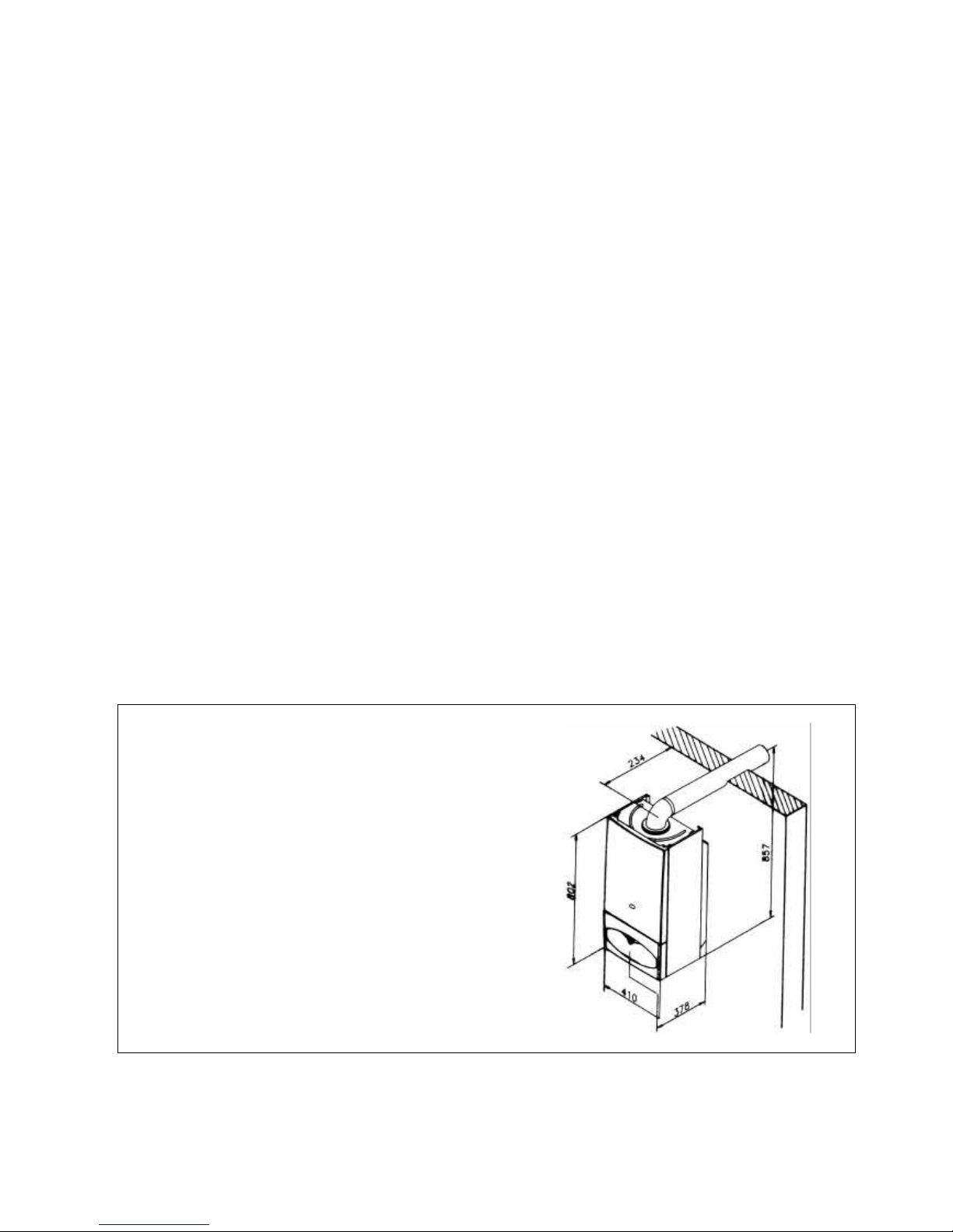
2.1. DIMENSIONS
The Combination boiler is delivered in two separate
packages;
- the boiler itself
- the flue system
Weight: 42 kg
Diagram 1
2. TECHNICAL AND DIMENSIONAL CHARACTERISTICS
1.1.1. Instructions and Regulations
Assembly, Installation, First ignition and maintenance must be carried out by a competent person, i
n
accordance with all-current technical regulations and directives.
1.1.2. C.O.S.H.H.
Materials used in the manufacture of this appliance are non-
hazardous and no special precautions are
required when servicing or maintenance is undertaken.
1.1.3. Related Documents
This appliance must be installed strictly in accordance with these instructions.
? The Gas Safety Regulations (Installations & Use) 1996
? The Building Regulations
? The Local Building Regulations
? The Buildings Standards (Scotland - consolidated) Regulations
? Model Water Bye laws
? British Standards code of practice:
B.S. 7593 1992 Treatment of water in domestic hot water central heating systems
B.S. 5546 1990 Installation of hot water supplies for domestic purposes
B.S. 5540 Part 1 2000 Flues
B.S. 5540 Part 2 1989 Air supply
B.S. 5449 1990 Forced circulation hot water systems
B.S. 6798 1987 Installation of gas fired hot water boilers
B.S. 7671 1992 IEE wiring regulations
B.S. 4814 1990 Specification for expansion vessels
B.S. 5482 1994 Installation of L.P.G
For Northern lreland the current rules in force apply
Page 6
6
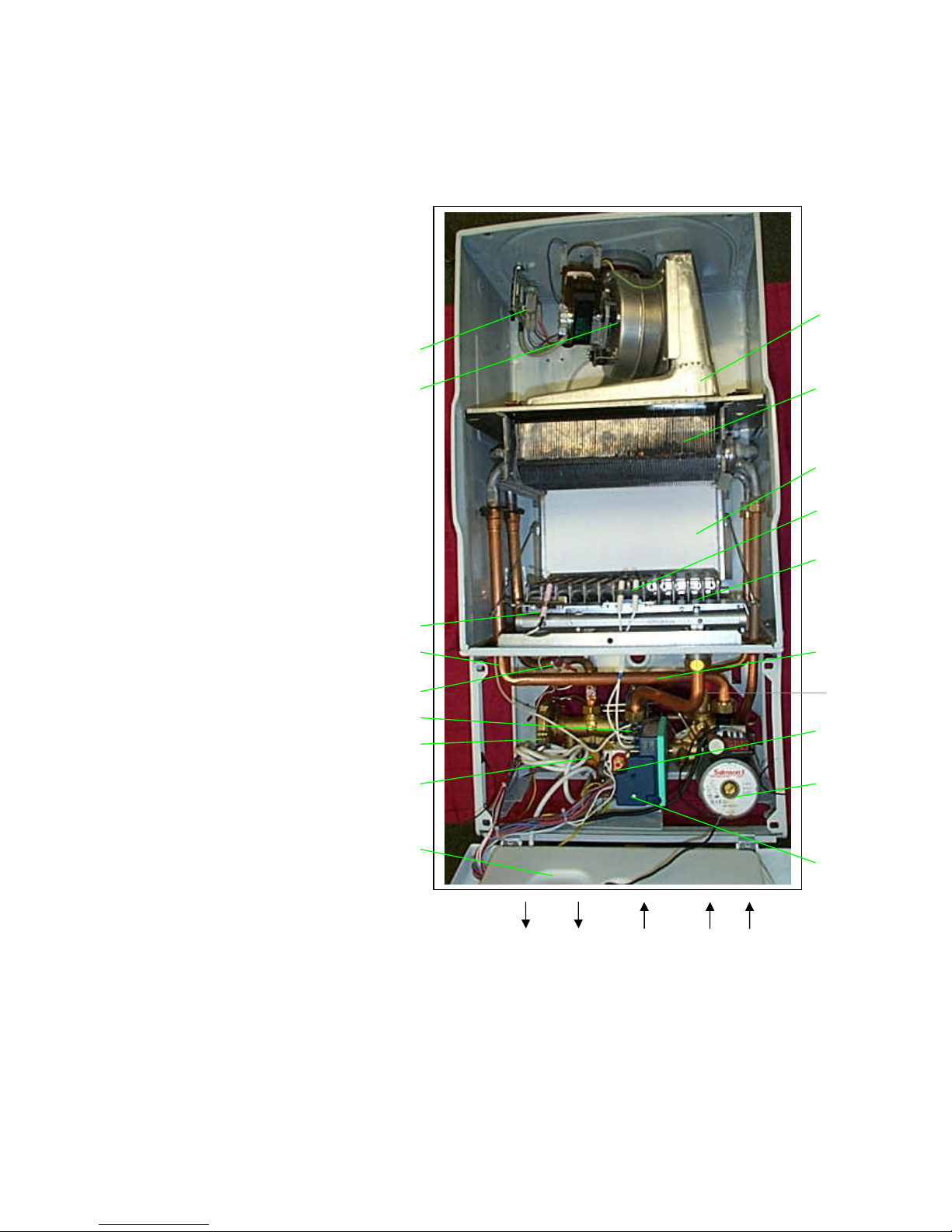
2.2. BOILER SCHEMATIC
1 - Domestic thermistor
2 – Hydroblock
3 - Gas valve
4 - Gas valve ignition module
5 - Fan hood
6 - Burner
7 - Ignition electrodes
8 - Combustion chamber
9 - Integrated heat exchanger
10 - Air pressure switch
11 - Heating safety valve (3 bar)
12 – PCB (in protective case)
13 - Domestic water flow switch
14 – Bypass valve (in hydroblock)
15 - Pump
16 - Expansion vessel (at rear)
17 - Heating thermistor
18 - Overheat safety thermostat
19 - Flame sense electrode
20 - Fan
21 - Loss of water sensor
22 – Automatic air vent (top of exp.
vessel)
A - Heating outlet (3/4” male)
B - Domestic hot water outlet (1/2”
male)
C - Gas (3/4” male)
D - Cold water inlet (1/2” male)
E - Heating return (3/4” male)
Diagram 2
21
19
18
17
20
10
5
15
8
9
6
7
13
11
4
3
12
2
1
A B C D E
Page 7
7
Net calorific value at 15 C and 1013.25 mbar
G20 34.04 MJ/m3
1 mbar approximately equals 10 mm H2O
2.4. TECHNICAL DATA
Heating
Hot water
Heating output adjustable from ... (kW) 8.9 Hot water output
to ... (kW) 23.3 automatically variable from ... (kW) 8.9
from ... (Btu/h) 30368 to ... (kW) 23.3
to ... (Btu/h) 79502 from... (Btu/h) 30368
Efficiency (%) 91 to ... (Btu/h) 79502
Maximum heating temperature (oC) 90 Maximum hot water temperature (oC) 90
Expansion vessel effective capacity (l) 8 Specific flow rate (for 30oC temp rise)
Expansion vessel charge pressure (bar) 0.5 (l/min.) 11.0
Maximum system capacity at 75oC (l) 150 Threshold flow rate (l/min.) 2.3
Safety valve, max. Service pressure (bar) 3 Water flow rate (for 35oC temp rise) (l/min.) 9
Products outlet diameter (mm) 60 Maximum supply pressure (bar) 8
Fresh air inlet diameter (mm) 100 Minimum operating pressure (bar) 0.3
Natural Gas (G20)
? Burner injector (mm)
1,2
Inlet pressure
(mbar)
20
Electrical supply (V) 230 Burner pressure
(mbar)
13
Maximum absorbed power (W) 170 Gas rate maximum (m3/h) 2.88
Level of protection IP44 Gas rate minimum (m3/h) 1.06
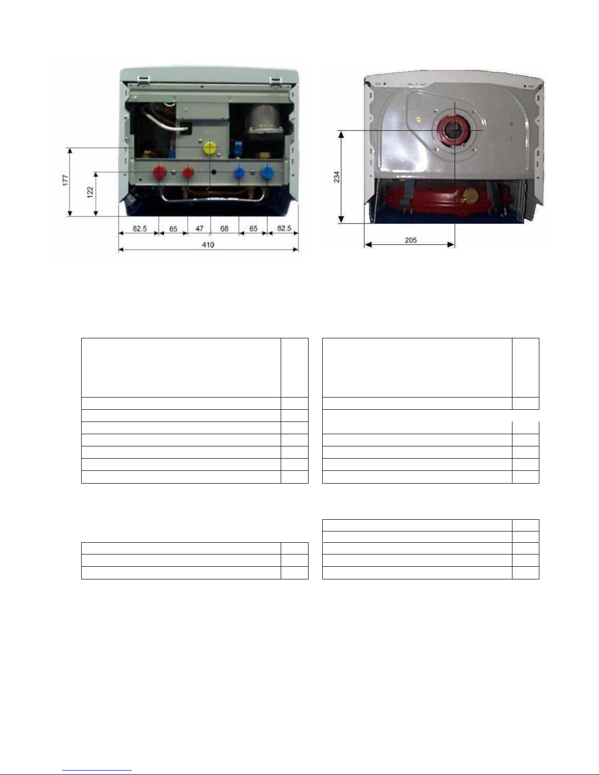
2.3. BOILER CONNECTION DIMENSIONS
Diagram 3
Diagram 4
Page 8

8
2.5. BOILER FLOW DIAGRAMS
air
Combustion products
air
Combustion products
Central heating mode
Diagram 5
Sanitary water mode
Diagram 6
1 - Domestic thermistor
2 – Hydroblock
3 - Gas valve
4 - Gas valve ignition module
5 - Fan hood
6 - Burner
7 - Ignition electrodes
8 - Combustion chamber
9 - Integrated heat exchanger
10 - Air pressure switch
11 - Heating safety valve (3 bar)
12 – PCB (in protective case)
13 - Domestic water flow switch
14 – Bypass valve (in hydroblock)
15 - Pump
16 - Expansion vessel (at rear)
17 - Heating thermistor
18 - Overheat safety thermostat
19 - Flame sense electrode
20 - Fan
21 - Loss of water sensor
22 – Automatic air vent
INLETS / OUTLETS
A - Heating outlet (3/4” male)
B - Domestic hot water outlet (1/2” male)
C - Gas (3/4” male)
D - Cold water inlet (1/2” male)
E - Heating return (3/4” male)
1
A B C D E
2
3
4
5
6
7
8
9
10
11 12 13 15 16 17 18 19 20 21 22
Diagram 7
Page 9

9
2.6. HYDROBLOCK DIAGRAMS
2.6.2.Central Heating Mode
?
When the system is operating in Central Heating Mode, cold water which comes from Central Heating Return pipe is
directed to pump inlet. Water reaches to inlet of primary heat exchanger from outlet of pump. With heat transfer in
primary heat exchanger, hot water is supplied. Hot water that comes from primary heat exchanger is directed to Central
heating outlet.
2.6.3.Domestic Hot Water Mode
Diagram 8
Diagram 9
Diagram 10
Page 10

10
0
1
2
3
4
5
6
0 1000 2000 3000
Water flow (l/h)
Head
(mCE)
2.7. PUMP CHARACTERISTICS
I II III
The factory speed setting of
the pump is III. The pump is
a SALMSON NBL 53/15 O
series.
The pump has 3 different speeds.
According to these speeds pump
performance curve is given at the
diagram on the left.
I : first speed
II : second speed
III : third speed
Diagram 11
?
Switching to Domestic Hot Water System: When a tap is opened, cold water reaches to hydroblock from Cold Water
Inlet. The pressure is sensed by the diaphragm by means of pressure connection pipes (shown as “a”). The diaphragm (b)
moves with the difference in pressures. The pin which is connected to diaphragm moves to right (as shown with arrow
“c”) and operates the domestic water flow switch. This switch gives signals to control card and lets the system control the
domestic hot water system.
? For Domestic Hot Water system (shown as “2”): Cold water which is supplied from Cold Water Inlet reaches to
secondary heat exchanger inlet. The heat is transferred between primary and secondary heat exchangers. (The secondary
heat exchanger is installed inside primary heat exchanger.) The hot water which is supplied from Secondary heat
exchanger outlet is directed to Domestic Hot Water Outlet.
? For Central Heating system (shown as “1”): There is no flow in whole system, the flow is only inside the boiler. Cold
central heating water is pumped to primary heat exchanger. In primary heat exchanger, heat is transferred from primary
heat exchanger to secondary heat exchanger. The water that comes from primary heat exchanger outlet, is directed to
pump inlet by a connection pipe (shown by green arrow).
Page 11

11
2.8. HEATING SYSTEM DESIGN
? The combination boiler is compatible with any type of installation.
? Heating surfaces may consist of radiators, convectors or fan assisted convectors.
?
The combination boiler can be piped directly to an underfloor heating system without the need for a
mixing bottle. The maximum central heating flow temperature can be set to 40
o
C on the boiler printed
circuit board during commissioning.
? Pipe sectio
nal areas shall be determined in accordance with normal practices, using the output/
pressure curve (diagram 11). The distribution system shall be calculated in accordance with the output
requirements of the actual system, not the maximum output of the boi
ler. However, provision shall be
made to ensure sufficient flow so that the temperature difference between the flow and return pipes be
less than or equal to 20oC. The minimum flow is 500 l/h.
? The piping system shall be routed so as to avoid any air pocket
s and facilitate permanent venting of
the installation. Bleed fittings must be provided at every high point of the system and on all radiators.
?
The total volume of water permitted for the heating system depends, amongst other things, on the
static head in
the cold condition. The expansion vessel on the boiler is pressurised at 0,5 bar
(corresponding to a static head of 5 m w.g.) and allows a maximum system volume of 150 litres for an
average temperature of 75oC and a maximum service pressure of 3 bar. An ad
ditional expansion vessel
can be fitted to the system if required, see diagram 12.
? Provision shall be made for a drain valve at the lowest point of the system.
? Where thermostatic radiator valves are fitted, not all radiators must be fitted with this type o
f valve,
and in particular, where the room thermostat is installed.
? In the case of an existing installation, it is ESSENTIAL
that the system is thoroughly flushed prior
to installing the new boiler.
Filling the system
The system is filled by using a filling device.
2.9. DOMESTIC HOT WATER SYSTEM DESIGN
?
Copper tubing may be used for the domestic hot water system. Unnecessary pressure losses should
be avoided.
?
The boiler will operate with a minimum supply pressure of 0,3 bar, but under reduced flow rate.
Best operating comfort will be obtained from a supply pressure of 1 bar.
'Hard Water Areas'
In areas where the water is 'hard', more than 200mg/litre, it is recommended that a proprietary scale
reducer is fitted in the cold water supply to the boiler.
Sheet metal parts
WARNING: Wh
en installing or servicing this boiler, care should be taken when handling the edges of
sheet metal parts to avoid the possibility of personal injury.
Installing the boiler
Prior to starting work, the system must be thoroughly flushed using a propriety cle
anser such as
Sentinel X300
to eliminate any foreign matter and contamination e.g. metal filings, solder particles,
oil, grease etc.
Note. Solvent products could cause damage to the system.
? Engage boiler upper part onto the hanging bracket.
Fit the washers between the boiler pipes and the inlet and outlet fittings and connect the boiler.
Page 12

12
3.1. PIPING SYSTEM INSTALLATION
? Heating system connections - Pipe diam. 22 mm
? Hot water system connections - Pipe diam.15mm
? Gas connection - Pipe diam. 22mm
? Heating safety valve connection - Pipe diam. 15mm
3.1.1. Water connection
Connect the
system pipework to the boiler observing the correct flow and return format as shown
in diagram 12.
3.1.2. Safety valve discharge
The heating safety valve outlet pipe should be extended horizontally to the outside wall.
WARNING: It must not discharge above
an entrance or window or any type of public access
area.
Connect the safety valve discharge pipe to the outlet of the heating safety valve, the discharge
must be extended using not less than 13 mm o.d. pipe, to discharge in a visible position outside
the building, facing downward preferably over a drain.
The pipe must have a continuous fall and be routed to a position so that any discharge of water,
possibly boiling or steam, cannot create any danger to persons, damage to property or external
electrical components and wiring. Tighten all pipe connection joints.
3.1.3. Gas connection
?
The supply from the governed gas meter must be of adequate size to provide a constant inlet
working pressure which is convenient of gas supplied.
To avoid low gas pressure prob
lems, it is recommended that the gas supply is connected using 18
mm pipe.
?
On completion, the gas installation must be tested using the pressure drop method and purged
in accordance with the current issue of BS6891.
3.1.4. Gas Safety (Installation and use) Regulations
In your interests and that of gas safety, it is the law that ALL gas appliances are installed and
serviced by a competent person in accordance with the above regulations.
Flow
control
valve
Bypass
valve
Filling
device
Cold water
supply
Domestic h ot water
Heating outlet
Flow
control
valv
e
Boiler
Flow
control
valve
Heating return
Additional
expansion
vessel (if
required)
3. INSTALLATION
Diagram 12
Page 13

13
3.2. BOILER LOCATION
3.2.1. Clearances
The boiler must be at least 1 m. far away from flammable materials. Heat sensitive walls must be
protected by suitable insulation.
The position of the boiler must be such that there is adequate spac
e for servicing. The recommended
clearances are:
50 mm, either side of the boiler,
600 mm at the front of the boiler,
300 mm below the boiler,
200 mm top of the boiler.
? Place template on wall in required position, making allowances for the necessary clearances etc.
Note:
It is permissible to install the boiler with smaller clearances than those quoted above
PROVIDING that adequate consideration is given for Servicing/ Repairs at a later date. If any doubt
exists, contact the Service Company.
? Mark the position of the holes for the hanging bracket.
? Drill, plug and fix the hanging bracket to the wall using suitable screws.
? Check that the hanging bracket is level.
? For horizontal flue system, mark the position for the flue hole as follows:
3.2.2. Flue to rear of boiler
? Mark correct position of hole from template.
3.2.3. Flue to side of boiler
?
Mark the horizontal centre line for the hole on the rear wall. Extend the horizontal centre line to the
side wall and mark the vertical centre line of flue hole.
3.2.4. Cutting the flue hole
?
Making allowance for the slope of the flue, cut hole in external wall, preferably using a core drill.
For installations with internal and external access use a 105 mm diameter core drill.
For installations with internal access only use a 125 mm diameter core drill.
Important
When cutting the flue hole and when extending the flue centre line to a side wall, remember that the
flue system must have a fall of about 35 mm per metre of flue DOWNWARD towards the terminal.
There must NEVER be a downward incline towards the boiler.
3.2.5. Terminal position
The minimum acceptable spacings from the terminal to obstructions and ventilation openings are
shown in diagram 12.
The boiler must be installed so that the terminal is exposed to the external air.
Should any doubt exist as to the permissible position of the terminal, contact the Service Company.
3.2.5.1. Terminal guard
If a terminal guard is required,
a suitably approved terminal guard should be fitted (in accordance with
B.S.5440 Part 1), where the flue terminates less than 2m from the outside floor.
3.2.6. Cupboard or compartment ventilation
The boiler can be fitted in a cupboard or compartment without the need for permanent ventilation.
A
-
Under a window …………………………….. 300
B - Under an air vent ……………………………. 300
C - Under a gutter ………………………………... 75
D - Under a balcony …………………………….. 300
E - From an adjacent window ………………….. 300
F - From an adjacent air vent …………………... 300
G - From vertical or horizontal air pipes ………. 300
H - From an external corner of the building …… 300
I - From an internal corner of the building ……. 300
L - From the ground or from another floor …….. 300
M - Between two terminals vertically …………..1500
N - Between two terminals horizontally ……...… 600
Diagram 12
Page 14

14
3.3. BOILER INSTALLATION
3.3.1. Statutory requirements
The installation of this boiler must be carried out by a competent person in accordance with the
relevant requirements of the current issue of;
The Gas Safety (Installation and Use) Regulations
The Building Regulations
The local water company Byelaws
The Health and Safety at Work Act
3.3.2. Sheet metal parts
WARNING: When installing or servicing this boiler, care should be taken when handling the edges
of sheet metal parts to avoid the possibility of personal injury.
3.3.3. Installing the boiler
Prior to starting work, the system must be thoroughly flushed using a propriety cleanser such as
Sentinel X300
to eliminate any foreign matter and contamination e.g. metal filings, solder particles,
oil, grease etc.
Note. Solvent products could cause damage to the system.
? Engage boiler upper part onto the hanging bracket.
Fit the washers between the boiler pipes and the inlet and outlet fittings and connect the boiler.
3.4. FLUE INSTALLATION
Top outlet flue - kit 85089
The boiler is only suitable for top outlet flue connection.
Calculation of flue cutting lengths
? Measure wall thickness e (mm), see diagram 13.
?
For side flues, measure distance from inside face of side wall to
centre line of boiler and subtract 210 to get dimension a (mm).
?
Refer to table 2 for cutting lengths of both inner and outer flue
pipes for each of the various flue options available.
Important:
All flue cutting lengths must be measured from the
terminal end of the flue pipes, see diagram 14. When th
e dimension
X
measured on site is greater than that given in table 2, a flue
extension kit will be required, refer to table 3 for details.
3.4.1. Extended flue
The horizontal flue is extended by using one or more of the 1000
mm extension pipes, available from Mikrofill. These
are connected together by push fit type joints, clamps and seals.
3.4.1.1. Calculation of flue cutting lengths for extended flue
? Using the correct number of extension kits as table 3,
measure dimensions a and e, see diagram 15. Cut both the inner
and outer pipes to the dimensions given in table 4.
Important: All cutting lengths should be measured from the
push fit joint end of the extension pipe, Do not leave any burrs
or sharp edges on the cut ends of the pipes.
Table 2
Flue cutting lengths
Flue Cutting length (mm) Comments
option Outer pipe Inner pipe
Rear flue e+160 e+244 max. wall thickness
‘e’ without ext. 756mm
Side flue e+a+145 e+a+229 max. distance
(left or right) ‘x’ without ext. 990mm
Table 3
Number of extension kits required
Flue option
Dimension 'X'
No.of
extension kits
Side flue
(left or right)
991
to 1991 mm
1
Note: Maximum flue length is 3 meters.
(No curves)
Diagram 13
Diagram 14
Page 15

15
Table 4
Flue cutting lengths
Flue option Cutting length (mm) Comments
Outer pipe Inner pipe
e+a-755 e+a-755 Side flue
(left or right)
max. dimension
‘x’ without ext.
990mm
Installation of flue assembly
? Fit rubber sealing collar (A), see diagram 16, into
groove at the outer end of pipe (B).
? Fit outer pipe (B) into wall with groove to the outside.
? Pull pipe inwards to bring rubber sealing collar hard up
against external wall, see diagram 16.
? Fit internal plastic flange (C) onto outer pipe. Push
along the pipe until engaged against internal wall.
? From inside, insert inner pipe (D) into outer pipe.
? Fit both ‘O’ rings (E) into the flue elbow (F) , one at
the inlet, one at the outlet. By necessity, they are a loose fit,
apply a small amount of silicone grease to each 'O' ring
when fitting.
? Slacken the two screws and fit the clamp and seal
(G) onto the elbow.
? Take hold of the inner flue and push gently onto
the elbow outlet taking care not to tear the ‘O’ ring.
Important: If the flue has been cut, ensure that there are
no burrs that could damage the ‘O’ ring.
? Push the elbow clamp and seal over the outer flue.
? Remove the backing from the self adhesive gas-
ket (H) and carefully fit gasket to base of flue elbow.
? Fit elbow onto boiler and secure with the
four screws (I).
3.4.2. Concentric flue system
The maximum permissible length (L) for the concentric flue system is 2 m.
For each 90o flue elbow used, (or two 45o elbows) the maximum permissible length (L)
must
be reduced by 1 meter.
The standard flue kit , see diag.11, comprises
:
- External rubber sealing collar ………… A
- Outer pipe …………………………….. B
- Plastic flange …………………………. C
- Inner pipe ………………………………D
- 2 'O' rings …………………………….. E
- Elbow …………………………………. F
- Clamp and seal ………………………...G
- Gasket ………………………………… H
- Four screws …………………………… I
Diagram 15
A B C D E
F
G H I
Diagram 16
Page 16

16
3.5. ELECTRICAL CONNECTION
Warning.
This boiler must be earthed. The phase and the neutral line connections of power cable must
be correct.
All system components must be of an approved type.
Connection of the whole elect
rical system and any heating system controls to the electrical supply must
be through a common isolator.
Isolation should preferably be by a double pole switched fused spur box having a minimum contact
separation of 3 mm on each pole. The fused spur box sh
ould be readily accessible and preferably
adjacent to the boiler. It should be identified as to its use.
A fused three pin plug and shuttered socket outlet may be used instead of a fused spur box provided that;
a) They are not used in a room containing a fixed bath or shower.
b) Both the plug and socket comply with the current issue of BS1363.
The mains electrical supply must be maintained at all times in order to provide domestic hot water. Do
not interrupt the mains supply with a time switch or programmer.
WARNING: ON NO ACCOUNT MUST ANY EXTERNAL VOLTAGE BE APPLIED TO ANY OF
THE TERMINALS ON THE HEATING CONTROLS CONNECTION PLUG.
Warning:
This appliance must be wired in accordance with these instructions. Any fault arising from
incorrect wiring cannot be put right under the terms of the Mikrofill guarantee.
3.5.1. External controls
The combination boiler is designed to operate at maximum efficiency at all times, but will be most
efficient and economical when connected to a room thermostat.
A suitable room thermostat is available as an accessory.
The boiler will work for heating without a room thermostat being connected provided that the wire link
fitted between the two terminals of the connector (A) is left in place, see diagram 18.
Warning : Maximum Clock (Timer) load is 12 Vdc, 10 mA
ON NO ACCOUNT
must any electrical voltage be applied to any of the terminals of the external
controls plug.
Note: For further information, see the building regulations 1991- Conservation of Fuel and Power
-1995 edition - appendix G, Table 4b.
Diagram 17
Diagram 18
Diagram 19
Page 17

17
4.1. Filling
When cold, system pressure should be about 1 bar. If while running venting off of air dissolved in
the water causes the pressure of the central heating system to drop below the minimum level
described above, the user must utilise a filling loop to bring it back to the original value. During
operation, water pressure in the boiler when hot should be about 1 -
2 bars. After filling, always
close and disconnect the filling loop.
Note -
If there is a possibility of air pockets forming in certain points of the central heating
system flow and return pipes, you are recommended to fit an air vent valve at these points.
4.2. Gas connection
Gas connection should be carried out using a rigid pipe.
The flow at the gas meter should be sufficient for the simultaneous use of all appliances
connected to it. Connect the gas supply to the boiler according to current regu
lations. The
diameter of the gas tube leaving the boiler is not the determining factor in choosing the diameter
of the pipe between the appliance and the meter. This must be selected in relation to length and
pressure drop and in any instance should not be less than 22mm.
The whole of the gas installation including the meter should be inspected and tested for soundness
and purged in accordance with B56891-1988.
N.B. - The filling loop will be fitted by the installer in accordance with water by laws, at the
time
of installing the system. It is NOT a part of the boiler.
4. COMMISSIONING
Page 18

18
COMMISSIONING
The c
ommissioning and first firing of the boiler must only be done
by a competent person.
Gas installation
It is recommended that any air is purged from the supply at the gas
inlet test point on the gas valve, see diagram 20.
Filling the system
Diagram 20
Undo the cap of automatic air vent on the
expansion vessel open and leave it open.
Open the boiler isolating valves. (Slot of the screw
corresponds to flow direction) Fill the system by
using a filling
device.
Remove the air in pump by opening
the screw front of the pump. (After
removing air close the screw.)
Diagram 21
Diagram 22
Diagram 23
Page 19

19
COMMISSIONING
Leave the cap of automatic air
vent on the expansion ve
ssel
open.
Open various hot water taps
to bleed system.
Make sure the pressure gauge on control panel indicates a system pressure of 1 and 2 bar. Refill the
system as necessary.
Bleed each radiator to remove the
air,
re-tighten bleed screws
Diagram 24
Diagram 25
Diagram 26
Diagram 27
Page 20

20
COMMISSIONING
4.3. Lighting the boiler
Make sure that:
? The boiler is connected to the electrical supply.
? The gas service cock is open.
Then follow the instructions below :
Turn on the mode selector knob
The pressure must be between 1 and 2 bar. If not, the system must be filled by a competent person.
?
Adjust heating temperature to maximum.
?
Check that any external controls, if fitted, are calling
for heat (set room thermostat to maximum).
? Allow th
e temperature to rise to the maximum value,
with all radiator valves open. The temperature rise will
cause release of the gases contained in the water of the
central heating system.
?
Gases driven towards the boiler will be automatically
released through the automatic air vent.
?
The gases trapped at the highest point of the system
must be released by bleeding the radiators. On reaching
maximum temperature, the boiler should be turned off and
the system drained as rapidly as possible whilst still hot.
? Refill
system to a pressure of between 1 and 2 bar and
vent as before.
Restart boiler and operate until a maximum temperature is
reached. Shut down boiler and vent heating system. If
necessary, top up heating system and make sure that a
pressure of 1 bar is indicated when system is COLD.
?
?
To stop boiler turn the selector knob
off.
4.4. On board adjustments: potentiometers and trimmers.
MAX RISC: maximum heating mode trimmer, 0 -100 %.
0 % corresponds to the minimum value mechanically set on the MFC: 30 mA with NG, 50 mA with LPG.
RLA: step opening level trimmer, 0 -100 %.
When the MAX RISC trimmer is put to the very minimum, the step opening duration is forced to 20 s. in order
to help the setting operation. The 3 minute delay is cancelled. Factory setting is 100%. Do not change its setting.
4.5. On board adjustments: jumpers.
JP l: DO NOT TOUCH this jumper.
JP 2: when fit in, the pump is not powered when working in Heating mode. This f
eature addresses to systems
with external pumps.
JP 3: when fit in, the heating temperature range changes to 30 – 40 oC, for underfloor systems.
JP 4: when fit in, the three minute delay on restarting after a cut-out due to the primary water temperature se
t
being exceeded, is excluded.
Diagram 28
Diagram 29
Diagram 30
Page 21

21
4.6. Setting the maximum heating temperature
The maximum heating temperature can be preset at
commissioning stage to suit the type of heating system.
For example, for use with underfloor heating, the maximum
heating temperature can be set to 40
o
C. To adjust the maximum
temperature, proceed as follows:
?
Remove the jumper cap from the rear of the control panel
to gain access to jumper JP3 (see diagram 31).
Note: To adjust the maximum heating temperature it is only
necessary to fit JP3. DO NOT touch any other jumpers.
? Refit the jumper cap.
JP 3 is fitted ? 40oC. Maximum.
JP 3 is not fitted ? 90oC. Maximum.
Factory setting 90oC. Maximum.
Diagram 31
JP4
JP3
JP2
JP1
MAX RIS
RLA
Diagram 32
MAX RIS
?- kW +?
4.7. Setting the heating output
The heating output can be set with the use of the trimmer
potentiometer; proceed as follows:
Open the lower front panel. Then remove the jumpers cover
behind the PCB card box cover. Adjust the maximum heat
desired from MAX RISC potentiometer.
?
?
Adjust the heating output by turning the potentiometer
clockwise to increase, anti-clockwise to decrease.
? Refit the jumper cap and close the lower control panel.
Note:
Adjustment of the heating output does not affect the
domestic hot water output.
Table 1
Burner Pressure Nominal Output
1.2 mbar 8,9 kW 30400 Btu/h
3.7 mbar 12.98 kW 40980 Btu/h
6.9 mbar 13.75 kW 44400 Btu/h
12.1 mbar 23.2 kW 78530 Btu/h
12.3 mbar 23.3 kW 79555 Btu/h
Page 22

22
??
Rotate the domestic hot water adjustment knob left or
right to adjust the maximum temperature of the
sanitary water (35oC to 65
o
C). For increasing rotate
the knob in clockwise and for decreasing rotate in
anti-clockwise.
Rotate the central heating adjustment knob left or
right to adjust the maximum temperature of the
heating (30oC to 85
o
C). For increasing rotate the
knob in clockwise and for decreasing rotate in anti-
clockwise.
??
4.8. Safety Devices
The combination boiler incorporates a visual l
ed display that indicates fault conditions, should they occur.
In the event of a fault, the display will indicate, by means of leds, exactly in which area the fault lies.
Should the boiler fail to operate during Commissioning, the most likely fault is that
the gas supply to the
boiler has not been turned on or purged sufficiently or that there is no pressure in the heating system. These
are indicated as follows :
No gas supply
?
This will be indicated by illuminating light of the
reset button
To rectify this, proceed as follows:
? Rectify the gas supply problem.
?
Restart the boiler by turning the selector knob and
then press the reset button.
Insufficient system pressure
This will be indicated on the led display as blinking
warning led 3. pressure is low.
To rectify this the system must be re-fill
ed, refer to
`Commissioning'.
Other faults
These are indicated on the led display by a blinking led.
Further information on the fault codes can be found in
the 'Servicing Instructions'.
General safety devices
Air flow rate safety device
If an obstruction, even partial, of the flue occurs, for
any reason whatsoever, the built in safety system of the
boiler will turn the boiler OFF and the fan will continue
to run.
The boiler will be r
eady to operate when the fault has
been cleared.
Overheat safety
In case of boiler overheating, the overheat thermostat
will turn the boiler off. The thermostat, located on the
heat exchanger outlet pipe, will need to be manually
reset.
In case of power supply failure
The boiler no longer operates.
As soon as power supply is restored, the boiler will be
automatically restarted.
Frost protection
The combination boiler
has a built in frost protection
device that protects the boiler from freezing. If the
boiler is to be left and there is a risk of frost, ensure that
the gas and electrical supplies are left connected. The
frost protection device will light the boiler when the
temperature of the boiler water falls below 5
o
C When
the temperature reaches 30oC, the boiler stops.
Note :
This device works irrespective of any room
thermostat setting and will protect only the boiler.
Diagram 33
Diagram 34
Page 23

23
5. SETTINGS
Gas valve setting
All boilers are tested and factory set during manufacture.
Should it be necessary to reset a gas valve, for example,
after replacement, proceed as follows:
? Shut down boiler.
Minimum setting (See values on table A)
?
Remove electrical connectors from the modulating
gas valve coil, see diagram 35.
?
Connect a suitable pressure gauge to the pressure
outlet on valve, see diagram 36.
? T
urn the OFF/Summer/Winter switch to the ‘Winter’
position.
?
Turn the central heating temperature adjuster to
maximum setting.
?
Remove the protective cover from the gas valve
adjuster.
?
Connect the gas valve adjustment tool to adjustment
nut and screw, see diagram 37.
? Turn inner part, see diagram 38:
CLOCKWISE: To increase the pressure.
ANTICLOCKWISE: To decrease the pressure.
After adjustment, connect electrical connector, protective
cover.
Maximum setting (See values on table A)
? Remove the protective cover f
rom the gas valve
adjuster.
? Push the grey rod on tool.
? Turn outer part, see diagram 39:
CLOCKWISE: To increase the pressure.
ANTICLOCKWISE: To decrease the pressure. After
adjustment, refit the cover to the gas valve adjuster.
By-pass
The combination boiler has a built-in automatic bypass.
Gas
Gas inlet
pressure
Burner pressure
Diam. of injector
nozzle
(mbar) Min. Max. mm.
NG (G20) 20 1.2 12.3 1.2
Gas pressure adjustment values
Diagram 36
Diagram 37
Diagram 38
Diagram 35
Diagram 39
Table 5
 Loading...