

Page 1

CON D ENSING BOILERS
INSP I R E D E FFI C IENC Y
ETHOS 70, 90, 110 & 130 WALL MOUNTED CONDENSING BOILERS
TECHNICAL DOCUMENTATION
ISSUE 03/16 Rev. 03
Page 2

Page 3

TABLE OF CONTENTS
TECHNICAL DOCUMENTATION 03
Technical Data
Dimensions
Safety Guidelines
Conditions
General Guidelines
Service
General Restrictions
Description
General
Working Principle and Design
Application Features
Main Components
Bottom Connections
Boiler Control
Safety Aspects
Delivery & Transport
Delivery
Transport
Moving
Access Requirements
Installation
Regulations
Installation Area
Mounting - Solid Walls
Mounting - Non-Load Bearing Walls
Installation Guidelines
Ventilation
Gas Connection
Water Connections
Electrical Connections
Internal Controls Breakdown (Main PCB)
Internal Controls Breakdown (Control Fascia)
External Controls Breakdown (Din Rail)
Flue Connection
Flue Gas Outlet and Air Inlet Pipe
Flue Adaptor Installation
Flue Gas Data
Flue Length
Calculation of Diameter and Length
Resistance Table
Condense Connections
Safety Valve Connection
Hydraulic System
Pump Characteristics
Shut-Off Valves
Valves (Boilers in Cascade Arrangement)
Water Flow Protection Device
Water Pressure
System Expansion Vessel
Water Pressure Protection Device
Water Temperature
Water Quality
Water Hardness
1.
2.
3.
4.
5.
6.
04
05
06
07
07
08
09
10
11
12
13
14
15
16
17
18
19
20
21
22
Operating Instructions
Operation
Controls
Boiler Module
PCB Symbol Key
Switching On the Appliance
Switching Off the Appliance
Information Display
DHW Operation
Heating Operation
Displaying Information
Table Parameter List
History Mode
Possible Error Codes
Possible Error Codes continued.
Commissioning
General
Reference Value for Maximum Load
Reference Value for Minimum Load
Maximum Load Adjustment
Minimum Load Adjustment
Setting the CO
2
Value for the ETHOS Range
Conversion from Natural Gas to Propane
Cascade Set-Up
Auto Detection Mode
Cascade Test Mode
Maintenance
Safety
Servicing Schedule
Gas Valve and Venturi
Fan and Burner Assembly (ETHOS 70)
Fan and Burner Assembly (ETHOS 90, 110 and 130)
Pump / Pump Head
Setting / Checking of Electrode and Probe Gaps
Component List
Casing and Electrical Components
Core Components (ETHOS 70)
Core Components (ETHOS 90, 110 and 130)
Conversion Formulae & Factors
Notes
7.
8.
9.
10.
11.
12.
13.
22
23
24
25
26
27
28
29
30
31
31
32
33
34
35
36
37
38
39
40
41
42
44
Page 4
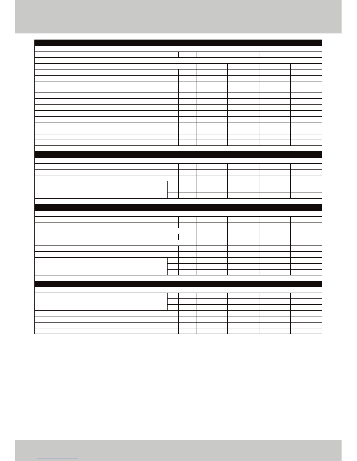
TECHNICAL DATA
04 TECHNICAL DOCUMENTATION
ETHOS 130
12.4
116
1¼”
¾”
100
100
110/150
420
230
50
6
6200
950
13.0 - 130.0
12.8 - 127.7
14.0 - 140.4
13.6
15.8
5.3
52
75
T 120
200
3.0 - 5.5
90
0.5 - 6.0
17 - 20
17 - 20
30 - 50
8.4
8.4
9.5
33.0
98.2
108.0
95.63
ETHOS 110
10.7
102
1¼”
¾”
100
100
110/150
370
230
50
6
6750
900
11.0 - 110.0
10.7 - 106.9
11.9 - 118.8
11.5
13.4
4.5
52
75
T 120
200
3.0 - 5.5
90
0.5 - 6.0
17 - 20
17 - 20
30 - 50
8.4
8.4
9.5
33.0
97.2
108.0
95.46
ETHOS 90
8.8
91
1¼”
¾”
100
100
110/150
370
230
50
6
6200
900
9.0 - 90.0
8.8 - 87.5
9.7 - 97.2
9.4
10.9
3.7
52
75
T 120
140
3.0 - 5.5
90
0.5 - 6.0
17 - 20
17 - 20
30 - 50
8.4
8.4
9.5
33.0
97.2
108.0
95.46
ETHOS 70
7.0
67
¾”
¾”
80
80
80/125
370
230
50
6
6600
1000
7.0 - 70.0
6.8 - 68.4
7.7 - 76.8
7.4
8.6
2.9
52
75
T 120
140
3.0 - 5.5
90
0.5 - 4.0
17 - 20
17 - 20
30 - 50
8.4
8.4
9.5
33.0
97.7
109.7
96.79
905 x 530 x 475 905 x 530 x 675
With this resistance value the heat output will remain within the specifications indicated on the dataplate; if the resistance is higher, the
heat output will be reduced.
GENERAL
Dimensions (Height x Width x Depth)
Model
Water Content of Appliance
Weight (Empty)
Flow / Return Connections
Gas Connection
Flue Connection
Air Supply Connection
Concentric (Optional)
Power Consumption
Electrical Supply
Frequency
Fuse Protection
Maximum Fan Speed
Minimum Fan Speed
HEATING PERFORMANCE
Nominal Heat Input (Nett)
Nominal Heat Output at 80/60°C
Nominal Heat Output at 50/30°C
Maximum Gas Consumption
TECHNICAL DATA
Flue Gas Dew Point
Flue Temperature at 80/60°C
(at ambient temperature of 20°C)
Flue Material Temperature Class
Permitted Maximum Resistance of Flue System*
Condensation pH Value
Maximum CH Flow Temperature
CH Water Pressure (Minimum / Maximum)
Minimum / Maximum Gas Pressure
ENVIRONMENTAL DATA
Flue Gas CO
2
Content
NO
X
Levels
Maximum Efficiency (Nett Non-Condensing)
Maximum Efficiency (Nett Condensing)
Seasonal Efficiency
*
mm
litre
kg
BSP
BSP
mm
mm
mm
W
V
Hz
A
RPM
RPM
kW
kW
kW
m
3
/hr
m
3
/hr
m
3
/hr
°C
°C
Pa
°C
bar
mbar
mbar
mbar
%
%
%
mg/kW
%
%
%
G20
G25
G31
G20
G25
G31
G20
G25
G31
Page 5
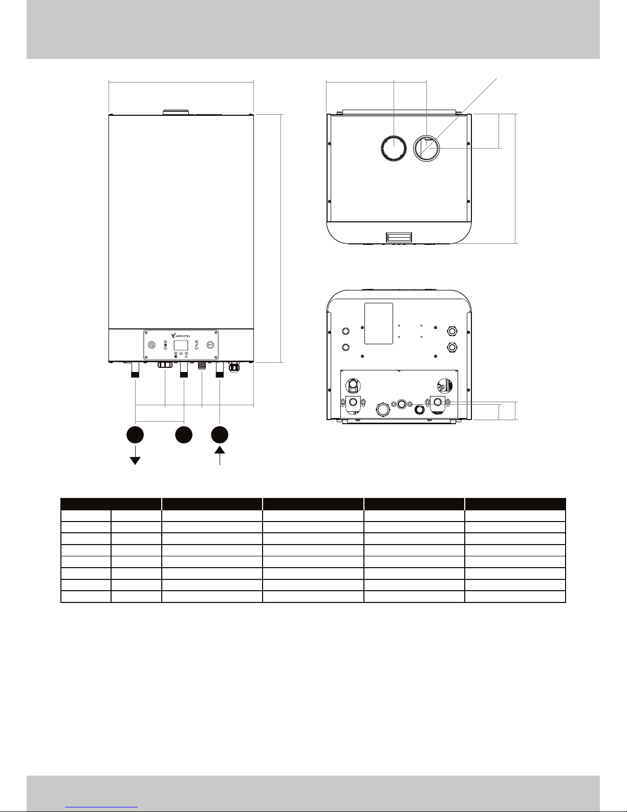
DIMENSIONS
TECHNICAL DOCUMENTATION 05
▲ FIGURE 01. DIMENSIONS OF THE ETHOS WALL MOUNTED BOILERS.
• All dimensions are in millimetres unless otherwise specified.
• Data may deviate slightly due to fabrication tolerances.
• We reserve the right to make changes without prior notification.
530
905
110
70
180
65 E F
GG H
245
A
C
D
Ø B
55
75
ETHOS 130
140
100
95
675
75
115
1¼”
¾”
ETHOS 110
140
100
95
675
75
115
1¼”
¾”
ETHOS 90
140
100
95
475
65
125
1¼”
¾”
ETHOS 70
120
80
125
475
65
125
¾”
¾”
mm
mm
mm
mm
mm
mm
in
in
A
B
C
D
E
F
G
H
Page 6

SAFETY GUIDELINES
06 TECHNICAL DOCUMENTATION
CONDITIONS
Mikrofill Systems Ltd. shall not be liable for any damages caused by non-compliance with this manuals
instructions. Only original parts must be used for service purposes.
GENERAL GUIDELINES
The appliance is not intended for use by persons (including children) with reduced mental, physical or sensory
capabilities, or lack of experience or knowledge, unless they have been given supervision or instruction
concerning the use of the appliance by a person responsible for their safety.
It is a statutory requirement that all gas appliances are installed in accordance with the manufacturers
instructions and all regulations in force. All instructions should be fully read before installing or using the
appliance. All installations should be carried out by competent persons as described in the Gas Safety
(Installation and Use) Regulations i.e. Gas Safe registered and holding current certification.
The manufacturers instructions MUST NOT be taken in any way as overriding statutory obligations.
This boiler has been tested and certified to comply with all necessary European directives, latest building
regulations and efficiency requirements, is CE marked and complies with;
• 2009/142/EC Gas Appliance Directive.
• 2014/35/EU Low Voltage Directive.
• 2014/30/EU Electromagnetic Compatibility Directive.
This boiler should be installed in compliance with;
• Building Regulations.
• Building Regulations (Scotland-Consolidated).
• Building Regulations (Northern Ireland).
• The Health and Safety at Work Act.
• Gas Safety (Installation and Use) Regulations.
• Water Fittings Regulations or Water By-laws in Scotland.
• Local Water Company By-laws
The boiler should not be modified in any way. Any modifications will invalidate the gas approval and
invalidate the warranty.
ATTENTION: HIGH VOLTAGE!
Before opening the boiler casing for maintenance or servicing, the 230 VAC main supply
to the boiler must be disconnected!
Page 7
SAFETY GUIDELINES
TECHNICAL DOCUMENTATION 07
DESCRIPTION
SERVICE
Should you require any assistance during installation or in the unlikely event of a product failure please do not
hesitate to contact our technical department on 03452 60 60 20.
GENERAL RESTRICTIONS
Mikrofill products should always be used, installed and maintained in accordance with the statutory
requirements, specifications and standards applicable to these installations. Mikrofill cannot be held
responsible for any losses or damage whether direct or consequential that have arisen as a result of incorrect
or poor installation.
GENERAL
The Mikrofill ETHOS wall mounted boilers are environmentally friendly gas fired heating boilers with a
modulation range between approximately 10% and 100% of their maximum output. The appliances have low
NOX and CO emission, which satisfies the most stringent environmental requirements.
The boilers may be used on both open (type B23) as well as room sealed (type C13, C33, C43, C53, C63 or
C83) systems.
The boiler is delivered fully wired, fully assembled, tested and preset complete with emissions report.
WORKING PRINCIPLE AND DESIGN
Air is drawn in as required, via a variable speed fan. The gas valve measures the negative pressure (draught)
in the venturi and modulates the gas valve in response. The gas and air is then thoroughly mixed in the correct
ratio in the fan housing and fired directly into the burner.
The boiler management system compares the actual water flow temperature to the required water
temperature. The management system computes the load required and adjusts the fan speed. This is a
continual process during operation.
The heat transfer takes place in a stainless steel double heat exchanger block. The burner fires into the primary
heat exchanger whilst the second heat exchanger (condenser) is connected downstream in such a manner
that the condense water cannot enter the primary heat exchanger, both heat exchangers consist of several
smooth pipes in the form of a coil and are connected using stainless steel water distribution manifolds.
WARNING!
Particular attention must be given to the safety guidelines as non-compliance will render
the warranty void and may constitute an illegal installation.
The ETHOS range has received CE approval for all relevant European countries and has
been registered under the Product Identification Number 86CN59.
Page 8

DESCRIPTION
08 TECHNICAL DOCUMENTATION
The design of the boiler incorporates the following:
• Full Operation and Fault Diagnostics via LCD.
• Control / High Limit Sensors.
• Integral Boiler Shunt Pump.
• Integral Safety Relief.
• Integral Weather Compensation (Optional External Sensor Required).
• Frost Protection.
• Pressure Read Out.
• Compatible with most External BMS Options.
Page 9
DESCRIPTION
TECHNICAL DOCUMENTATION 09
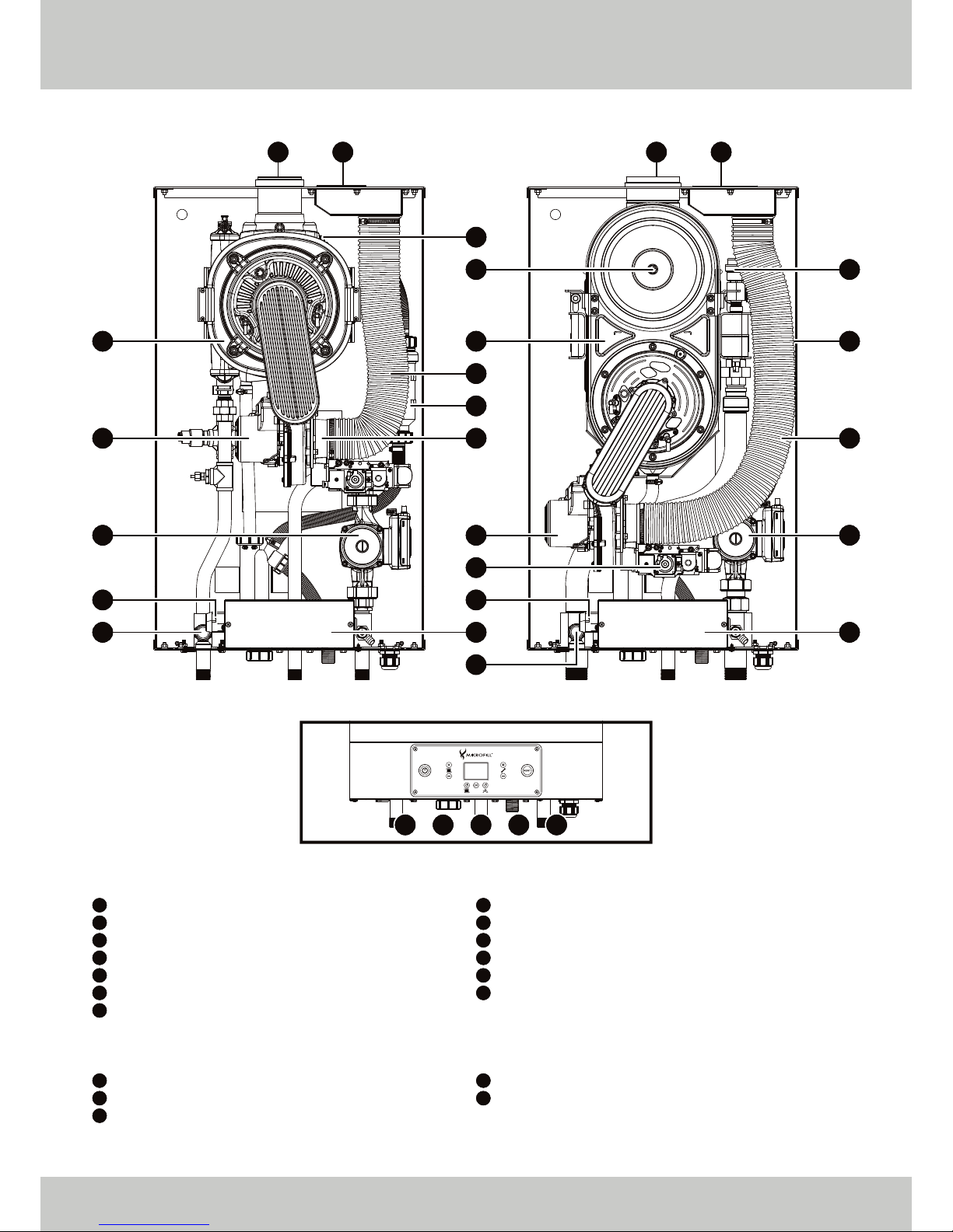
MAIN COMPONENTS:
BOTTOM CONNECTIONS:
* Only present on ETHOS 90, 110 and 130 Heat Exchangers.
ETHOS 70: ETHOS 90, 110 AND 130:
BOTTOM CONNECTIONS:
15 1714 16 18
Air Inlet Connection
Air Inlet Tube
Air Vent Valve*
Combustion Fan
Controls Housing
Flue Gas Temperature Sensor
Flue Outlet Connection
Flow Connection
Condense Syphon
Gas Connection
Gas Valve and Venturi
Grundfos UPML 25-105 130 PWM
Heat Exchanger and Burner Package
Ignition Transformer
Pressure Relief Valve
Sealed Air Inlet Trap (located behind Air Inlet Tube)
Condense Outlet
Return Connection
01
02
03
04
05
06
07
08
09
10
11
12
13
14
15
16
17
18
0107
13
07 01
02
09
04
04
1010
09
12
05
11 11
12
06
02
03
06
05
08
13
08
Page 10

DESCRIPTION
10 TECHNICAL DOCUMENTATION
BOILER CONTROL
If there is a heat demand, and if all necessary conditions have been fulfilled and all safety devices are
satisfied, the boiler will start. This heat requirement will arise if:
• the flow temperature of the boiler is less than the required flow temperature.
• the frost protection has been triggered independently of the operating conditions.
The boiler control unit adjusts the boiler output by changing the fan speed such that the desired temperature
is attained and maintained. The actual flow temperature is controlled within 4°C of the target temperature.
SAFETY ASPECTS
The following safety devices are installed on the boiler:
• Temperature Monitoring System.
• High Limit Temperature Monitoring System.
• Limit Temperature Monitoring System.
• Flame Monitoring by means of Ionisation Measurement.
• Fan Speed Monitoring.
• Flow Monitoring using a combination of Flow and Return Water Temperature Sensor Readings.
If one of these safety systems is activated, the boiler will go to an interlocking or lockout condition and will be
switched off. Lockout conditions can only be reset by pressing the reset button, after rectifying the fault.
Page 11

DELIVERY & TRANSPORT
TECHNICAL DOCUMENTATION 11
DELIVERY
The boiler is delivered fully assembled, tested and packed.
• Check the boiler for damage upon receipt.
• Check whether the items delivered are correct and in accordance with the items ordered.
TRANSPORT
The packing should only be removed after transportation.
MOVING
Each boiler is packed in its own carton. Refer to the technical data for dimensions and weights in order to work
safely within the Health and Safety guidelines when handling these products.
ACCESS REQUIREMENTS
The dimensions are such that all ETHOS wall mounted boilers can be transported through a standard doorway.
Page 12

INSTALLATION
12 TECHNICAL DOCUMENTATION
REGULATIONS
The appliance should be installed by a competent installer in accordance with the applicable national and
local standards, rules and regulations (please refer to pages 06 and 07 for safety guidelines).
INSTALLATION AREA
•
•
•
MOUNTING - SOLID WALLS (BRICK OR BLOCK)
Fix the mounting bracket with suitable fixings using a spirit level and ensuring that there is sufficient clearance
around the boiler to allow for access and flue installation.
MOUNTING - NON-LOAD BEARING WALLS (STUDDING OR LIGHTWEIGHT PARTITIONS)
We recommend the use of a purpose designed mounting frame which is available from Mikrofill Systems Ltd.
or alternatively we can supply drawings for site construction of the same.
INSTALLATION GUIDELINES
The following guidelines should be complied with;
•
•
•
The recommended minimum clearances are as follows:
• 750mm to the front (to allow free space for movement).
• 400mm above.
• 250mm below.
• 25mm at the sides.
Due to the low noise level, there should be no need for additional sound insulation of the room.
Due to its compact design, very little installation space is required (see clearance dimensions
below).
The location options for the boiler are increased because it is suitable for both open flued and room
sealed operation.
The device should be installed in a frost free room due to the risk of freezing of the condensate drain.
The built-in protection system is activated when the temperature of the central heating water falls
below 5°C.
Ensure that there is sufficient room around the device for maintenance and the replacement of
components if necessary.
Page 13

INSTALLATION
TECHNICAL DOCUMENTATION 13
VENTILATION
The ventilation of the installation room should conform to current gas regulations.
GAS CONNECTION
The gas connection is located on the bottom of the appliance (see page 09). It should be installed by a
competent installer in accordance with the applicable national standards.
A suitable isolation valve should be installed for each boiler and should be in an accessible position. Care
should be taken when sizing the pipework to ensure the supply is sufficient for the maximum load operation of
the boiler.
The pressure on the inlet side of the appliance should be reduced to 20 mbar for natural gas (G20) and no
more than 50 mbar for propane (G31). Under full load conditions the measured gas pressure at the gas valve
should be no less than 17 mbar for natural gas (G20) and 30 mbar for propane (G31).
WATER CONNECTIONS
The boiler is designed for sealed systems only and should not be used for open vented systems. For information
and sizing of sealed system equipment, please refer to our pressurisation management brochure.
It is recommended that manually operated valves should be installed between the boiler flow and return
connections and the system.
It is also recommended that the flow and return pipes are securely fixed with brackets. This prevents damage
and makes maintenance easier.
ELECTRICAL CONNECTIONS
The electrical connections should be installed by a competent installer in accordance with applicable
national standards.
The appliance is fully wired in accordance with the electrical diagrams delivered with the appliance.
Electrical terminal connections are located at the base of the boiler and are protected by a metal enclosure.
Access to the terminals is gained by removing the boiler front panel and unscrewing the lid from the
enclosure. Suitable cable entry points are supplied in the form of cable glands.
The appliance is suitable for a 230 V 50 Hz power supply with live / neutral / earth and is polarity sensitive. The
installer should use a local two pole isolating switch with a contact opening of at least 3mm in the 230 V supply
to the boiler. A permanent earth must also be installed. In order to prevent problems due to electromagnetic
radiation, screened cables should be used for all control wiring between the boiler and external
management systems. The screening should be earthed on both sides in accordance with current EMC
directives.
As the boiler incorporates electrical equipment there is an obligation to the installer to ensure that the boiler is
correctly earthed.
Page 14
INSTALLATION
14 TECHNICAL DOCUMENTATION
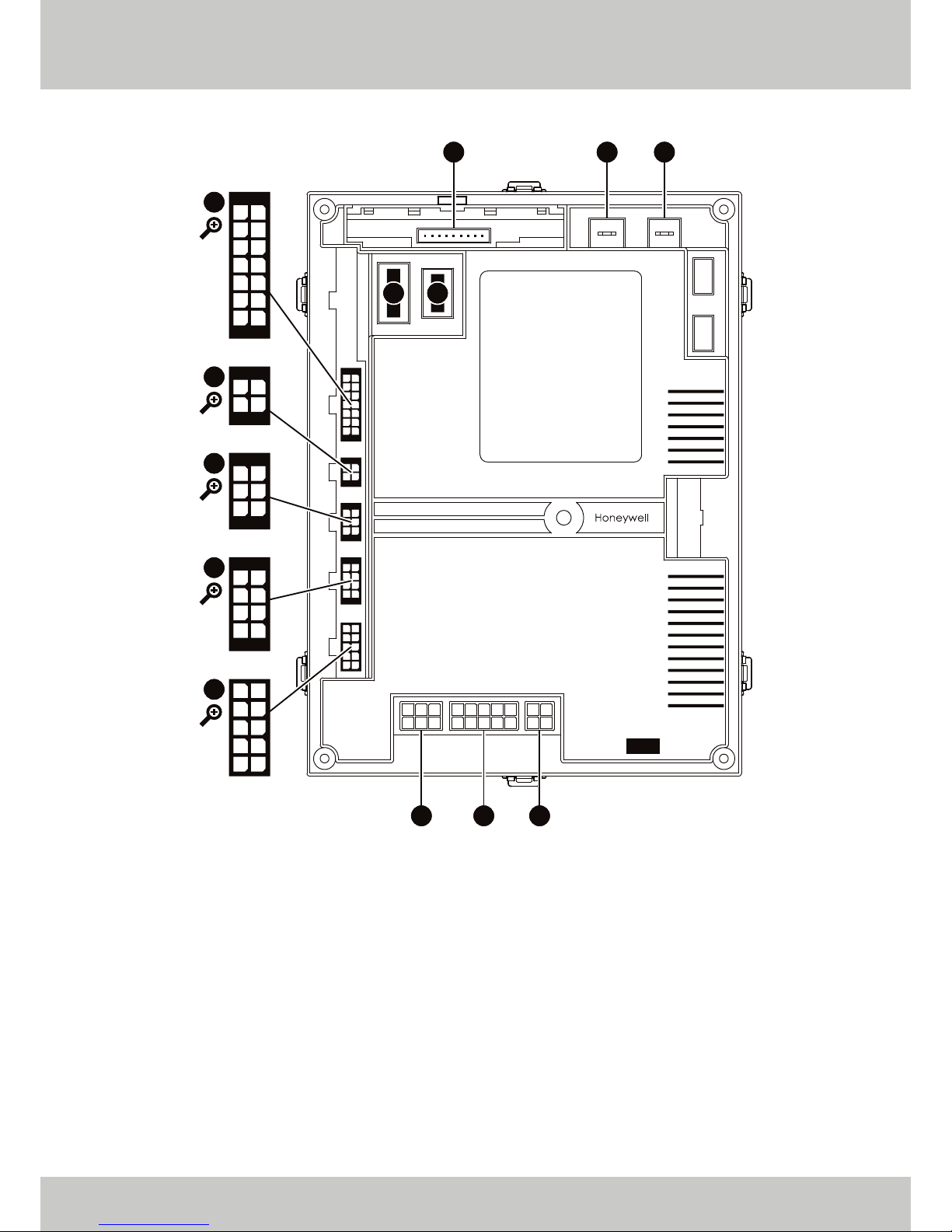
INTERNAL CONTROLS BREAKDOWN (MAIN PCB)
[1]
Used to either power additional pump or motorised valve.
[2]
Only used on ETHOS 70 models.
[3]
Only used on ETHOS 90, 110 and 130 models.
01 02 03
04 05 06
01 02 03 04 05
06 07 08 09 10
01 02
03 04
01
02
03
04
05
06
07
08
09
10
11
12
13
14
01
02
03
04
05
06
07
08
01
02
03
04
05
06
010203
04
01
02
03
04
0510
09
08
07
06
X18 F00 F01
X16 X17
X13
X12
X15
X14
X11
X02 X01 X00
▲ FIGURE 02. TOP VIEW OF MAIN PCB.
• X14 Pin 01: Flue Sensor
[3]
• X14 Pin 05: Flue Sensor
[3]
• X15 Pin 01: Main PCB to Control Fascia
• X15 Pin 02: Main PCB to Control Fascia
• X15 Pin 03: Main PCB to Control Fascia
• X15 Pin 04: Main PCB to Control Fascia
• X15 Pin 05: Main PCB to Control Fascia
• X15 Pin 06: Main PCB to Control Fascia
• X02 Pin 01: Transformer
• X02 Pin 02: Transformer
• X02 Pin 05: Gas Valve Rectified
• X02 Pin 06: Gas Valve Rectified
• X11 Pin 01: AC Fan Interface
• X11 Pin 02: AC Fan Interface
• X11 Pin 04: PWM Supply
• X11 Pin 06: AC Fan Interface
• X11 Pin 07: AC Fan Interface
• X11 Pin 10: PWM Supply
• X13 Pin 01: Pressure Sensor
• X13 Pin 02: Pressure Sensor
• X13 Pin 04: DHW Sensor
• X13 Pin 05: Return Sensor
• X13 Pin 06: Supply Sensor
• X13 Pin 07: Flue Gas High Limit Switch
[2]
• X13 Pin 08: Pressure Sensor
• X13 Pin 11: DHW Sensor
• X13 Pin 12: Return Sensor
• X13 Pin 13: Supply Sensor
• X13 Pin 14: Flue Gas High Limit Switch
[2]
• X00 Pin 01: Power to Main PCB
• X00 Pin 02: Power to Main PCB
• X01 Pin 02: Pump
• X01 Pin 03: 240 V Output
[1]
• X01 Pin 04: 240 V Output
[1]
• X01 Pin 05: Fan Mains
• X01 Pin 07: Pump
• X01 Pin 08: 240 V Output
[1]
• X01 Pin 10: Fan Mains
Page 15
INSTALLATION
TECHNICAL DOCUMENTATION 15
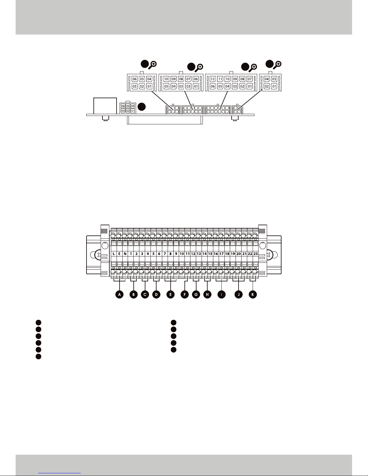
INTERNAL CONTROLS BREAKDOWN (CONTROL FASCIA)
EXTERNAL CONTROLS BREAKDOWN (DIN RAIL)
[1]
Volt Free Connection (UNDER NO CIRCUMSTANCES MUST VOLTAGE BE APPLIED TO THESE CONNECTIONS).
[2]
240 V Output in no DHW Load Condition (0.8 A).
[3]
Used to either power additional Pump or Motorised Valve (0.8 A).
[4]
240 V Output (0.8 A).
[5]
Factory fitted link, do not remove unless utilising 0 - 10 V control.
X06
X01X04
X03
X05
▲ FIGURE 03. TOP VIEW OF CONTROL FASCIA.
• X05 Pin 01: Alarm Output
• X05 Pin 02: Alarm Output
• X05 Pin 05: Reset
• X05 Pin 06: Reset
• X06 Pin 02: Communication with Slave
• X06 Pin 03: Communication with Slave
• X06 Pin 04: Communication with Slave
• X04 Pin 01: 0 - 10 V DC Input
• X04 Pin 02: OpenTherm
• X04 Pin 03: OpenTherm
• X04 Pin 04: External Sensor
• X04 Pin 05: External Sensor
• X04 Pin 06: 0 - 10 V DC Input
• X04 Pin 07: CH Cascade Sensor
• X04 Pin 08: CH Cascade Sensor
• X04 Pin 09: Room Thermostat
• X04 Pin 10: Room Thermostat
• X01 Pin 01: Control Fascia to Main PCB
• X01 Pin 02: Control Fascia to Main PCB
• X01 Pin 03: Control Fascia to Main PCB
• X01 Pin 07: Control Fascia to Main PCB
• X01 Pin 08: Control Fascia to Main PCB
• X01 Pin 09: Control Fascia to Main PCB
• X03 Pin 02: Communication with Master
• X03 Pin 04: Communication with Master
• X03 Pin 05: Communication with Master
▲ FIGURE 04. FRONT VIEW OF DIN RAIL.
A
B
C
D
E
F
Live, Earth and Neutral: Incoming Supply
Connections 1 and 2: Room Thermostat
[1]
Connections 3 and 4: External Sensor
Connections 5 and 6: DHW Thermostat
[1]
Connections 7, 8 and 9
[2]
: DHW Output
[3]
Connection 11
[4]
: Alarm Output
G
H
I
J
K
Connections 12 and 13: 0 - 10 V DC Input
[5]
Connections 14 and 15: OpenTherm
Connections 16, 17 and 18: Communication with Slave
Connections 19, 20 and 21: Communication with Master
Connections 22 and 23: CH Cascade Sensor
Page 16

INSTALLATION
16 TECHNICAL DOCUMENTATION
FLUE CONNECTION
During installation, a choice can be made between a ‘room sealed’ or ‘open flued’ system. The standard two
pipe (eccentric) connections can be easily converted using the Mikrofill adaptor.
The flue gas discharge outlet and air intake system should be installed by a competent installer according to
applicable national and local standards and specifications. When using multiple boilers on a single application,
care should be taken to ensure compliance with the Clean Air Act.
FLUE GAS OUTLET AND AIR INLET PIPE
The air inlet and flue gas outlet pipes may be single wall, smooth or flexible, and be made of:
• Aluminium (air inlet only)
• Plastic
• Stainless Steel
Always consider the large resistance when using flexible material, and also consider condensate formation
due to the suction of cold air.
Diameter of Air Inlet
Diameter of Flue Gas Outlet
The connection for the air supply is on top of the boiler.
The air supply pipe should be air tight. This is to prevent the suction of ‘false air’. Horizontal components in the
air supply should be installed sloping in the direction of the supply opening.
FLUE ADAPTOR INSTALLATION
Please ensure the flue adaptor, when used, is fitted in the correct orientation as shown below:
• Type
• Type
• Type
• Type
• Type
• Type
• Type
Open type appliance without draught stabiliser, air supply from the room, flue gas discharge
outlet above the roof.
Room sealed appliance, connected to concentric air supply / flue discharge through the wall.
Room sealed appliance, connected to concentric air supply / flue discharge through the roof.
Room sealed appliances in cascade, connected to a common concentric air supply / flue
discharge at the appliance.
Room sealed appliance, connected to a seperate air supply and flue discharge pipe, opening
into different pressure areas.
Room sealed appliance, sold without related connecting and / or discharge fittings.
Room sealed appliances in cascade, connected to seperate air supplies but common flue
discharge through the roof.
B23:
C13:
C33:
C43:
C53:
C63:
C83:
▲ FIGURE 05. DIAMETERS OF AIR INLET AND FLUE GAS OUTLET CONNECTIONS.
ETHOS 130
100
100
ETHOS 110
100
100
ETHOS 90
100
100
ETHOS 70
80
80
mm
mm
Page 17

INSTALLATION
TECHNICAL DOCUMENTATION 17
FLUE GAS DATA
The flue gas outlet is located on top of the appliance and is designed for direct connection to a corrosion
resistant flue pipe.
The flue gas discharge pipe to be used should be air tight and water tight at the joints and connections, or
should be seamless. Horizontal components in the flue pipe should be installed sloping in the direction of the
appliance (minimum of 25mm per metre).
Care should be taken when making joints to ensure that the seals are not damaged and the joints must be
sited to enable access / inspection (GasSafe TB 008 Ed. 2.1).
A direct connection to a brick chimney is not permissible unless a suitable liner is installed.
The following table gives the flue gas data for all types:
Average Flue Gas Temperature at Full Load
Maximum Permissable Flue Resistance
FLUE LENGTH
Since the boiler is equipped with a ‘premix burner’ with a fan, an over pressure is created in the boiler. This over
pressure is sufficient to overcome the resistance of the burner, the heat exchanger and the chimney.
The back pressure on the boiler depends on:
• the resistance of the flue pipe.
• the degree of cooling of the combustion gases.
• the resistance of the discharge outlet.
The degree of cooling of the combustion gases depends on the following:
• the insulation value of the flue.
• the ambient temperature.
• the flue system and outlet.
There is a maximum over pressure of around 1.4 mbar (140 Pa) for the ETHOS 70 and 90 and 2.0 mbar (200 Pa)
for the ETHOS 110 and 130 in the boiler for the flue gas discharge system.
The maximum draught permissible is 0.2 mbar (20 Pa), this should be checked with the flue warm and boilers
not firing. If the draught is above this then flue stabilisers are recommended.
CALCULATION OF DIAMETER AND LENGTH
For the calculation and control of the inner diameter of a discharge system with mechanical discharge,
please refer to the applicable national and local standards and regulations.
ETHOS 130
70
204.1
0.058
200
ETHOS 110
70
171.7
0.049
200
ETHOS 90
70
141.3
0.040
140
ETHOS 70
70
109.9
0.031
140
°C
m3/h
kg/s
Pa
▲ FIGURE 06. FLUE GAS DATA / LOAD 100% / FLOW TEMPERATURE 80°C / RETURN TEMPERATURE 60°C
Quantity of Flue Gas at Full Load
Page 18

INSTALLATION
18 TECHNICAL DOCUMENTATION
RESISTANCE TABLE
By using either concentric or the two pipe system, different flue lengths can be achieved. In case a concentric system is used, its length
should not exceed 12 metres.
CONCENTRIC FLUE SYSTEM
Model
Vertical Terminal
Horizontal Terminal
Straight Pipe / m
45° Bend
90° Bend
Vertical Terminal
Horizontal Terminal
Straight Pipe / m
45° Bend
90° Bend
TWO PIPE SYSTEM
Air Inlet
Flue Gas Outlet
Air Inlet
Flue Gas Outlet
Example of Calculation for the ETHOS 70 boiler:
Concentric 45° Bend x 2
Concentric 90° Bend x 1
Concentric Pipe 80/125mm, Vertical 3m + Horizontal 1m = Total 4m Concentric Straight Pipe
Vertical Terminal 80/125mm
Concentric 45° Bend:
Concentric 90° Bend:
Concentric Pipe 80/125mm:
Vertical Terminal 80/125mm:
Total Resistance:
ETHOS 130
-
-
-
-
-
143.4
138.3
14.5
19.9
42.7
-
-
-
-
-
-
-
-
3.4
3.8
16.6
42.0
25.0
6.1
7.0
30.2
ETHOS 110
-
-
-
-
-
94.1
90.7
9.8
13.2
29.4
-
-
-
-
-
-
-
-
2.4
2.7
11.7
35.0
18.0
4.0
4.5
19.5
ETHOS 90
-
-
-
-
-
72.6
70.0
7.3
10.1
21.3
-
-
-
-
-
-
-
-
1.7
1.9
8.4
29.0
12.0
3.1
3.6
15.4
ETHOS 70
65.0
79.7
9.3
12.1
14.6
-
-
-
-
-
4.9
6.8
8.1
36.0
19.0
8.9
12.4
14.7
-
-
-
-
-
-
-
-
▲ FIGURE 07. FLUE DISCHARGE RESISTANCE.
2 x 12.1
1 x 14.7
3 x 9.3
Total resistance is 138.6 Pa, so the boiler output is not changed by the resistance (lower than 140 Pa) and the total concentric
length is less than the maximum allowed 12 metres.
* Vertical terminal length includes 1 metre length.
Resistance
24.2 Pa
14.7 Pa
27.9 Pa
65.0 Pa*
138.6 Pa
2 pcs
1 pcs
3m
RESISTANCE SYSTEM (Pa)mm
80/125
80/125
80/125
80/125
80/125
110/150
110/150
110/150
110/150
110/150
80
80
80
80
80
80
80
80
100
100
100
100
100
100
100
100
Straight Pipe / m
45° Bend R = 0.5 D
90° Bend R = 1.0 D
Vertical Terminal
Horizontal Terminal
Straight Pipe / m
45° Bend R = 0.5 D
90° Bend R = 1.0 D
Straight Pipe / m
45° Bend R = 0.5 D
90° Bend R = 1.0 D
Vertical Terminal
Horizontal Terminal
Straight Pipe / m
45° Bend R = 0.5 D
90° Bend R = 1.0 D
Page 19

INSTALLATION
TECHNICAL DOCUMENTATION 19
CONDENSE CONNECTIONS
The boiler includes an anti syphon condense trap enabling the condense pipework to be taken directly to
drain. The condense water is slightly acidic (pH 3.0 - 5.5) and should be run in a standard drain pipe material,
e.g. acrylonitrile-butadiene-styrene (ABS), polypropylene (PP), polyvinyl chloride (PVC), cross-linked polyvinyl
chloride (PVC-C) or unplasticised polyvinyl chloride (PVC-U).
The condensate pipe should ideally run and terminate internally to a soil stack or waste pipe. Alternatively, the
condensate can be discharged in to the rainwater system or a purpose-made soakaway. Whichever method
is used must conform to applicable national and local standards and regulations. All connecting drainage
pipework should have a fall of at least 2.5° to the horizontal, or approximately 25mm per metre of pipe run. If
the drainage pipe has external run it should be kept to a minimum length with a minimum diameter of 22mm
and be insulated in order to minimise the effects of freezing. It should be noted that connection of a
condensate pipe to a drain may be subject to building controls.
SAFETY VALVE CONNECTION
The discharge pipe from the safety valve shall be self draining and terminate in a visible position where the
discharge cannot result in hazard to any person or to the plant. The size of the discharge pipe shall be no less
than the nominal size of the valve outlet.
HYDRAULIC SYSTEM
The minimum required water circulation over the boiler should be maintained at all times (equivalent to ΔT
25°K at full load). The minimum required water circulation should not be adversely affected by the use of
valves, non-return valves, systems in which several boilers are connected to a common distribution pipe etc.
The maximum water flow is achieved at ΔT 15°K.
Pump Data
* Maximum power consumed is given in Pump Position 03.
The boiler has a pump control circuit. When the boiler is enabled, the pump is switched on. If the boiler is
disabled, the pump will continue to run for a few minutes. The standard run on time is two minutes, but this can
be adjusted.
ETHOS 130
5.57
31.0
40.0
9.0
140
ETHOS 110
4.71
22.5
52.0
29.5
140
ETHOS 90
3.86
24.5
66.0
41.5
140
ETHOS 70
3.00
45.0
82.0
37.0
140
m3/h
kPa
kPa
kPa
W
Nominal Flow Rate (Q)
Boiler Resistance Nominal Flow (R)
Pump Head at Nominal Flow (Q)
Available Head at Nominal Flow (Q)
Maximum Power Consumption*
▲ FIGURE 08. WATER FLOW QUANTITY AND PUMP DATA FOR THE WALL MOUNTED ETHOS RANGE.
ΔT 20°K
Page 20

INSTALLATION
20 TECHNICAL DOCUMENTATION
UPML 25-105 130 PWM
ELECTRICAL DATA: 1 x 230 V, 50 Hz
DIMENSIONAL DRAWINGS AND CONTROL BOX POSITIONS (IN MILLIMETRES)
0.0 0.5 1.0 1.5 2.0 2.5 3.0 3.5 4.0 4.5 5.0
Q [m³/h]
0
2
4
6
8
10
[m]
H
0
20
40
60
80
100
[kPa]
p
0.0 0.2 0.4 0.6 0.8 1.0 1.2 1.4
Q [l/s]
0.0 0.5 1.0 1.5 2.0 2.5 3.0 3.5 4.0 4.5 5.0
Q [m³/h]
0
20
40
60
80
100
120
140
[W]
P1
SPEED
Minimum
Maximum
P1 [W]
3
140
I
1/1
[A]
0.04
1.1
95
130
50
64
131
22
27
112
Page 21

INSTALLATION
TECHNICAL DOCUMENTATION 21
SHUT-OFF VALVES
It is recommended that manual valves should be installed between the flow and return connections to the
installation.
VALVES (BOILERS IN CASCADE ARRANGEMENT)
To prevent water flow through non-firing boilers, and hence unnecessary heat loss, a spring loaded non-return
valve may be installed on the return pipework external to the boiler.
WATER FLOW PROTECTION DEVICE
The boiler is equipped with water flow protection devices. The flow and return sensors ensure that the
protection device is triggered if the water flow is too low.
WATER PRESSURE
At a maximum flow temperature of 90°C and with the nominal water flow that occurs at a ΔT of 20°K, the
minimum operating pressure should be at least 1.5 bar. The operating pressure should be measured when the
pump is switched off. If a lower operating pressure is required, it will be necessary to adjust the maximum flow
temperature.
SYSTEM EXPANSION VESSEL
The size of the expansion vessel is determined by the water volume of the system. We recommend that the
system expansion vessel is installed on the return pipework in a suitable neutral pressure position.
WATER PRESSURE PROTECTION DEVICE
A 3 bar pressure relief valve is integral within the boiler casing. Should it be necessary to protect the system at
a lower pressure, an external safety valve will need to be fitted to the system.
WATER TEMPERATURE
The maximum permissible water flow temperature is 90°C. If the limit thermostat is triggered at 97°C, the boiler
will switch off and will automatically restart when the water temperature falls below the limit temperature that
has been set. The high limit thermostat is set to 100°C and if activated, the boiler will switch off and not
automatically restart when the temperature falls.
WATER QUALITY
The composition and quality of the system water directly affects the performance of any hydronic (water
filled) heating system. The life of the boiler and associated equipment will depend on the correct use of water
treatments and (when required) deaerators, water filters and / or air and dirt separators. This is particularly
important when connecting the boiler into an existing older system.
Care should be taken to ensure that pipework is sound and leaks are eliminated, thus reducing the need for
fresh ‘top up’ water to a minimum.
Page 22

INSTALLATION
OPERATING INSTRUCTIONS
22 TECHNICAL DOCUMENTATION
WATER HARDNESS
Water hardness levels are caused by dissolved minerals in the water and will vary geographically. The harder
the water, the more likely that problems with precipitation (limescale deposits) will occur, causing permanent
damage to the boiler and associated equipment. This is a system fault and is not covered by warranty.
The water hardness is generally expressed in terms of ‘ppm’ (parts per million) and is sub-divided as follows;
• Very Soft: < 50 ppm
• Soft: 50 - 160 ppm
• Moderately Hard: 160 - 250 ppm
• Hard and Very Hard: > 250 ppm
The system should contain soft to moderately hard water, with a water hardness that does not exceed 250
ppm at a flow temperature of 80°C and ΔT 20°K. Before supplying water, the hardness and chloride value of
the system water should always be determined.
The chloride value should never exceed 200mg/litre.
If the chloride value does exceed this value, the cause should be determined. Compare the chloride value
of the supply water and the central heating system water. If this content is much higher, and if no materials
containing chloride have been added, this indicates evaporation. If the chloride content is very high, the
water is rendered more aggressive (this can be caused by, amongst other things, improperly regenerated
water softener). The system should be flushed clean and filled with low chloride water.
In order to counter unnecessary wear and tear and blockages due to impurities present in the system, we
recommend the use of a filter system with a mesh size of 100 microns. Always place this in the return line of the
secondary part of the system. In order to guarantee a properly working system and long life, one should
remove suspended and corrosive particles by installing a suitable filter.
Periodic inspection, including analysis of the system water and cleaning of the filters, should be performed.
OPERATION
The fan, which is modulated by the temperature controller, supplies the combustion air. Due to the resultant
under pressure in the venturi, the zero pressure controller in the gas valve mixes in the required quantity of gas.
Gas and air are completely mixed in the venturi, and the gas-air mixture is then fired directly into the burner.
The fan also removes the combustion gases. The boiler has no lower limit to the return water temperature. If
the temperature is low, condensate will be formed, which is removed via the discharge system.
CONTROLS
Depending on the heat requirement of the system, the boiler output will automatically modulate between
10% and 100% (10:1 turn down ratio). Below 10% load, the boiler operates on / off, based on temperature.
Page 23

OPERATING INSTRUCTIONS
TECHNICAL DOCUMENTATION 23
BOILER MODULE
PCB SYMBOL KEY
01
02
DHW Selection
DHW Temperature
03
04
Heating Selection
Heating Temperature
05
06
Multi-Function
Power Switch
07
Reset Switch
- Heating Circuit Active
- Summer Mode
- Pump Active
- Burner Operating
- DHW Disabled
- DHW Active
- OpenTherm Connection
- Information
- Wireless
- Reset Required
- Engineer Function Active
- Standby
- Frost Protection
RESET
RESET
RESET
BAR
04 02
06 07
03 05 01
Page 24

OPERATING INSTRUCTIONS
24 TECHNICAL DOCUMENTATION
WARNING:
• The appliance should be installed by a competent installer.
• These operating instructions should be closely followed.
• If the cause of any fault cannot be determined, please contact the technical department.
• Never carry out repairs unless you are a competent and qualified engineer.
SWITCHING ON THE APPLIANCE:
• STEP 01:
• STEP 02:
• STEP 03:
SWITCHING OFF THE APPLIANCE:
The appliance can be switched off in one of four ways:
• METHOD 01:
• METHOD 02:
• METHOD 03:
• METHOD 04:
Open the gas valve.
Switch on the boiler using the power switch on the control panel.
Press the button to enable the heating function.
Press the button to enable the DHW function if required.
The boiler will remain available for hot water operation.
Use the button.
The heating function will be disabled, whilst leaving the DHW function available.
The boiler will remain available for heating operation.
Use the button.
The hot water function will be disabled, whilst leaving the heating function active.
The boiler will remain on but neither heating or DHW functions are active.
Use the and buttons.
Both the heating and DHW functions will be disabled.
Switch off the boiler completely.
• STEP 01:
• STEP 02:
Switch off the boiler using the power switch on the control panel.
Close the gas valve.
Page 25

OPERATING INSTRUCTIONS
TECHNICAL DOCUMENTATION 25
INFORMATION DISPLAY:
DHW OPERATION
• DHW Mode can be enabled or disabled by using the button.
• The DHW setpoint can be increased or decreased by using the buttons.
HEATING OPERATION
• Heating Mode can be enabled or disabled by using the button.
• The CH setpoint can be increased or decreased by using the buttons.
DISPLAYING INFORMATION
• The installer menu can be accessed by pressing and holding for three seconds.
• The parameter number will then be displayed, followed by the value.
• The next parameter can be viewed by utilising the buttons.
TABLE PARAMETER LIST
RESET
RESET
BAR
INDEX
P01
P02
P03
P04
P05
P06
P07
P08
P09
P10
P11
P12
P13
P14
P15
P16
P17
VARIABLE
Flame Current
CH Supply Temperature
CH Return Temperature
N/A
Water Pressure
Output Level
Requested Fan Speed
Actual Fan Speed
Exhaust Temperature
Cascade Temperature
OTC Temperature
Cascade Modulation Level
CH Control Setpoint
DHW Control Setpoint
Total Burners
Total Burners On
Total Displays
UNIT
[μA]
[°C -or- °F]
[°C -or- °F]
N/A
[bar/10 -or- psi] (local MAXSYS0, where sensor is connected)
[rel. %] actual relative output level of the burner
[50*rpm] speed requested by control algorithm
[50*rpm] fan speed
[°C]
[°C -or- °F] if cascade sensor is connected
[°C -or- °F] temperature from external sensor
[rel. %] relative modulation level of cascade
[°C -or- °F]
[°C -or- °F]
total count of installed burners
count of burners running
total count of boiler modules
Page 26

OPERATING INSTRUCTIONS
26 TECHNICAL DOCUMENTATION
HISTORY MODE
• To access history mode, press and hold until the display shows ‘Bu 0’.
• Press the button and the display will flash ‘Hi 0’.
• The error code will then automatically be displayed after a few seconds.
• The index number can be cycled using the buttons.
• To exit history mode, press and hold the button.
POSSIBLE ERROR CODES
continued on page 27...
ERROR CODE
01
02
03
05
07
08
09
13
15
16
17
18
30
31
32
33
34
37
DESCRIPTION
Flame lockout after several ignition
attempts.
False flame signal.
High limit temperature.
Fan speed signal not recognised.
Flue gas temperature sensor limit
exceeded.
Flame circuit error / loss of flame.
Gas valve circuit error.
Reset error.
Supply / return limit error.
Stuck at test error - supply sensor.
Stuck at test error - return sensor.
Cracked sensor test error.
Flow temperature sensor short
circuit.
Flow temperature sensor open
circuit.
DHW sensor short circuit.
DHW sensor open circuit.
Low incoming mains voltage.
Water pressure too low.
RESOLUTION
The boiler has attempted to fire but has not registered an ionisation
signal. If the burner is not lighting, then check for an ignition spark and
that the gas valve is opening. If the burner is lighting, then the ionisation
signal is not being recognised. Check the ionisation probe, cap and
cable for continuity and cleanliness. Also, check for continuity on the
condensate trap earth pins.
The boiler has detected an ionisation signal when not firing. Check the
ionisation probe, cap and cable for continuity and cleanliness.
The boiler flow temperature has exceeded the high limit temperature.
Check for a lack of pressure in the system or a lack of flow, and confirm
pump circulation.
A fan speed signal is not being received when the fan is being
powered. Check the tacho cable running from the fan to the main
PCB, and confirm that the fan is operating.
The flue gas temperature has exceeded the limit temperature. Check
the heat exchanger for blockages and for cleanliness. Also, check for
system flow.
The ionisation signal has been lost during operation. Check for a lack of
gas, poor combustion and rectification of the ionisation signal including
the ionisation probe, cap and cable.
The gas valve has failed the circuit test. Check the wiring connections
and replace either the valve or cable.
The reset has been operated more than five times in fifteen minutes.
The boiler has failed the temperature sensor drift test. The sensor
readings have passed outside the allowable limits.
The sensor reading has not changed by ± 0.25°C for 24 hours. The boiler
will automatically restart and a second test is carried out lasting 240
minutes. If both tests fail, the boiler will go into a lockout condition. If
either test passes, then the boiler will continue to operate.
The sensor has detected a physical crack, replace the sensor.
The flow temperature sensor is registering a short circuit. Check the
connection to the sensor and replace the sensor if necessary.
The flow temperature sensor is registering an open circuit. Check the
connection to the sensor and replace the sensor if necessary.
The DHW sensor is registering a short circuit. Check the connection to
the sensor and replace the sensor if necessary.
The DHW sensor is registering an open circuit. Check the connection to
the sensor and replace the sensor if necessary.
The incoming voltage has dropped below 157 V. Investigate and
rectify the incoming mains voltage issue.
The internal pressure sensor has detected that the water pressure has
dropped too low. Check the water pressure and increase it if
necessary. Check the sensor for a blockage.
Page 27

OPERATING INSTRUCTIONS
TECHNICAL DOCUMENTATION 27
POSSIBLE ERROR CODES continued.
Several checks are included to protect the boiler and its environment. The water pressure sensor is monitored
continually for primary water condition checks, temperatures are monitored continually if they are in range,
safety times are constantly compared etc.
Any violation of (programmable) limits (and / or internal thermostat functions) will lead to an error / fault
warning condition. This condition can be shown on the display and via external controls connections. Severe
error (i.e. igniter lockout) will cause a lockout condition which can only be cleared by the reset switch on the
boiler control panel. Non severe errors / faults (i.e. sensor out of range) will reset as soon as the cause of the
problem is rectified. In case of lockout and blocking conditions, the fan will not operate and the pump will
always be on (only in a case of low water pressure will the pump be disabled).
ERROR CODE
43
44
45
46
47
80
81
95
96
97
98
99
DESCRIPTION
Return temperature sensor short
circuit.
Return temperature sensor open
circuit.
Flue gas sensor short circuit.
Flue gas sensor open circuit.
Water pressure sensor fault.
Supply and return sensor reversed.
Drift test warning.
Cascade header sensor not
connected.
Outside air sensor fault.
Cascade structure mismatch.
Communication error between
control fasciae.
Communication error between
main PCB and control fascia.
RESOLUTION
The return temperature sensor is registering a short circuit. Check the
connection to the sensor and replace the sensor if necessary.
The return temperature sensor is registering an open circuit. Check the
connection to the sensor and replace the sensor if necessary.
The flue gas temperature sensor is registering a short circuit. Check the
connection to the sensor and replace the sensor if necessary.
The flue gas temperature sensor is registering an open circuit. Check
the connection to the sensor and replace the sensor if necessary.
The boiler cannot detect the water pressure. Check the wiring to the
sensor and replace the sensor if necessary.
The return temperature sensor reading is greater than the flow
temperature sensor reading. Check for a lack of flow or reverse flow
through the boiler.
A test function is being carried out on the flow and return temperature
sensors.
The cascade header sensor has not been detected by the master
boiler. Check the wiring to the boiler and the condition of the sensor.
The boiler has detected a fault on the outside air sensor. Check for
connection to the boiler and also check the condition of the sensor.
The master boiler has detected a change in the number of connected
boilers / burners. Perform an auto detect sequence and check the
wiring and condition of other boilers / burners.
Communication between two control fasciae has been interrupted.
Check the wiring of the control fasciae, and check the fuses and
power supplies to the fasciae. Perform an auto detect sequence.
Communication between the main PCB and control fascia has been
interrupted. Check the wiring between the main PCB and control
fascia, check the fuses on the main PCB, and perform an auto detect
sequence. This may require replacement of either the main PCB or the
control fascia.
Page 28

COMMISSIONING
28 TECHNICAL DOCUMENTATION
GENERAL
The commissioning should only be carried out by qualified personnel. The guarantee may be void if this is not
adhered to.
Before operating the appliance, the following should be done:
• Switch off the electrical power supply of the appliance.
• Remove the casing front panel.
• Check the leak tightness of the gas connection.
• Check whether the electrical connection, including earthing, has been correctly made.
• Also, check whether the phase (L) has been connected properly. The boiler is phase sensitive.
• Fill the appliance and system with water.
• Fill the condensate trap with water.
• Check the flue gas discharge connection and, if present, the air supply connection.
• Open the gas valve and vent the gas pipe.
• Switch on the electrical power supply of the appliance.
• Check the built-in pump.
• Check the boiler at maximum load.
Start the boiler. Allow the boiler to run and stabilise (around three minutes). At full load, the following settings
should be checked and corrected if necessary:
REFERENCE VALUE FOR MAXIMUM LOAD
Reference value for CO2:
Reference value for CO:
Measure the gas pressure before the gas valve. At maximum load, this must be at least 17 mbar for natural
gas and 30 mbar for propane. If there are several boilers, this pressure should be measured with all boilers
operating at maximum load.
Check the water side temperature difference (ΔT) between the flow and return connections of the boiler. The
ΔT should be between 15°K and 25°K at full load.
Check the boiler at minimum load. At minimum load, the following settings should be checked and corrected
if necessary:
REFERENCE VALUE FOR MINIMUM LOAD
Reference value for CO2:
Reference value for CO:
8.4% ± 0.2
9.5% ± 0.2
< 50 ppm
< 70 ppm
8.4% ± 0.2
9.5% ± 0.2
< 10 ppm
< 10 ppm
(natural gas)
(propane)
(natural gas)
(propane)
(natural gas)
(propane)
(natural gas)
(propane)
G20, G25
G31
G20, G25
G31
G20, G25
G31
G20, G25
G31
Page 29

COMMISSIONING
TECHNICAL DOCUMENTATION 29
MAXIMUM LOAD ADJUSTMENT
Press and hold the button for three seconds until the below display appears, the boiler will then start to
operate at minimum load.
To adjust to maximum rate, press and hold until the below display appears, the boiler will then start to
operate at maximum load.
MINIMUM LOAD ADJUSTMENT
Press and hold the button for three seconds until the below display appears, the boiler will then start to
operate at minimum load.
If the boiler is already operating at maximum load (displaying ‘t 100’), then press and hold until the
display reads as above.
To return to normal operating mode, press and hold for three seconds until the boiler returns to the
temperature display.
Page 30

COMMISSIONING
30 TECHNICAL DOCUMENTATION
SETTING THE CO2 VALUE FOR THE ETHOS RANGE
• Any adjustments should only be carried out by competent persons.
• After adjustment of the gas valve the adjusters must be resealed.
There is a setting screw on the gas valve with which the CO2 value can be set at maximum load. Set the boiler
at maximum load and check the CO2 value. If necessary, adjust the flat setting screw; clockwise gives less
CO2, anti-clockwise gives more CO2.
There is a Torx setting screw on the gas valve with which the CO2 value can be set at minimum load. Set the
boiler at minimum load and check the CO2 value. If necessary, adjust the Torx setting screw; clockwise gives
more CO2, anti-clockwise gives less CO2.
After the CO2 values have been set, they should be checked once again and corrected if necessary.
GAS VALVE:
FLUE GAS ANALYSER TEST POINT (ETHOS 90, 110 AND 130):
When setting the CO2 levels on the boiler, the
readings can be taken from the flue gas
temperature sensor tapping. Disconnect the
electrical connection from the sensor. Unscrew the
sensor and remake the electrical connection.
Upon completion of tests, replace the flue gas
temperature sensor in reverse order to that
described above.
Page 31

COMMISSIONING
TECHNICAL DOCUMENTATION 31
CASCADE SET-UP
CONVERSION FROM NATURAL GAS TO PROPANE
For the ETHOS 90, a 6mm throttle ring will be required. This should be installed between the gas valve and the
venturi. After the conversion, the CO2 value should be set at full and minimum fire.
For the ETHOS 70, 110 and 130 it is only necessary to change the CO2 values on the gas valve at full and
minimum fire.
AUTO DETECTION MODE
Cascade structure will need to be auto detected prior to cascading the boilers. Once the boilers have been
detected as indicated below, the number of burners can be confirmed by following the steps below.
•
•
•
•
•
Press and hold the button for three seconds and the display will show:
Once the additional boilers have been identified, the display will change again to indicate it is
loading the parameters to the slave boiler(s).
Once these have been loaded, the master boiler will then request confirmation of the total number
of burners.
This can be confirmed by pressing the button.
Once confirmed, the master boiler will display the normal control display and the slave boiler(s) will
display ‘SLA’ and then the boiler number.
MASTER BOILER SLAVE BOILER 01 SLAVE BOILER 02
Page 32

CASCADE SET-UP
32 TECHNICAL DOCUMENTATION
CASCADE TEST MODE
•
•
•
•
•
Press and hold the and buttons together for three seconds.
This will send a request to the master boiler to fire all slave boilers.
This can be increased to 100% by pressing the button until the display below is shown.
This test mode can be cancelled by pressing and holding the and buttons again.
These buttons should be held until the display returns to the standard display.
Page 33

MAINTENANCE
TECHNICAL DOCUMENTATION 33
SAFETY
Maintenance should only be carried out by competent persons. Always isolate the gas supply at the gas
service valve and isolate and disconnect the electrical supply prior to the removal of any components. Ensure
that all external controls are isolated. After completion of maintenance or component replacement the
following should be checked:
•
•
•
•
•
•
SERVICING SCHEDULE
To ensure the safe and efficient operation of the appliance, it is recommended that it is checked at regular
intervals and maintained as necessary. The frequency of maintenance will depend upon the installation
condition and usage, but should still be carried out at least annually. Mikrofill Systems Ltd. does not accept
liability resulting from the use of unauthorised components for the repair and maintenance of appliances not
in the companies recommendations and specifications.
•
•
•
•
•
•
•
•
Test for gas soundness.
Check the water system is correctly filled and free of air. Air in the boiler could cause damage to the
heat exchanger. For this reason, the automatic air vent in the ETHOS 90, 110 and 130 must be left
open, whilst the ETHOS 70 should be manually vented.
With the system hot, check the boiler for signs of water leakage.
Check the gas rate and measure the CO2 content to ensure it is within the specified range. Adjust if
necessary (see COMMISSIONING section on page 28).
Carry out functional tests.
If in the unlikely event there is a component failure, please refer to pages 34 - 37 for instructions on
removal of major components.
Light the boiler and carry out function checks, noting any operational faults.
Run the system up to operating temperature then check the gas consumption rate. Refer to page
29 for how to operate the boiler at maximum rate.
Connect a suitable flue gas analyser to the flue gas test point (see page 30) and check the CO2
values are within those specified in the COMMISSIONING section. If the values are correct and the
CO / CO2 ratio is within legal limits, then no further action is required. If the values are incorrect,
remove and clean the burner as described on pages 35 and 36.
Inspect the heat exchanger. If there are any signs of debris, vacuum the heat exchanger and flush
through with water.
Inspect the ignition electrode and ionisation probe, and replace if necessary.
Flush the condensate trap through with water.
Check that the flue terminal is unobstructed and that the flue system is sealed correctly.
After completing maintenance, carry out safety checks as described above.
Page 34

MAINTENANCE
34 TECHNICAL DOCUMENTATION
REMOVAL OF GAS VALVE AND VENTURI
• Isolate the gas and electrical supplies to the boiler.
• Remove the four bolts from the elbow flange on the rear of the gas valve ( ).
• Remove the electrical connection on the gas valve.
• Remove the three bolts (ETHOS 70 - 110) or the six screws (ETHOS 130) from the venturi / fan ( ).
• Remove the gas valve / venturi assembly from the boiler.
• To separate the gas valve and venturi, remove the four bolts on the assembly ( ).
• Replace in reverse order ensuring all seals / gaskets are in good condition (renew if necessary).
Page 35

MAINTENANCE
TECHNICAL DOCUMENTATION 35
REMOVAL OF THE FAN AND BURNER ASSEMBLY (ETHOS 70)
• Isolate the gas and electrical supplies to the boiler.
• Remove the caps from the ignition electrode and ionisation probe.
• Remove the gas valve and venturi as descibed on page 34.
• Remove the two electrical connections from the fan.
• Remove the four nuts from the burner door ( ).
• Extract the burner / fan assembly.
• To separate the fan from the burner, remove the four screws from the fan ( ).
• Replace in reverse order ensuring all seals / gaskets are in good condition (renew if necessary).
Page 36

MAINTENANCE
36 TECHNICAL DOCUMENTATION
REMOVAL OF THE FAN AND BURNER ASSEMBLY (ETHOS 90, 110 AND 130)
• Isolate the gas and electrical supplies to the boiler.
• Remove the caps from the ignition electrode and ionisation probe.
• Remove the gas valve and venturi as descibed on page 34.
• Remove the two electrical connections from the fan.
• Remove the six nuts from the burner door ( ).
• Extract the burner / fan assembly.
• To separate the fan from the burner, remove the four screws from the fan ( ).
• Replace in reverse order ensuring all seals / gaskets are in good condition (renew if necessary).
Page 37

MAINTENANCE
TECHNICAL DOCUMENTATION 37
REMOVAL OF PUMP / PUMP HEAD
• Isolate the gas and electrical supplies to the boiler.
• Isolate and drain water from the boiler.
• Disconnect the electrical supplies from the pump.
• To completely remove the pump, unscrew the pump unions ( ) and extract the pump.
• To remove the pump head, remove the four screws ( ) and separate the head from the base.
• Replace in reverse order ensuring all seals / gaskets are in good condition (renew if necessary).
Page 38

MAINTENANCE
38 TECHNICAL DOCUMENTATION
SETTING / CHECKING OF IGNITION ELECTRODE AND IONISATION PROBE GAPS
In addition to the annual maintenance, please ensure the following is carried out:
• Isolate the gas and electrical supplies to the boiler.
• Check the gaps between the ignition electrode / ionisation probe and burner as indicated below.
• Adjust the gaps as necessary.
▲ FIGURE 09. BACK VIEW OF THE BURNER DOOR.
8 - 10mm
3 - 4mm
8 - 10mm
Page 39

COMPONENT LIST
TECHNICAL DOCUMENTATION 39
Any components within the ETHOS 70 - 130 that may require replacing have been listed in this section, along
with their respective part codes. If any part needs replacing which is not listed here, please contact our
technical department on 03452 60 60 20 for assistance.
CASING AND ELECTRICAL COMPONENTS
“(PART CODE) PART NAME”:
▲ FIGURE 10. EXPLODED DRAWING DETAILING THE CASING AND ELECTRICAL COMPONENTS OF THE ETHOS 70 - 130.
(WHB000067)
(WHB300029)
(WHB000068)
(WHB300020)
(WHB000154)
(WHB000069)
(WHB000070)
(WHB200026)
(WHB000071)
(WHB300021)
(WHB000072)
(WHB300022)
(WHB000073)
(WHB200027)
(WHB300023)
(WHB000074)
CASING - BACK PANEL (ETHOS 70 - 90)
CASING - BACK PANEL (ETHOS 110 - 130)
CASING - BOTTOM PANEL (ETHOS 70 - 90)
CASING - BOTTOM PANEL (ETHOS 110 - 130)
CASING - CONTROL COVER PANEL
CASING - CONTROL PANEL
CASING - FRONT PANEL
CASING - HEAT EXCHANGER BRACKET
(ETHOS 90 - 130)
CASING - LEFT SIDE PANEL (ETHOS 70 - 90)
CASING - LEFT SIDE PANEL (ETHOS 110 - 130)
CASING - RIGHT SIDE PANEL (ETHOS 70 - 90)
CASING - RIGHT SIDE PANEL (ETHOS 110 - 130)
CASING - TOP PANEL (ETHOS 70)
CASING - TOP PANEL (ETHOS 90)
CASING - TOP PANEL (ETHOS 110 - 130)
CASING - WALL HANGING BRACKET
01
02
03
04
05
06
07
08
09
10
(WHB000088)
(WHB000089)
(WHB000077)
(WHB000078)
(WHB000091)
(WHB000084)
(WHB200028)
(WHB000080)
(WHB000126)
(WHB000171)
(WHB000092)
(WHB700093)
(WHB900093)
(WHB110093)
(WHB130093)
CONTROL FASCIA PCB (DSP)
CONTROL RESET SWITCH WITH WIRE SET
DOOR CATCH
DOOR PIN (M6)
ELECTRICAL ISOLATION SWITCH
FLUE SEAL (Ø 90mm) (ETHOS 70)
FLUE SEAL (Ø 110mm) (ETHOS 90 - 130)
HANDLE - BLACK (PLASTIC)
HT IGNITION LEAD (ORANGE) (NOT PICTURED)
HT IONISATION LEAD (BLACK) (NOT PICTURED)
IGNITION TRANSFORMER
MAIN PCB (MAXSYS) (ETHOS 70)
MAIN PCB (MAXSYS) (ETHOS 90)
MAIN PCB (MAXSYS) (ETHOS 110)
MAIN PCB (MAXSYS) (ETHOS 130)
11
12
13
14
15
16
17
18
19
20
21
02
08
15
16
01
05
07
09
13
14
13
14
20
10
21
04
11
17
06
03
12
Page 40

COMPONENT LIST
40 TECHNICAL DOCUMENTATION
CORE COMPONENTS (ETHOS 70)
* for details of individual components within this sub-assembly please contact Mikrofill Systems Ltd. on 03452 60 60 20.
“(PART CODE) PART NAME”:
▲ FIGURE 11. EXPLODED DRAWING DETAILING THE CORE COMPONENTS OF THE ETHOS 70.
01
02
03
04
05
06
07
08
09
10
11
12
13
14
15
16
17
18
(WHB000204)
(WHB100001)
(WHB000002)
(WHB300003)
(WHB000045)
(WHB000044)
(WHB000043)
(WHB000046)
(WHB000004)
(WHB000005)
(WHB300018)
(WHB000006)
(WHB000007)
(WHB300005)
(WHB300006)
(WHB300007)
(WHB300008)
(WHB000013)
AIR INLET TUBE (Ø 76mm) (500mm) (ETHOS 70)
BURNER DOOR COMPLETE (ETHOS 70)
BURNER DOOR MOUNTING NUT
COMBUSTION FAN NRG 137 (ETHOS 70 - 110)
CONDENSATE HOSE (Ø 22.8mm) (250mm)
CONDENSATE HOSE (Ø 22.8mm) (350mm)
CONDENSATE HOSE (Ø 22.8mm) (600mm)
CONDENSATE HOSE (SILICONE) (400mm) (ETHOS 70)
CONDENSE SYPHON / TRAP
DRAIN TAP (½”)
ELBOW FLANGE (¾”)
FAN GASKET (ETHOS 70 - 110)
FLUE GAS TEST POINT CAP (ETHOS 70)
GAS PIPE GASKET
GAS VALVE
GAS VALVE GASKET
GAS VALVE RECTIFICATION LEAD
GRUNDFOS UPML 25-105 130 OEM PUMP
19
20
21
22
23
24
25
26
27
28
29
30
31
32
33
34
35
36
(WHB100002)
(WHB000172)
(WHB000020)
(WHB000021)
(WHB000022)
(WHB000023)
(WHB000029)
(WHB000030)
(WHB000031)
(WHB000058)
(WHB000032)
(WHB300011)
(WHB000155)
(WHB000173)
(WHB000202)
(WHB000203)
(WHB000038)
(WHB000200)
HEAT EXCHANGER (ETHOS 70)
HIGH LIMIT SWITCH (ETHOS 70)
IGNITION ELECTRODE (ETHOS 70)
IGNITION ELECTRODE / IONISATION PROBE CAP
IGNITION ELECTRODE / IONISATION PROBE GASKET
IONISATION PROBE (ETHOS 70)
PRESSURE RELIEF VALVE (3 BAR) (¾”)
PRESSURE SENSOR
PUMP GASKET
PUMP UNION (1” - 1½”) (ETHOS 70)
RUBBER SEAL (SEALED AIR INLET BOX)
SEALED AIR INLET BOX
SEALED AIR INLET TRAP (HEPVO) COMPLETE*
TARGET WALL INSULATION (NOT PICTURED)
TARGET WALL INSULATION SCREW (NOT PICTURED)
TARGET WALL INSULATION WASHER (NOT PICTURED)
TEMPERATURE SENSOR (LONG)
VENTURI (ETHOS 70 - 90)
36
01
20
15
14
17
16
11
03
03
03
03
22
22
24
21
23
23
02
32
04
12
19
13
35
25
08
07
09
29
30
05
31
31
31
31
31
31
06
26
35
28
27
18
27
28
10
Page 41

COMPONENT LIST
TECHNICAL DOCUMENTATION 41
CORE COMPONENTS (ETHOS 90, 110 AND 130)
* for details of individual components within this sub-assembly please contact Mikrofill Systems Ltd. on 03452 60 60 20.
“(PART CODE) PART NAME”:
▲ FIGURE 12. EXPLODED DRAWING DETAILING THE CORE COMPONENTS OF THE ETHOS 90 - 130.
02
11
12
13
(WHB200014)
(WHB300013)
(EFD000006)
(WHB200033)
(WHB400007)
(WHB000002)
(WHB200015)
(WHB300003)
(WHB400003)
(WHB000045)
(WHB000044)
(WHB000043)
(WHB200016)
(WHB300014)
(WHB000004)
(WHB000005)
(WHB300018)
(WHB000006)
(WHB400004)
(WHB300005)
(WHB300006)
(WHB300007)
(WHB300008)
(WHB000013)
AIR INLET TUBE (Ø 76mm) (750mm) (ETHOS 90)
AIR INLET TUBE (Ø 76mm) (850mm) (ETHOS 110 - 130)
AIR VENT VALVE (⅜” MALE)
BURNER DOOR COMPLETE (ETHOS 90 - 110)*
BURNER DOOR COMPLETE (ETHOS 130)*
BURNER DOOR MOUNTING NUT
CLEAR HOSE (AIR VENT VALVE TO DRAIN) (NOT PICTURED)
COMBUSTION FAN NRG 137 (ETHOS 70 - 110)
COMBUSTION FAN RG 175 (ETHOS 130)
CONDENSATE HOSE (Ø 22.8mm) (250mm)
CONDENSATE HOSE (Ø 22.8mm) (350mm)
CONDENSATE HOSE (Ø 22.8mm) (600mm)
CONDENSATE HOSE (SILICONE) (500mm) (ETHOS 90)
CONDENSATE HOSE (SILICONE) (320mm) (ETHOS 110 - 130)
CONDENSE SYPHON / TRAP
DRAIN TAP (½”)
ELBOW FLANGE (¾”)
FAN GASKET (ETHOS 70 - 110)
FAN GASKET (ETHOS 130)
GAS PIPE GASKET
GAS VALVE
GAS VALVE GASKET
GAS VALVE RECTIFICATION LEAD
GRUNDFOS UPML 25-105 130 OEM PUMP
04
05
06
07
09
01
03
08
10
17
18
19
14
15
16
23
24
25
26
27
28
29
30
31
32
33
35
36
37
38
39
(WHB200006)
(WHB300009)
(WHB400005)
(WHB200007)
(WHB000021)
(WHB000022)
(WHB200008)
(FSB500011)
(WHB200038)
(WHB000029)
(WHB000030)
(WHB000031)
(WHB200022)
(WHB200011)
(WHB000032)
(WHB300011)
(WHB000155)
(WHB000173)
(WHB000202)
(WHB000203)
(WHB000038)
(WHB200012)
(WHB000200)
(WHB300012)
(WHB400009)
HEAT EXCHANGER (ETHOS 90)
HEAT EXCHANGER (ETHOS 110)
HEAT EXCHANGER (ETHOS 130)
IGNITION ELECTRODE (ETHOS 90 - 130)
IGNITION ELECTRODE / IONISATION PROBE CAP
IGNITION ELECTRODE / IONISATION PROBE GASKET
IONISATION PROBE (ETHOS 90 - 130)
OVERHEAT STAT (BURNER DOOR) (ETHOS 90 - 130)
OVERHEAT STAT (REAR OF HEAT EXCHANGER) (ETHOS 90 - 130)
PRESSURE RELIEF VALVE (3 BAR) (¾”)
PRESSURE SENSOR
PUMP GASKET
PUMP UNION (1¼” - 1½”) (ETHOS 90 - 130)
PUSH FIT - STRAIGHT (CYLINDRICAL)
RUBBER SEAL (SEALED AIR INLET BOX)
SEALED AIR INLET BOX
SEALED AIR INLET TRAP (HEPVO) COMPLETE*
TARGET WALL INSULATION (NOT PICTURED)
TARGET WALL INSULATION SCREW (NOT PICTURED)
TARGET WALL INSULATION WASHER (NOT PICTURED)
TEMPERATURE SENSOR (LONG)
TEMPERATURE SENSOR (SHORT)
VENTURI (ETHOS 70 - 90)
VENTURI (ETHOS 110)
VENTURI (ETHOS 130)
20
21
22
40
34
15
01
11
28
09
24
02
03
03
03
03
03
03
04
x 06
06
07
08
18
10
12
13
14
16
17
19
20
21
22
22
23
23
25
26
27
29
29
30
30
31
32
33
34
34
34
34
34
34
38
38
39
40
Page 42

CONVERSION FORMULAE & FACTORS
42 TECHNICAL DOCUMENTATION
FORMULAE
11.7% CO2 is the maximum CO2 percentage that is generated by stoichiometric burning of G20 natural gas
(H-gas).
Excess Air N:
CONVERSION FACTORS
• For NOx 1 ppm = 2.05 mg/m3 = 1.759 mg/kWh = 0.498 mg/MJ
• For CO 1 ppm = 1.24 mg/m3 = 1.064 mg/kWh = 0.298 mg/MJ
EXAMPLE
Measured values for an environmentally friendly unit:
• NO
x
• CO
2
What is the value for NOx according to the most usual standard in mg/kWh for N = 1?
NOx (for N = 1) =
15.0 x 1.17 = 17.6 ppm
17.6 x 1.759 = 30.9 mg/kWh
• 1 kcal
• 1 kWh
EFFICIENCY AT THE FLUE GAS SIDE
The difference between gross and nett calorific values is the heat of evaporation of the combustion
produced water. At 298.15°K (25°C), this is 2442.5 kJ/kg (583.38 kcal/kg).
20.9
20.9 - measured O
2
CO2 = x 11.7
11.7
measured CO2 x 20.9
O2 = 20.9 -
20.9 - measured O
2
20.9
N = x 0.914
CO2 measured
11.7
N = 1 + x 0.914
(N = 1):
(N = 1):
= 15 ppm
= 10%
11.7
10 x 20.9
O2 = 20.9 - = 3%
20.9 - 3
20.9
N = = 1.17
Watts (W)
1
1.163
0.293
kcal/h
0.86
1
0.252
Btu/h
3.41
3.97
1
▲ FIGURE 13. CONVERSION FACTORS.
= 4.187 kJ
= 3.6 MJ
Page 43

CONVERSION FORMULAE & FACTORS
TECHNICAL DOCUMENTATION 43
FOR NON-CONDENSING BOILERS:
FOR CONDENSING BOILERS:
As a result of condensation, the efficiency at the lower value increases.
• no / nb
• ΔT
• nb
• no
• CO
2
• O
2
• A
• 1 Degree English Hardness (°e) = 65 mg CaCO3/imp. gallon
• 1 Grain / US Gallon = 0.958 odH
• 1 milligram equivalent per l (mval/l) = 2.8 odH
• 1 ppm (parts per million) CaCO3 = 1 mg CaCO3/l
meq/l
°dH
°f
°e
MgCaCO
3
/l
CO
2
0.339
nb = 90 -
x ΔT+ 0.008
CO
2
0.377
no = 100 -
x ΔT+ 0.009
CO
2
0.339
nb = 90 -
x ΔT + A + 0.008 7.5 + 0.006 ΔT
= 1.11
= Difference in temperature between the flue gases and the environmental temperature (°K).
= Fuel efficiency at the gross calorific value.
= Fuel efficiency at the nett calorific value.
= The volume of CO2 in the flue gas (%).
= The volume of O2 in the flue gas (%).
= The quantity of condensed water in the appliance per m3 gas in kg (kg/m3 gas).
meq/l
-
0.37
0.2
0.285
0.02
°dH
1
-
0.56
0.8
0.056
°f
2.8
1.78
-
1.43
0.1
°e
5
1.25
0.7
-
1.54
MgCaCO
3
/l
50
17.8
10
14.3
-
▲ FIGURE 14. DERIVATION OF DEGREE.
Page 44

NOTES
44 TECHNICAL DOCUMENTATION
Page 45

NOTES
TECHNICAL DOCUMENTATION 45
Page 46

NOTES
46 TECHNICAL DOCUMENTATION
Page 47

ISO 9001
Registered
Quality
Management
015
Page 48

Mikrofill Systems Ltd. 11 Merse Road,
North Moons Moat, Redditch, Worcestershire B98 9HL , UK
T +44 (0)3452 60 60 20 F +44 (0)3452 60 60 21
E info@mikrofill.com www.mikrofill.com
 Loading...