

Page 1
E &OE
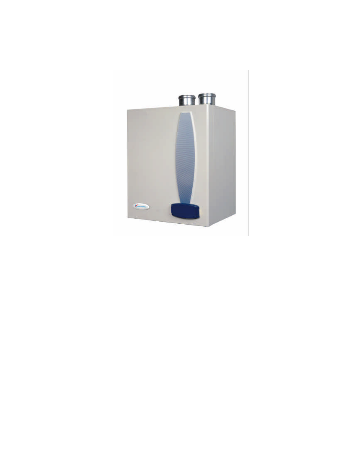
Mikrofill Ethos
Condensing combination boiler
Installation & Maintenance Instructions
30/36
42/46
Page 2

E &OE
Contents
1 SAFETY PROVISIONS.........................1
2 TECHNICAL DATA ..............................2
2.1 Drawing of front view.........................................2
2.2 Technical data.....................................................3
3 INTRODUCTION..................................4
3.1 Function..............................................................4
3.2 Control................................................................4
3.3 Products of combustion.......................................5
3.4 Modulating fan....................................................5
3.5 Multi speed pump................................................5
3.6 Discription ofappliance..........................................5
3.7 Combination models..............................................5
4 INSTALLATION....................................5
4.1 Contents..............................................................5
4.2 Siting the boiler ..................................................6
4.3 Mounting the boiler................................................7
4.4 Air inlet-flue gas outlet connection......................7
4.5 Inlet and outlet air system....................................9
4.6 Influence of exhaust removal on load...................9
4.7 Flue material...........................................................9
4.8 Flue resistance table..........................................10
4.9 Removal of condensation ..................................11
4.10 CH and hot water circulation.............................11
4.10.1 General....................................................11
4.10.2 Connecting the expansion vessel ..............11
4.10.3 Domestic hot water circuit........................11
4.10.4 Multi speed pump.......................................12
4.11 Frost protection................................................. 12
4.12 Connecting the gas supply................................. 12
5 ELECTRICAL INSTALLATION
INSTRUCTIONS................................. 13
5.1 Terminal board ..................................................13
5.2 Wiring diagram................................................. 15
6 COMMISSIONING ............................. 16
6.1 Control panel ....................................................16
6.1.1 Display.........................................................16
6.1.2 Keypad Control............................................16
6.2 Sensors .............................................................17
6.3 Installer's programme...................................... 19
6.4 Filling and venting boiler and CH installation....25
6.5 Initial Operation................................................27
6.5.1 General ........................................................27
6.5.2 Starting up for the first time..........................27
6.6 Adjusting and setting load.................................27
6.6.1 Setting maximum load .............................27
6.6.2 Setting minimum load..............................27
6.7 Conversion to another type of gas...................... 28
6.8 Hot water temperature.......................................28
6.9 Closing down....................................................31
7 Faults ...................................................32
7.1 Cause of faults........................... 34
7.2 Table of solutions..................................36
8 MAINTENANCE............................. ...39
9 USERS' INSTRUCTIONS................ ...41
10 EXPLODED VIEW DRAWING.......42
11 SPARES LIST......................................45
12 GUARANTEE...........................................46
Tables
Table 1, Technical data ...........................3
Table 2, Mikrofill resistance table.........10
Table 3, Hot water ................................11
Table 4, Programme numbers................20
Table 5, CH Water Content...................20
Table 6, Hot water ...............................21
Table 7, Faults ......................................32
Table 8, Other faults .............................33
Table 9, Rotational speed......................28
Table 10, Gas settings...........................28
Table 11, Minimum setting ...................28
Table 12, Maximum setting...................30
Table 13, Possible faults .......................34
Table 14, Fault Finding.........................36
Page 3

Installation manual MIKROFILL ETHOS
Page 1
1 SAFETY PROVISIONS
Conditions:
MIKROFILL shall not be held responsible for damage arising from inadequate compliance
with the installation instructions.
For service purposes, only original MIKROFILL spare parts should be used
General conditions:
All Mikrofill boilers must be installed by a competent person with regard to the relevant
requirements of the Health and Safety regulations, The Building Regulations, IEE
Regulations, Water Supply (Water Fittings) Regulations, Water Byelaws (Scotland), The Gas
(Installation and Use) Regulations and any local planning requirements.
1. UK Building regulation Part L1 (Domestic) Part L2 (Commercial) in which reference is
made to the following norms:
Directives for existing gas installations compiled by British Gas
2. IM16 Guidance notes on the installation of gas pipework
3. BS6644 Installation of gas fired hot water boilers ratedeinputs above 60kW but not greater
that 2 mW
4. Britisg Standards Code of Practice – BS6880 – Code of practice for low temperature hot
water heating
5. CP342 – Code of Practice part 2 – Centralised hot water supply
The Mikrofill ETHOS range of boilers are built in total compliance with EN
Page 4
Installation manual MIKROFILL ETHOS
Page 2
2 TECHNICAL DATA
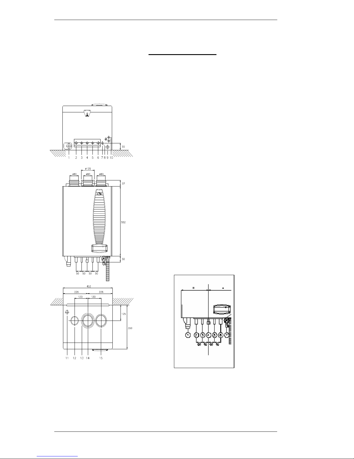
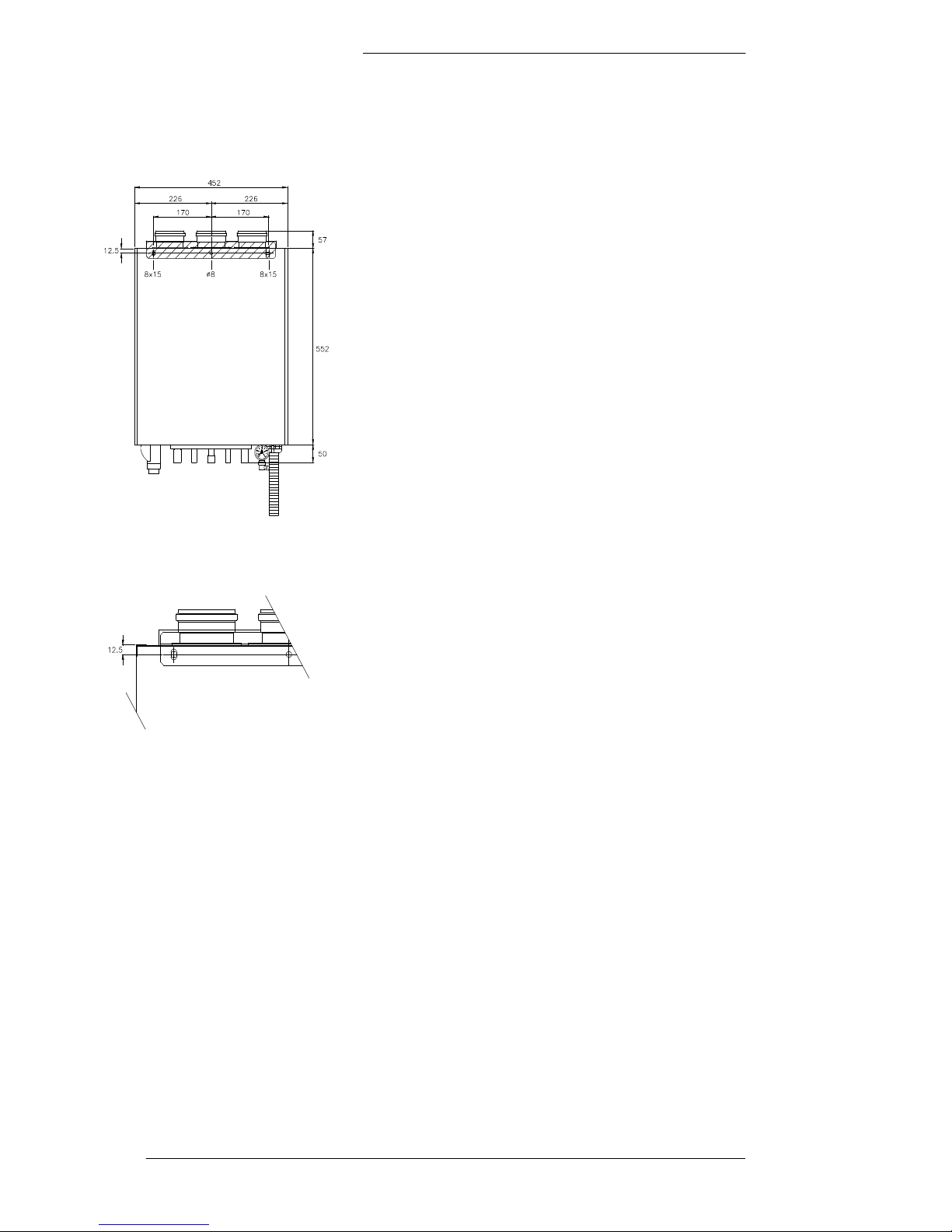
2.1 Drawing of front view
1 = Condense trap end cap
2 = CH flow (22mm)
3 = Domestic hot water (15mm)
4 = Gas
5 = Cold water inlet (15mm)
6 = CH return (22mm)
7 = Air Vent
8 = Manometer
9 = Condense drain outlet
10 = Cable entry
11 = Drain cock
12 = Air intake
13 = Air intake concentric
14 = Flue gas spigot
15 = Air inlet spigot
Page 5
Installation manual MIKROFILL ETHOS
Page 3
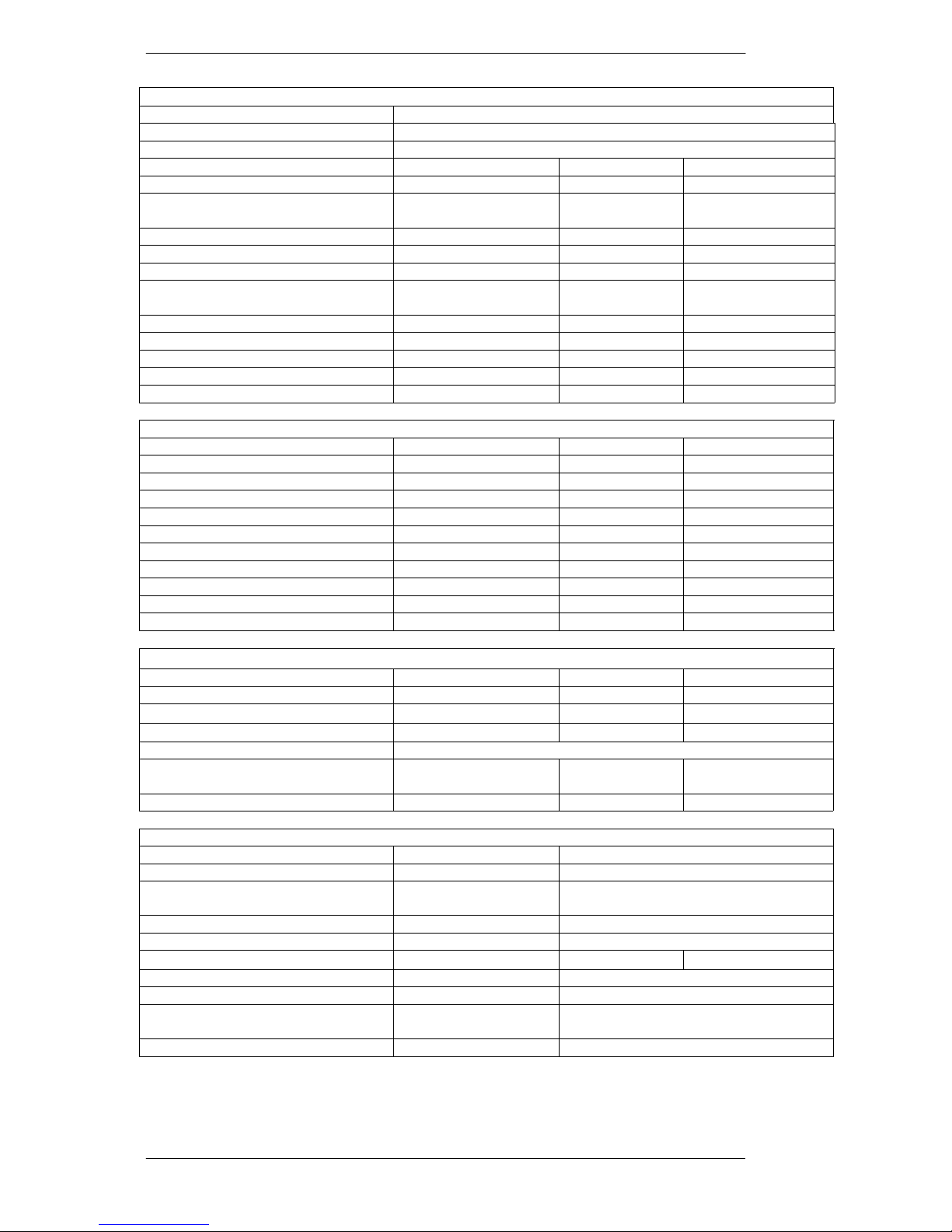
2.2 Technical data
Table 1, Technical data
General
CE Product ID number CE 0063 BL 3615- 2000
Dimensions (h x w x d) 550mm x 450mm x 350mm
Category II2L3P
Type of appliance Ethos
30/36 42/46
CH water content of appliance Litre 2,1 2,7
CH water content heat exchanger hot
water
Litre 1,5 1,5
Weight (empty) Kg 39 41
CH connections supply/return mm 22 22
Gas connection mm 15 15
Hot water, hot/cold mm 15
15
Flue gas connection mm 80 80
Air inlet mm 80 80
Concentric mm 80/125 80/125
Electrical power required kW 0.115 115
IP classification IP44 IP44
Capacity CH Operation
Nominal load (output) kW (min – max) 4.3 – 28.5 5.4 – 38.7
Nominal load (input) kW (min – max) 4.8 – 31.7 6.0 – 43
Max. gas use m³/hour 3.0 4.4
Efficiency at 50/30°C, full load % 106 106
Efficiency at 50/30°C, partial load % 109.5 109.5
Efficiency at 40/30°C, RAL 61 % 110 110
Nominal capacity at 80/60°C kW 4.1 – 27 5.3 – 38
Nominal capacity at 50/30°C kW 4.6 – 30 5.8 – 42
Gas approval HR Label 107 107
NOx emissions, RAL 61 mg/kWh <15 <15
CO emissions, RAL 61 mg/kWh <20 <20
Capacity Hot water
Nominal load (lower value) Kw 4.3 – 36 5.4 – 46
Nominal load (upper value) kW 4.8 – 40.0 6.0 – 51.0
Tap quantity at 60°C ( ?T=50K)
l/min 10 12.9
Tap quantity at 40°C ( ?T=30K)
l/min 17 21.4
WRAS Approval number 0204111
Annual use efficiency for EPC
calculation
% 83 82
Hot water (preset value) °C 60 60
Technical data
CO2 content flue gas % 9
Dew point of the flue gas °C 52
Temperature flue gas at 80/60 (with an
ambient temperature of 20 °C)
°C 75
Permitted resistance exhaust system* Pa Up to 100
PH value of the condensate 4 to 5.5
Available CH pump pressure kPa
15 at ?T20°C 28 at ?T25°C
Maximum supply temperature °C 90
Working pressure CH min/max. bar 1 / 3
Connection pressure sanitary water minmax
bar 0.2 - 10
NOx-class 6
Page 6
Installation manual MIKROFILL ETHOS
Page 4
3 INTRODUCTION
This manual is intended for the installer/user of the MIKROFILL range of
condensing boilers.This manual contains the necessary information relating to the
installation and settings of the Ethos 30/36 and 42/46.
You need to consult this manual before installation in order to ensure that you carry
out all the work correctly. In addition, it is advisable to keep this manual beside the
boiler, so it is immediately available if needed later.
3.1 Function of the appliance
High efficiency is achieved by means of a stainless steel heat exchanger, in which
the flue gases are cooled to below the condensation point, condense and release
further energy.
This is expressed in the efficiency exceeding 100%. The European method of
calculation assumes an efficiency of 100% for appliances in which provision is not
made for the condensation of flue gases and as a maximum efficiency of 110% in
condensing appliances.
In condensing boilers the flue gases are therefore at a low temperature (below
75°C), a stainless steel or thick-walled aluminium (1) HR [HE] approved flue
system or purpose designed plastic pipe needs to be used.
(1) When using an aluminium flue pipe, it is advisable to fit a condensation trap in
the flue system, to prevent pollution by aluminium corrosion.
The appliance is approved in accordance to all associated European norms (CE),
and the Netherlands requirements for Clean Air (SV), high efficiency (107% HR)
and the quality mark (Gas) as well as the quality mark for hot water (hot water class
CW) and as reheater for solar panels (NZ approval).
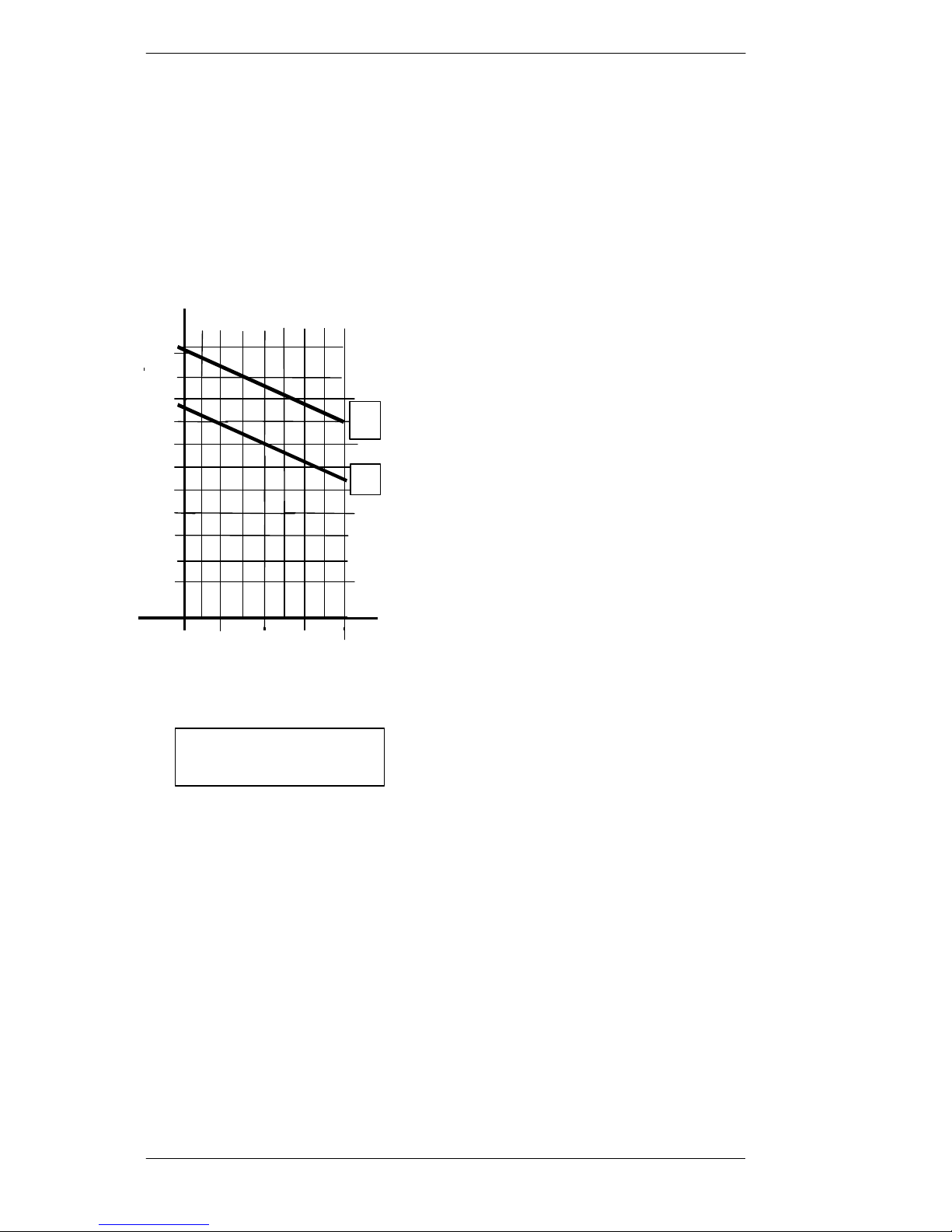
3.2 Control
The boiler can be controlled by way of a conventional
thermostat, or a modulating electronic room thermostat
(open therm), which can control the boiler output and
modulate between 12% and 100% of the total output of
the boiler.
The heat output is continuously adjustable ensuring that
the output of the boiler maintains a constant
temperature in the home irrespective of weather
conditions and provides hot water (combination boilers
only) at a constant temperature.
This variable heat output can also be achieved by
means of the built-in weather-compensation, by way
of an independent control or in conjunction with the
above thermostats. All forms of control can be used
with a conventional time clock.
MTC
15
16 17 18 19 20 21 22 23
ETHOS
20
30 90 20 10 0
-10
-20
Ambient temperature
°C 40 50 60 70 80
CH water temperature
°C
supply
return
Page 7

Installation manual MIKROFILL ETHOS
Page 5
3.3 Products of combustion
As a result of the variable combustion and the burner used, the results achieved for
combustion comply with the strictest norms in Europe. Sedbuk A Rated, Ultra low Nox, Ultra
low CO.
3.4 Modulating fan
An energy saving 24 volt high efficiency fan is used with variable speed and current use.The
fan revolves more slowly when the heat requirement is less, thus saving electricity.
3.5 Multi-speed pump
The appliance is fitted with a Grundfos pump (type UBS 15 – 60 HP) provided with a 3
speed switch for regulating the speed to enable the correct flow rate to be selected.
3.6 Description of appliance
The appliance is suitable for supplying a central heating installation. It has a variable
capacity between 12 and 100%.
3.7 Combination Models
These boilers have a built-in heat exchanger with a limited provision for hot water supply. All
connections are internal, while a built-in flow restrictor provides a maximum quantity of hot
water maintaining a hot water temperature of approximately 60°C.
The hot water is set at 60°C to prevent contamination with “Legionella” bacteria.
4 INSTALLATION
4.1 Contents
Installation & Users’ Manual
Vent key
Mounting bracket
2 spare fuses
3 spare burner plate nuts for fixing the burner plate (fixed on the front of the gas valve)
Strainer syphon with tightening nut and packing
Check the contents immediately on receipt.
Any damage must be reported to the supplier immediately.
Mikrofill appliances are completely assembled
Page 8

Installation manual MIKROFILL ETHOS
Page 6
4.2 Siting the boiler
:
Mikrofill appliances are suitable for all gas
groups G20.
The flue, whether single or concentric, must be
installed in compliance with the current flue
recommendations BS5440
Combination boilers should be sited as close as
possible to the hot water draw off point to avoid
excessive water wastage.
The installer will need to select and install an
expansion vessel which will be sized according to
performance requirements, along with a pressure
relief valve.
Page 9
Installation manual MIKROFILL ETHOS
Page 7
For maintenance and service purposes the front
and underside of the appliance need to be
accessible; both sides need to be at least 20mm
from a wall or cupboard wall.
The following need to be available in the room
where the appliance is to be mounted
a. 240v 1ph Electric.
b. A suitable drain for condensation water.
c. The wall on which the appliance is going to be
mounted must be capable of bearing the weight of the
appliance.
d. ETHOS boilers incorporate a modulating fan.
Although noise levels are minimal care should be
taken in siting the boiler to reduce disturbance from
noise.
4.3 Mounting the boiler
a. Using the mounting bracket, mark the holes for the
mounting plate and determine the position for
connection of the inlet and outlet pipes..
Warning! 1.
Make sure when you mark the position of the bracket
that it is level.
Warning! 2
The head of the fixing bolt, must not be more than 6
mm.
b. Secure the mounting bracket to the wall using screws
and plugs.
c. Mount the boiler.
4.4 Air inlet-flue gas outlet connection
General
There are 2 options of flue connection:
A.: separate air inlet and flue outlet;
B.: concentric connection (pipe in pipe)
A. Separate air inlet and flue outlet.
The optimum connection for air inlet and flue gas removal is achieved by using a corrosionresistant inlet system.
The dimension of the flue gas outlet pipe is 80 mm; the air inlet is similarly 80 mm.
The air inlet can be placed on either the left or right hand side of the flue gas outlet pipe.
?
Page 10
Installation manual MIKROFILL ETHOS
Page 8
B. Concentric connection , a set is available for a concentric connection: air inlet 125 mm and
flue gas outlet 80 mm diameter.
Always place the plastic inlet connection on top of the mouth of the air inlet pipe. This plastic
connecting piece prevents damage to the appliance if there is moisture present in the inlet pipe
The air inlet with an 80 mm diameter, must be closed with the seal supplied with it.
4.6(T)
1 = ETHOS 30/36
2 = ETHOS 42/46
kW
40 35 30 25 20 15 42
Load
100
200
300
400
500
( Pa )
Resistance
1
2
Page 11

Installation manual MIKROFILL ETHOS
Page 9
4.5 Air inlet and flue outlet system.
The MIKROFILL boiler is a room sealed appliance that does not use any oxygen from the
room in which it is installed; the casing is air tight, so that oxygen is provided only through
the air inlet pipe. The boiler must not be operated without the casing in place.
Note that horizontal parts need to have a gradient of 1% towards the boiler (1 cm per 1 m
length). If this is overlooked, condensation can collect in the flue gas outlet pipe which can
cause problems.
The resistance of the inlet and outlet system is 100 Pa in instances where the resistance is
greater than 100 Pa the maximum output of the boiler will be effected please refer to 4.6(T).
4.6 Influence of exhaust removal on load
The following table gives the ratio between the load and the resistance of the inlet and outlet
resistance of the system.
Up to a resistance of 100 Pa the load will remain near enough equal, with greater resistances
this changes with respect to the values on the type plate.
The resistance and change in the load influence only the maximum load and not the minimum
load.
Take account of possible load changes with hot water production and the transmission
calculation.
4.7 Flue material
The appliance must only be connected to systems manufactured from approved flue material
and must incorporate water tight seals to eliminate leakage of condensate.
To avoid exterior nuisance pluming (mist) we thoroughly recommend vertical flueing.
Page 12
Installation manual MIKROFILL ETHOS
Page 10
4.8 Flue resistance table
The load of the appliance is influenced by the resistance of the air inlet and outlet system
through the gas-air connection of the control of the appliance.
With a resistance up to 100 Pa., the load will be equivalent to what is shown on the type plate
of the appliance. The flue pipe induced draught is: 3 Pa/vertical metre.
Table 2, Flue resistance table
Example of calculation
Boiler type: 30/36 ETHOS
Air inlet pipe: diameter 80 mm; horizontal length: 5 m; vertical 25 m; 2 x 90° bend
Flue gas outlet pipe: diameter 80 mm; horizontal length 5 m; vertical 25 m; 2 x 90° bend
Concentric vertical flue terminal 80/125
Air inlet: Resistance
90° bend: 2 pieces 2 x 1.0 2.0 Pa
Straight pipe : 30 m. 30 x 0.8 24.0 Pa
Flue gas outlet
90° bend: 2 pieces 2 x 2.0 4.0 Pa
Straight pipe : 30 m. 30 x 2.0 60.0 Pa
Vertical terminal 4.5 Pa
94.5 Pa
Total resistance is now 94.5 Pa minus the vertical flue pipe induced draught of 3 Pa/vertical
metre therefore (25 x 3 Pa = 75) = 19.5 Pa (thus below 100 Pa); so that the capacity of the
boiler is not changed by the resistance.
Concentric Flue System (mm) Resistance inlet-outlet system
[Pa]
Part
ETHOS 30/36 ETHOS 42/46
Vertical Terminal 80/125 4.5 12.0
Horizontal Terminal 80/125 3.0 8.0
straight pipe/m 80/125 1.8 4.0
45° bend 80/125 0.9 2.0
90° bend 80/125 1.8 4.0
Two Pipe System (mm) Resistance inlet-outlet system
[Pa]
Air Inlet Part
ETHOS 30/36 ETHOS 42/46
straight pipe/m 80 0.8 2.2
45° bend 80 0.5 1.2
90° bend 80 1.0 2.0
Flue Gas Outlet
Vertical terminal 80 4.5 12.0
Horizontal terminal 80 3.0 8.0
straight pipe/m 80 2.0 4.0
45° bend 80 1.0 2.0
90° bend 80 2.0 4.0
Page 13

Installation manual MIKROFILL ETHOS
Page 11
4.9 Removal of condensation
The condensation outlet is on the underside of the appliance, on the right, and has a ¾”
diameter hose; place this flexible hose in the drain with an open connection .
Only use plastic parts for the condensation water outlet. Metal pipes are not permitted.
The appliance is provided with an in-built siphon, therefore the connection from the appliance
can be directly linked with the water supply in the house.
WARNING: blockage of this outlet can cause damage to the appliance. The guarantee for the
appliance does not cover any damage that arises in this way. In the correct situation the
condensation water flows away visibly, for example via a tundish.
The appliance is constructed in such a way that if the siphon becomes blocked the appliance
switches off before damage can occur to the burner.
4.10 Central heating and hot water circulation
4.10.1 General
If plastic pipes are used for supply and return, for radiators or under-floor heating, the pipes
should incorporate an oxygen diffusion barrier. In the absence of this barrier it is essential that
a Mikrofill air and dirt seperator or similar appliance is installed. This is good practice even
on steel/copper systems. This prevents contamination of the heat exchanger with system
debris and magnetite caused by oxidation of the pipework. The MIKROFILL guarantee may
be invalidated by failure to comply.
4.10.2 Connecting the expansion vessel.
Combination boilers
Combination boiler versions require an expansion vessel, safety relief valve and system
isolating valves. These can be supplied by Mikrofill.
System boilers
An expansion vessel needs to be fitted with a volume suited to the contents of the central
heating installation and static pressure; the expansion vessel is preferably fitted in the water
return pipework.
4.10.3 Domestic hot water circuit (Combination boilers only)
The boiler incorporates a domestic hot water flow control valve which must be adjusted
according to table 3 below.
Connect the cold water supply according to the current UK water regulations (April 2000); it
is advisable to fit a Mikrofill WRAS approved “quick fill loop” to enable recharging of the
boiler water system
Table 3, Hot water class
Appliance Setting HW class
ETHOS 30/36 10 l/min 5
ETHOS 42/46 12.9 l/min 6
Page 14

Installation manual MIKROFILL ETHOS
Page 12
To achieve a tap water temperature of 45°C or higher within 30 seconds, the hot water pipe
between the boiler and the outlet must be not more than approximately 20 metres long.
4.10.4 Multi speed pump
The pump has a multi speed regulator which is set at the highest level: in the models ETHOS
30/36, 42/46, setting II will usually be sufficient: Warning: Do not use level I, because the
flow rate will be insufficient.
The appliance has a built-in pump control with a delayed switch-off time of 3 minutes as
standard.
If more heat is demanded the pump will operate at maximum capacity; when the heat demand
ceases the pump will run for a further 3 minutes, and then stop.
Similarly the pump will run for 1 minute every 24 hours to reduce the possibility of the pump
seizing due to debris in the system.
This 24-hour period begins the moment that the electrical power to the appliance is switched
on.
4.11 Frost protection
The appliance has built-in frost protection, which activates the the central heating pump when
the water temperature in the boiler drops to 8°C.
At a boiler water temperature of 5°C, the burner ignites and burns until the feed temperature
reaches 10°C.
4.12 Connecting the gas supply
The gas supply must be suitable sized to ensure that there is no more than 1mbar of pressure
drop from the meter to the appliance, this is a mandatory requirement
Check the gas pipe for leaks. If an inert gas i.e. nirogen is to be used for the gas test,
precautions must be taken to ensure that the maximum pressure in the gas system is below
100mbar.
For the fitting of the gas pipe and valve only, to test for gas leaks, a pressure of 100 mbar is
briefly permitted.
Purge the gas pipe carefully, before the appliance is used for the first time.
Page 15
Installation manual MIKROFILL ETHOS
Page 13
5 ELECTRICAL INSTALLATION INSTRUCTIONS
Connection to mains voltage.
The appliance has an earthed mains plug. The appliance needs to be connected to an earthed
240v single phase supply. Minimum cross-section is 3 x 0.75 mm²; the electrical installation
must of course conform to the current regulations (see page 1).
A terminal board is provided for the further connections..
Care must be taken to ensure that the isolator for this mains cable is accessible at all times, so
that, for servicing for example, the appliance can be disconnected from the power supply.
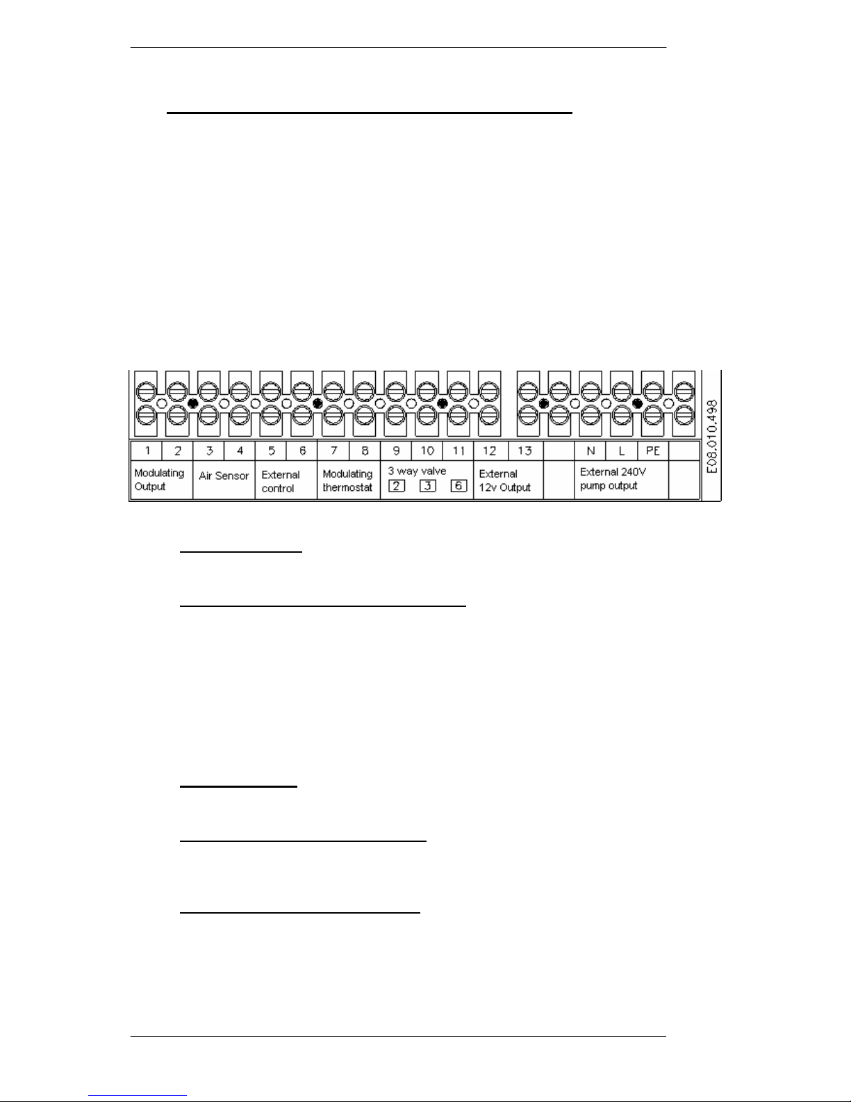
5.1 Terminal board
The following parts can be connected to the terminal connection board provided, see also the
diagram below:
1-2 PWM pump cable for the modulating signal for a modulating domestic or CH pump .
3-4. External sensor for weather compensation. If desired, the CH installation can be
regulated on the basis of the external temperature: if the external temperature drops,
the water temperature in the boiler is increased; the water temperature in the boiler is
therefore not subject to external influences such as the “sun” in the room, or an open
fire.
This regulation can be supplemented by a room thermostat.
If a room thermostat is not fitted, a wire loop needs to be fitted between terminals 5
and 6.
5-6. Room thermostat/ Time clock/BMS control can be connected here.
Maximum switch capacity is 2 VA.
7-8
Modulating thermostat (open therm)
Mikrofill has a series of modulating thermostats in its range, with which the boiler
modulation can be controlled.
9-10-11 External three-way valve - 24V only. If an external three-way valve is connected for
an indirect cylinder for instance, the three-way valve motor needs to be connected
here; in which case gate 9 is the neutral terminal, and terminals 10 and 11 are intended
for the 24 V AC Power open/Power closed.
These terminals can also be used for other 24V AC supply not exceeding 3VA
Page 16

Installation manual MIKROFILL ETHOS
Page 14
24 V AC For external regulation there is the option of having a 24 VAC power source;
terminals 10 and 11 can be used for this, with the limitation that:
a. remove the anticipation resistor (green) from the 4-gate terminal connection
board that is mounted on terminals 1 and 2.
b. maximum capacity must not exceed 3 VA.
12-13 If an external cylinder is connected, a sensor or a thermostat can be connected here.
If a sensor is connected, the boiler temperature can be read on the boiler display.
N-L-PE The 230VAC for an external pump is connected here; in combination with the PWM
signal this is connected to the terminals 1 and 2, or an internal modulating CH pump.
Temperature
Status
Service
Reset
--
+
Tap
Fault
Page 17

Installation manual MIKROFILL ETHOS
Page 15
5.2 Wiring Diagram
Page 18

Installation manual MIKROFILL ETHOS
Page 16
6. Commissioning
6.1Control panel
6.1.1. Display
Consists of two digits on the left hand side and one digit on the righthand side: left hand side
digits: feed water temperature of the boiler; right hand side digit: status of the boiler:
0 Stand by
1 Lock out fault/Control stop*
2 Flame proving/or ionisation fault
3 Fan pre-purge
4 Ignition
5 CH demand or timed overrun on CH pump
6 Domestic hot water demand
7 Circulating hot water heat exchanger or overrun on hot water pump
* With a longer period of “Control stop” may indicate shutdown on outside air
temperature. (Only if outside air control is fitted)
6.1.2. Keypad Control
The keypad provides access to various options for setting and controlling the appliance; this
always involves a combination of different buttons. The following combinations can be used:
1.Press “Service” and “Reset” simultaneously for 3 secs = Access to installation menu.
After these buttons have been pressed, the Status window will show “0”, while an “0”
will also appear in the temperature window. By means of the “+” and “-“ buttons in the
temperature display, the code with the value “8” needs to be set. After this press the
service button, to call up the various parameters.
If the appliance is functioning, a “-“ sign will be shown first, until combustion ceases,
after which the first parameter shows in the service window, and thereafter the various
parameters can be called up and adjusted.
Exit this installation menu by pressing the “Reset” button until the red LED above it goes
out, this stores the adjusted parameters automatically; if this is not required, the service
menu is exited automatically after a 1 minute delay, the amended data being stored.
1. Press “Service” and “+” simultaneously for 3 secs. = Gas valve set position, (an “h” is
shown in the display). By pressing the “+” or “-“ key, all the required number of
revolutions are set. The double display shows the number of revolutions in 100
revolutions (e.g. 35 means 3500 rpm).
Pressing “+” and “-“ keys simultaneously cancels setting the number of revolutions, and
the appliance functions automatically.
Page 19

Installation manual MIKROFILL ETHOS
Page 17
2. Press “Service” and ”-“ simultaneously for 3 secs. (=Faults). In this situation, an amended
software programme can be loaded or adjusted using a computer and the correct software
programme.
3. If the “TAP” button is pressed, the following data are displayed depending on the
situation:
-if water is not being drawn off: the heat maintaining temperature of the heating coil.
-when water is being drawn off: the hot water temperature.
6.2 Sensors
The following temperature sensors are fitted in the boiler:
S1 = flow sensor (vertical pipe on the front of the exchanger)
S2 = return sensor (on horizontal pipe between three-way valve and exchanger).
S3 = priority/heat maintenance sensor (sensor, on the right hand side of the heating coil).
S4= external temperature sensor (if fitted).
S5 = hot water (domestic) sensor (on 15 mm pipe, on the left hand side of the heating coil).
(Combination boilers only)
The sensors used are of the NTC (negative temperature control) type, and have the following
characteristics:
Sensor table
Temperature
[°C]
Resistance
Sensor 1, 2,
3, and 5
[Ohm]
Temperature
[°C]
Resistance
Sensor 4
[Ohm]
0 32550
-30 171800
5 25340
-25 129800
10 19870
-20 98930
15 15700
-15 76020
20 12490
-10 58880
25 10000
-5 45950
30 8059
0 36130
35 6535
5 28600
40 5330
10 22800
45 4372
15 18300
50 3605
20 14770
55 2989
25 12000
60 2490
30 9804
65 2084
35 8054
Page 20

Installation manual MIKROFILL ETHOS
Page 18
70 1753
40 6652
75 1481
45 5522
80 1256
85 1070
90 915
95 786
In addition the appliance has a high limit safety thermostat; this is mounted on the square
distribution pipe, on the right hand side of the stainless steel exchanger.
Page 21

Installation manual MIKROFILL ETHOS
Page 19
6.3. Installer’s programme
If the installer’s code is keyed in (after “Service” and “Reset” have been pressed for 3 secs.),
the following parameters can be set and adjusted (adjusted with the “+” and “-“ keys) , by
pressing the “service” button each time:
Programme
number
Name programme Adjustable between Factory setting
*0 Installer code 0 – 99 Installer code is 8
*1 Boiler type 0 = CH + coaxial coil
3 = CH + boiler with
own coil and external
three-way valve
0
*2 Pump action 0 = pump overrun
1 = pump continue
running
0
*3 Maximum CH capacity 19% and 99% 80%
*4 Maximum capacity during
drawing off
19% and 99% 99%
*5 Minimum supply temp. for
combustion line
10 … 25°C 20°C
*6 Minimum external temperature
for combustion line
-30°C…10°C -15°C
*7 Maximum external temperaure
for combustion line
15°C …30°C 20°C
*8 Pump overrun for CH function 1…15 min 3 min
*9 Pump overrun for HW function 0…90(0) sec. 6(0) sec = 1min.
*A OpenTherm Cascade 0 …99 kW 45 kW
*C Step modulation 0= step modulation ch is
not active
1= step modulation ch is
active; 5 minute steps
2= ditto, 10 min steps
3= ditto, 20 min steps
2
*d Regulating Central Heating 0 = room thermostat with
or without clock
1 = switch clock
0
*E Maximum supply temperature
CH function
18°C – 85°C 85°C
Exit this programme, after the parameters have been adjusted, by pressing the “Reset” key
until the Faults indicator light goes out.
Explanation of the set up options for the installer:
Programme number 1: Boiler type:
-For the normal combi boiler, key in the digit “0” here.
-if a boiler, with its own heating coil and an external three-way valve is used, programme in
“3”.
Page 22

Installation manual MIKROFILL ETHOS
Page 20
With respect to the three-way valve, a Honeywell three-way valve, type VC 80-10 needs to be
connected to the terminal strip, while the valve must be fitted in the circuit in such a way, that
the gate marked “B” is connected to the boiler circuit, gate “A” therefore on the CH circuit,
and on the “AB” gate on the CH boiler
Programme number 2: Pump action
Here it is possible to opt for the pump to over-run for the ch installation; this programming
has no influence on the over-run of the pump after drawing off: this over-run time is
established in parameter “9”.
For an over-run time for the CH installation, programme the digit “0”; the length of the overrun time is established under parameter “8”.
If continuous running is chosen (e.g. for underfloor heating), “1” needs to be programmed.
Programme number 3: Max. CH capacity (/revs of fan when CH functioning)
This allows the maximum CH capacity (40/30 °C) according to the type plate, to be reduced,
according to the accompanying table: CH functioning
Table 4, CH capacity
30/36
ETHOS
revs 42/46
ETHOS
revs
kW rpm kW rpm
100% 30.0 6250 42.0 6250
95% 26.6 5938 37.1 5938
90% 23.7 5625 32.8 5625
85%
21 5313 29.0 5313
80% 18.7 5000 25.6 5000
75% 16.6 4688 22.6 4688
70% 14.7 4375 20.0 4375
65% 13.1 4063 17.6 4063
60% 11.6 3750 15.6 3750
55% 10.3 3438 13.8 3438
50%
9.2 3125 12.2 3125
45%
8.1 2813 10.8 2813
40%
7.2 2500 9.5 2500
35%
6.4 2187 8.4 2187
30%
5.7 1875 7.4 1875
25%
5.1 1562 6.6 1562
19%
4.6 1188 5.8 1188
Page 23

Installation manual MIKROFILL ETHOS
Page 21
Combination boiler only
Programme number 4: Max. capacity during draw off ( revs of fan during HW function).
The revolutions of the fan during HW function are different from the revolutions during the
CH function, as the maximum load during draw off is higher.
The table for the load during draw off is shown below:
Table 5, Hot water capacity
36 ETHOS revs 46 ETHOS revs
kW rpm kW rpm
100%
36.0 7500 46.8 7500
95%
34.1 7110 45.4 7110
90%
32.3 6750 44.0 6750
85%
30.4 6350 42.2 6350
80%
26.6 6000 37.1 6000
75%
23.4 5550 32.4 5550
70%
20.4 5160 28.2 5160
65%
17.9 4800 24.5 4800
60%
14.7 4400 20.0 4400
55%
12.9 4000 17.3 4000
50%
11.2 3600 15.0 3600
45%
9.7 3200 12.9 3200
40%
8.1 2800 10.8 2800
35%
7.0 2400 9.2 2400
30%
6.0 2000 7.9 2000
25%
5.1 1675 6.6 1675
19%
4.6 1200 5.8 1200
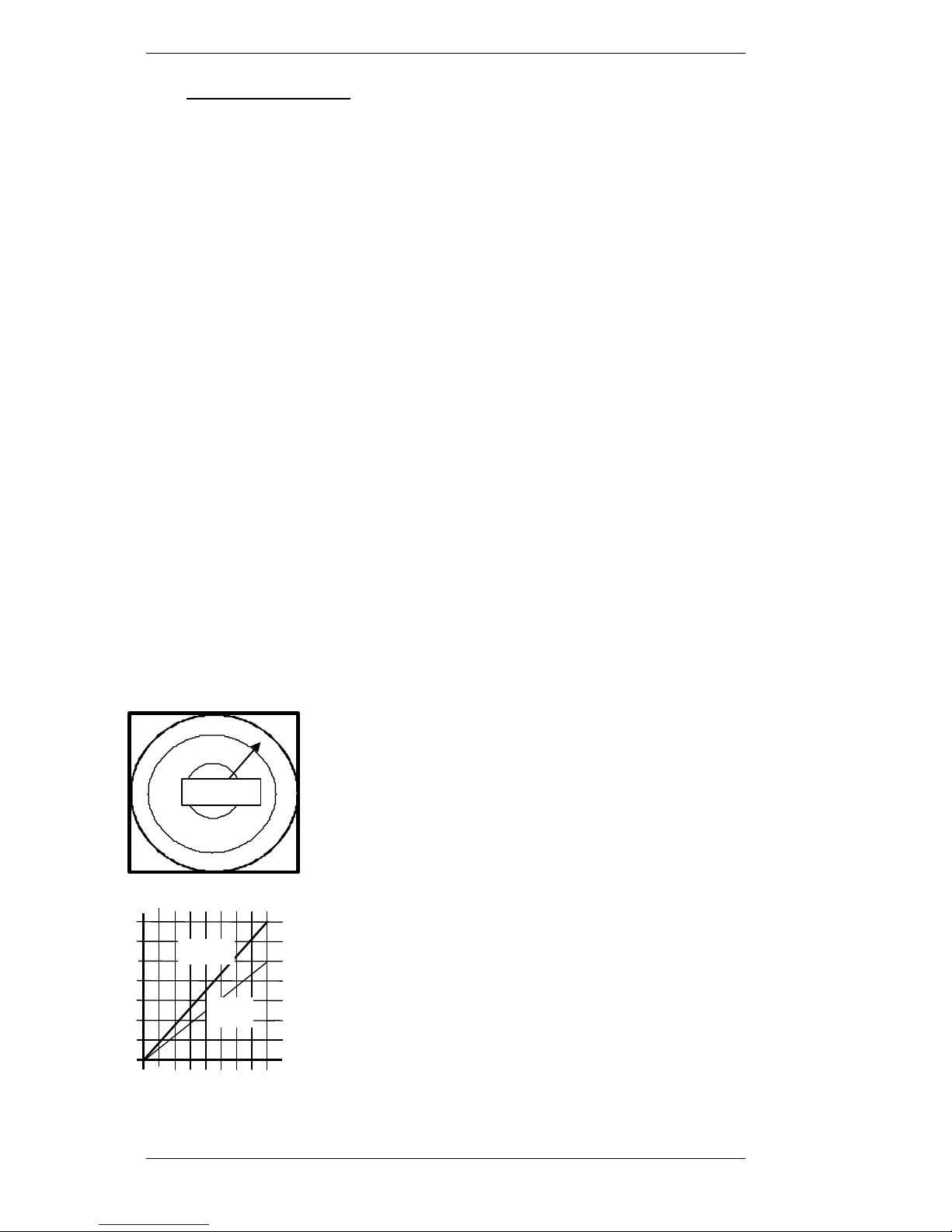
Programme number E, 5, 6 and 7
Setting combustion line
A combustion line is drawn between two points
that are determined by a specific external
temperature and the associated required feed
temperature of the CH water.
Instructions for determining this combustion line
are given in the steps below.
1st combustion line point at lowest external
temperature.
STEP 1. First of all the maximum feed
temperature (design temperature transmission
calculation) in the winter must be determined and
set; with the help of Programme number “E”,
enter this temperature (temperature chosen can be
between 18°C and 85°C). Choose e.g. 75°C.and
fix it by pressing the “Service” key.
20
30 40 50 60 70 80 90 °C
Exter
temperature °C
20 10
0
-10
-20
-30
30 10
Feed temperature
Page 24

Installation manual MIKROFILL ETHOS
Page 22
STEP 2. Now the associated external
temperature, by which this max. supply
temperature is required, needs to be
programmed in.
Press the “Service” key until it shows
Programme number 6.
Enter the external temperature here (e.g –
15°C, this is the temperature that is taken for
the transmission calculation).
In this way the first point of the combustion
line is established.
2nd combustion line point with a higher
external temperature.
STEP 3. Then the external temperature at
which no further heating is required needs to
be set e.g.15 °C external temperature.
Programme number 7 needs to be
programmed with this value.
STEP 4. As the last step, the supply
temperature needs to be set with the chosen
external temperature: this feed temperature
then needs to be the same as the external
temperature otherwise the appliance will not
switch off.
For this Programme number 5 needs to be
programmed, e.g. 15°C.
For buildings that are very solidly built (e.g.
castle walls), it will be necessary to allow the
appliance to continue burning for longer; in
such cases 30°C can, for example, be chosen
as the external temperature
This last programming step determines the
second point of the combustion line, and a
line is drawn automatically between these two
points.
As the accompanying drawing shows, at point
“1”, the combustion line will set an
increasingly high feed temperature even at
lower external temperatures, but the setting in
Programme "E” prevents this: the temperature
set is not exceeded.
At point “2”, the CH boiler will no longer be
burning
1
20
30 40 50 60 70 80 90 °C
Exter temperature °C
20 10
0
-10
-20
-30
30 10
Feed temperature
1
20
30 40 50 60 70 80 90
Exter temperature °C
20 10
0
-10
-20
-30
30 10
Feed temperature
°C
2
20
30 40 50 60 70 80 90
Exter temperature °C
20 10
0
-10
-20
-30
30 10
Feed temperature
°C
2
Page 25

Installation manual MIKROFILL ETHOS
Page 23
Programme number 8: Pump over-run time for CH function
This sets the over-run time of the pump after the demand for central heating ceases.
3 minutes is programmed by default.
Programme number 9: Pump over-run time for HW function
This sets the over-run time for the HW pump after the heating of the built in hot water
provision.
The setting can be between 0 and 900 seconds (15 minutes); the default is 60 seconds (1
minute): in the display the time is shown by omitting one 0.
Programme A: Open Therm Cascade
If more than one boiler is used for the central heating, the cascade manager function of an
Open Therm Control can be used to regulate these boilers (see the data from the suppliers of
the Open Therm controls).
In this case the maximum central heating load of each appliance connected needs to be
programmed in.
Programme C: Step modulation
This parameter enables the supply temperature to be increased in steps early in the morning as
the house is being warmed up, so that during this heating the appliance continues to condense
and thus is highly efficient. There are 6 steps to this programme, with a programmable
duration:
C 0 = no steps, thus on/off on the basis of the room thermostat
C 1= 6 steps each lasting 5 minutes
C 2= 6 steps each lasting 10 minutes (factory setting)
C 3= 6 steps each lasting 20 minutes
At each step the capacity is increased by 20%, beginning with the minimum capacity.
The boiler therefore starts with the minimum capacity, and this capacity increases every “5,
10 or 20” minutes, by 20%, until the maximum capacity is reached, or this programme
finishes, because the house has come up to temperature.
a. With an on/off room thermostat:
When there is no demand for heating, this programme counts back with the same time
intervals until there is a new demand for heating: the appliance then starts up with the
capacity appropriate to the time.
The efficiency of the boiler during the warming up period will always be greater than
100% and during the day will always have optimum output and avoid undesirable
fluctuations in the temperature of the house.
b. With an “Open Therm” thermostat
When the room temperature reaches the set value, the step programme is abandoned, and
the “Open Therm “ thermostat takes over the regulation of the boiler, and the capacity of
the boiler is adapted to the need for heat: the boiler will modulate optimally and the room
temperature will be kept very constant.
Page 26

Installation manual MIKROFILL ETHOS
Page 24
Programme d: CH Regulation
The controller is extremely flexible and will accept many types of external control. Almost
all controls imaginable for the CH installation can be connected or activated and will be
automatically detected by the automatic burner, there is however a difference between control
on the basis of a simple time switch and a normal room thermostat: if a time switch is used it
needs to be programmed in, under this Programme d.
An overview of the options for connection and the operation of it for the central heating
installation follows.
1. Simple day/night time switch with a daily or a weekly programme, in association
with the built-in external temperature control and the external temperature sensor.
*No room thermostat is used with this.
*Fitting each radiator with a thermostatic control valve is recommended.
*Connect the time clock to terminals 5 and 6 of the terminal board in the boiler .
*Connect the external sensor to terminals 3 and 4 of the terminal board in the boiler .
*If the time clock contact is closed (thus heat demand), the boiler supply temperature is
going to assume a value according to the combustion line set (see page 21 for setting the
combustion line,).
* If the time clock contact is open (night reduction), an automatic night reduction of 2.5°C
in the room temperature is achieved through a value programmed into the automatic
burner; this can be adjusted only by means of a special programme (call Mikrofill
Infodesk).
*With the next heat demand (e.g. the early morning warming up) the combustion line will
be increased by approximately 5°C for one hour (booster function), to bring the house up
to temperature quickly; the step programme does not need to be activated.
*Setting parameters: (bold type: need to be adjusted, the others remain unchanged
(factory settings): 1-0; 2-0; 3-80; 4-99; 5,6,7 and E are the combustion line settings; 8-3;
9-0; A-45; C-0; d-1.
2. An on/off room thermostat (or clock thermostat), in conjunction with the built-in
external temperature control in the boiler and the external temperature sensor.
*Connect room thermostat to terminals 5 and 6 of the terminal board in the boiler .
*Connect the external sensor to terminals 3 and 4 of the boiler terminal connection board.
*With this type of control, the room thermostat acts as a “safety net”: if it becomes too
warm in the room in which the thermostat is situated, the thermostat opens and the boiler
is switched off.: the pomp will run for 3 minute every 13 minutes, until there is a further
heat demand from the room thermostat; if the room thermostat cuts in too often the
combustion line needs to be lowered.
*The supply temperature is determined by the combustion line set.
*the night time reduction can be set by means of the room thermostat, or via the clock of a
clock thermostat.
*With the next demand for heat (e.g. the early morning warming up) the combustion line
with be raised by approximately 5°C for one hour (Booster function), to bring the house
up to temperature quickly; the step programme does not need to be activated.
*Setting parameters: (bold type, need to be adjusted, the others can remain unchanged
(factory settings ): 1-0; 2-0; 3-80; 4-99; 5,6,7 and E are the combustion line settings; 8-3;
9-0; A-45; C-0; d-0.
Page 27

Installation manual MIKROFILL ETHOS
Page 25
*If a separate time clock combined with an on/off room thermostat and the external
temperature control is used instead of a clock thermostat, it needs to be programmed in
accordance with 1.
3. An Open Therm clock thermostat in conjunction with the built-in external
temperature control in the boiler and the external temperature sensor.
*Connect the Open Therm thermostat to terminals 7 and 8 of the terminal board in the
boiler .
*Connect the external sensor to terminals 3 and 4 of the terminal board in the boiler.
*Except where adjustment is possible, no parameters need to be adjusted for the factoryset pre-programmed combustion line.
*Setting parameters: (bold type, need to be adjusted, the others can remain unchanged
(factory settings ): 1-0; 2-0; 3-80; 4-99; 5,6,7 and E are the combustion line settings; 8-3;
9-0; A-45; C-2; d-0.
4. Connect a room or clock thermostat to the boiler
*Connect the room thermostat to terminals 5 and 6 of the terminal board in the boiler .
*Except for where adjustment is possible, no parameters need to be adjusted for the
factory-set pre-programmed values.
*Setting parameters: (bold type, need to be adjusted, the others can remain unchanged
(factory settings ): 1-0; 2-0; 3-80; 4-99; 8-3; 9-0; A-45; C-2;
d-0; E-85
5. Connect an Open Therm (clock)thermostat to the boiler
*Connect the Open Therm thermostat to terminals 7 and 8 of the terminal board in the
boiler .
*Except where adjustment is possible, no parameters need to be adjusted for the factoryset pre-programmed combustion line.
*Setting parameters: (bold type, need to be adjusted, the others can remain unchanged
(factory settings ): 1-0; 2-0; 3-80; 4-99; 8-3; 9-0; A-45; C-2;
d-0; E-85.
Programme E: Maximum supply temp. central heating istallation.
This sets the maximum central heating temperature of the boiler.
6.4 Filling and venting the boiler and installation
Use the fill and drain tap in the central heating installation to fill the boiler and the
installation.
Page 28

Installation manual MIKROFILL ETHOS
Page 26
The correct fill pressure is 1.5 bar.
To prevent corrosion of the central heating installation, pay attention to the following points:
a. The filling water: do not add anything to the CH water, while the pH value needs to
be above 5 (if this is not the case you need to contact the supplier).
b. Flush system thoroughly
c. If plastic pipes are used, they need to be proof against oxygen diffusion in
accordance with DIN 4726/4729; if this is not the case, a separation needs to be
introduced between the boiler circuit and the circuit with the plastic piping.
d. Check for leaks in the circuit
Before starting the appliance for the first time the heat exchanger needs to be vented, once the
installation and the boiler have been filled. Open the vent valve, found on the upper left hand
side, a whole turn. As soon as water comes out of the vent cock, close the vent valve with the
key.
The boiler is provided with an automatic air vent on the top of the CH pump, which needs to
be open when the appliance is running; check that the cap is open at least one turn.
Check the fill pressure shortly after the appliance starts up, and if necessary add more water to
maintain the required pressure. The electronic control of the wall-mounted boiler has a startup programme, specially for venting the appliance. This programme is activated when the
mains power is switched on for the first time and after the “Reset” button is pressed.
This start-up programme runs for 2 minutes: for the 1st minute display code “7” is shown for
the 1st minute and code “5” for the 2nd.
Hot water circuit
The connections for hot and cold water are on the underside of the appliance.
Connect the pipes in accordance with the current regulations; fit an “inlet combination” in the
cold water supply pipe; which can be combined with the overflow pipe, with the condensation
waste pipe from the boiler.
The built-in limit valve needs to be set, with the appliance working; measure the quantity of
water at the furthest removed drain point and set the limiter according toTable 3, page 11.
Closing down
1. Isolate and disconnent the electrical system and turn off the gas tap.
2. If the appliance is switched off when there is a risk of frost, the CH boiler and installation
need to be drained; to do this open the fill and drain taps of the CH installation and the boiler
drain tap on the right hand underside of the appliance.
6.5 Initial Operation
6.5.1 General
The pre-pressure in the gas pipe can be measured with the test nipple (3) on the gas regulator .
The minimum pre-pressure which will allow the appliance to function correctly with the
correct load is 10 mbar.
Page 29

Installation manual MIKROFILL ETHOS
Page 27
6.5.2. Starting up the first time
When you have tested the installation and everything is in order, you can connect the
electrical system.
When the appliance is connected to the mains supply, the double display will show the supply
temperature and the single display the status of the appliance.
An automatic venting programme for the boiler lasting approximately 2 minutes follows the
mains connection.
The ETHOS appliance has a built-in provision for hot water.
Set the room thermostat at a high value so that the burner needs to ignite.
In an appliance with provision for hot water, the hot water will be heated up first.
There is a four-fold electronic start, followed by a faults warning on the status display. Next
press the RESET button for a return to the attempts to start.
To set the gas pressure, use screw [3].
6.6 Adjusting and setting load
To check the gas regulator or when attaching a new one, there are three methods for setting
the correct load:
A. By measuring the percentage of CO2
B. Check the gas consumption via the gas meter method.
C. By flame colour
Both the minimum and the maximum load need to be set using one of the three methods: the
maximum load needs to be set first, followed by the minimum load.
6.6.1 Setting the maximum load
Approximately a minute after ignition, press the keys marked “Service” and “+”
simutaneously; the double display shows the revolutions in hundreds, while the single display
shows “h” (CH). The number of revolutions of the fan can be increased or reduced by
pressing the “+” key or the “-“ key.
To obtain the maximum load press the “+“ key until the maximum number of revolutions is
reached.
If the measurement lasts for more than 10 minutes the appliance will return to automatic
operation; press the “Service” and “+” again to continue the measurement.
To return to the normal menu without having to wait for 10 minutes, press the “-“ and “+”
keys simultaneously.
Page 30

Installation manual MIKROFILL ETHOS
Page 28
Table 6, Revolutions
Appliance ETHOS
36
ETHOS
46
Minimum revs.
(rpm)
CH or HW
1200 1200
Maximum revs
(rpm)
7500 7500
Turn the setting screw for the maximum load if necessary [2], for the following method of
setting:
A. By measuring the percentage of CO2; this needs to be in accordance with the table below.
B. Check via the gas meter method.
C. By flame colour: until a blue colour with red points is achieved on the burner surface.
Table 7, Gas settings
Type of gas
Nat. gas G 25
LPG
Injector: none none
Mod. (bw)(MJ/m3) 41.52 76.64
Cal.value ow (MJ/m3)
29.25 88.00
CO2 max.load (%) 8.8(+/-0.3)* 10.5(+/-0.3)*
CO2 min.load (%) 8.6(+/-0.3)* 10.0(+/-0.3)*
* measured without cover
B. Gas meter method
Measured with natural gas or propane according to the table below:
Table 8, Setting the minimum [maximum?]
Note: For adjustment, the methods under B and C approach the correct adjustment: measuring
CO2 % is the preferred method.
To measure emissions, the measuring point in the heat exchanger can be used by unscrewing
the plastic cap.
Page 31

Installation manual MIKROFILL ETHOS
Page 29
WARNING !! When measuring do not put the probe more
than 2 cm into the heat exchanger to avoid deviations in the
result.
6.6.2 Setting the minimum load
After setting the maximum load press the “-” key until the
minimum revolutions are reached (11 to 12 on the display).
To set or adjust this minimum load, turn screw [1] for the
minimum setting.
Appliance 30/36 42/46
Natural
gas
50 litres in 42
sec.
50 litres in 34
sec.
LPG 15 litres in 38
sec.
15 litres in 30
sec.
Appliance 30/36
ETHOS
42/46
ETHOS
Natural
gas
5 litres in
32 sec.
5 litres in
20 sec.
LPG 2 litres in
39 sec.
2 litres in
31 sec.
Page 32

Installation manual MIKROFILL ETHOS
Page 30
The CO2 % is reduced if the screw is turned anti-clockwise and increased when it is turned
clockwise.
A. Setting on the basis of the flame colour.
The flame colour needs to be red/orange.
B. Gas meter method.
Minimum load according to the table below:
Table 9, Setting the maximum [ minimum?]
values measured with a boiler water temperature of approximately 60°C.
Press the “-“ and “+” keys simultaneously, which returns the appliance to automatic function;
the set-up programme is interrupted in any case after 10 minutes and the appliance returns to
automatic function.
6.7 Conversion to another type of gas
If the appliance is set up for LPG the following steps need to be taken.
a. The white gas-air mixing chamber is situated on the side of the fan. This mixing chamber
has one or two air inlet ports, at the front and in the case of a second opening, also at the
back, depending on the type of boiler. These ports need to be closed for conversion to
butane/propane.
Mikrofill can supply the correct stoppers on request:
ETHOS 32/36 one stop 15 mm
ETHOS 42/46 one stop 15 mm
b. Turn the screw [2] 4 whole turns (clockwise).
Set the appliance running; if the burner has not ignited after 4 attempts, turn the screw [2] one
turn back (anti-clockwise).
c. If the burner has ignited: press the keys marked “Service” and “+” simultaneously for
approximately a minute after the ignition
d. Display shows the revolutions in hundreds, while the single display shows “h” (CH). By
then pressing the “+” key, or the “-“ key, the number of revolutions of the fan can be
increased or decreased.
e. For the maximum load press the “+“ key, until the maximum number of revolutions is
shown (75 in the display).
For setting the maximum and minimum burner load, follow the information under paragraphs
Error! Reference source not found. and Error! Reference source not found., with
associated tables.
6.8 Hot water temperature
This is set by the manufacturer at 60°C to avoid danger from “Legionella” bacteria at lower
temperatures.
Page 33

Installation manual MIKROFILL ETHOS
Page 31
This value cannot be adjusted.
6.9 Closing down
It is advisable to keep the appliance switched on winter and summer. This prevents the
appliance freezing and moving parts seizing up due to corrosion.
Switch off the appliance by reducing the setting of the room thermostat: this will ensure
minimum power consumption, as the CH pump and fan stop running after a short time.
If the appliance does need to be closed down, the following precautions need to be taken:
a. Close the gas valve
b. Disconnect mains electric
c. If there is a risk of frost drain the appliance and the installation.
To drain down the boiler, isolate the boiler from the heating system or drain the heating
system. Attach a suitably sized hose to the drain valve on the boiler and open drain valve.
For the domestic water supply part, the inlet combination stopcock needs to be closed and a hot
water tap opened.
Page 34

Installation manual MIKROFILL ETHOS
Page 32
7. Faults
In the unlikely event that the appliance develops a fault, it can be set to run again simply by
pressing the “Reset” button.
The following faults can occur, in which the digit below flashes in the single Status display
and a code appears in the two digit display.
You will find the solution to the faults in Table 12 on page 34 and Table 13 on page 36
Table 10, Faults
Flashing faults
text in the
single display
Two digit
display
code:
Description of the fault: Cause of the fault
(see page 34)
no indication none Fault with electrical supply 14;50
no indication none Fan runs continually 49
0 Maximum thermostat open 4;5;21;23;24;29;30,42,46
0 Glass fuse F5 defective 15
0 F1 Short circuit feed sensor (S1) 3;41;42;43
0 F2 Short circuit return sensor (S2) 3;41;42;43
0 F5 Short circuit HWsensor (S5) 3;41;42;43
0 1 Lack of feed sensor (S1) 41;42;43
0 2 Lack of return sensor (S2) 41;42;43
0 5 Lack of HW sensor (S5) 41;42;43
1 E1 Temp. feed sensor too high (S1) 4;5;23;29;46
1 E2 Temp. feed sensor too high (S2) 4;5;23;29;46
1 E3 Temp. priority sensor too high (S3) 24;45;46;51
1 E5 Temp. HW sensor too high (S5) 24;45;46;51
2 5 Feed and return sensor exchanged
2 21 Feed temp. lower than return temperature,
during running.
4;21;23;24;29;47
2 E Feed and return temp. unequal during stand
by
23;43
3 Supply temperature rises too quickly 4;5;21;24;28;29;46;51
4
No flame after 4 ignition attempts 10;11;16;18;22;25;35;48
5 Flame decreases while running 11;12;16;22;26;44
6 Flame signal during stand by 18;35;61
7 Appliance is programmed 62
8,9,A Fan revs incorrect 7;8;9;13;19;39;40;41
B One or more parameters are incorrect 63
C Gas valve or gas valve circuit is not correct 17;20;30;34;36;37
D Check on gas valve reg. shows fault 17;20;30;34;37
E Check on the mains voltage 64
F Software fault; EMC external radiation 34
H Reset button hanging or is defective; if the
“H” does not flash: memory defective.
65
Fuse F 1: for ignition 63 mA;
Fuse F 2: for regulation 630 mA;
Fuse F 3: 35 VAC 3.15 A; for fan
Fuse F4: 230 VAC 3.15 A; for mains voltage
Fuse F 5: 24 VAC 1 A, for three-way valve
All fuses are of type: Anti-surge
F4
F3
Trans
F1
Page 35

Installation manual MIKROFILL ETHOS
Page 33
In addition there are also a number of faults that cannot be shown on the display.
A number of these faults or symptoms are shown below:
Table 11, Other faults
Symptom
Cause of fault (see p34)
a House does not reach temperature, appliance firing 45;53;54
b Ignition is loud 35
c Boiler burns continuously but CH water does not warm
up
45
d Room thermostat demands heat, but boiler does not
ignite
1;42;52
e Boiler burning continuously, house too warm 2
f Boiler very noisy when CH working 29;46
g Radiators not hot enough at the top 55
h Water drawn off but water from the hot tap remains
cold
24;56
i Hot water much too hot 51;57
j Water is drawn off, but the water from the hot tap does
not reach 60°C
51;58
k Boiler very noisy during HW operation 23;59
l Fault after replacement of automatic burner 60
Page 36

Installation manual MIKROFILL ETHOS
Page 34
7.1 Causes of faults
The following causes can account for the faults on pages 32/33.
Table 12, Causes of faults
1. Room thermostat is incorrectly connected.
2. Room thermostat does not switch off, short circuit in the cable.
3. Sensor makes a short circuit in the cabl
e or internally.
4. Pump does not run; stuck
5. Water pressure in the CH installation is too low.
6. Water pressure in the CH installation is too high.
7. Fan is not connected (forgotten to connect plug).
8. Fan is dirty.
9. Fan is defective.
10. Valve
is not open.
11. Gas pressure is too low.
12. Incorrect pipe size
13. Fuse F3 defective
14. Fuse F4 defective.
15. Fuse F5 defective.
16. Gas valve setting at the lowest revs. is not correct.
17. Gas valve is not connected or incorr
ectly connected electronically.
18. Ignition cable not correctly connected.
19. Transformer defective.
20. Connection plug to gas valve incorrectly connected, or moisture in the surround
21. Pump plug incorrectly connected.
22. Siphon blocked.
23. Hand bleeder opens and closes after bleeding.
24. Three
-
way valve is dirty.
25. Too much resistance in the supply system or supply system dirty.
26. Exhaust system leaks to supply system; recirculation flue gas, only with
conc. connection.
27. Supply system lets in water.
28. Through flow setting tap is dirty.
29. Heat exchanger is blocked (insufficient circulation)
30. Maximum thermostat defective (insufficient circulation)
31. Maximum load too high.
34. Auto
matic burner defective.
35. Ignition electrode defective (porcelain cracked), gap to burner is incorrect
36. Moisture on the cables of the gas valve.
37. Moisture on printed circuit board of the automatic burner.
38. Moisture in the pump wiring.
39. Moisture on fan and/or connection.
40. Fan plug connected incorrectly.
41. Plug incorrectly connected.
42. Connection cable damaged.
43. Sensor defective.
44. Flue gas circulation behind from the heat exchanger.
45
Hot water drain tap leaking
Page 37

Installation manual MIKROFILL ETHOS
Page 35
46 Position of the revolution switch on the pump is set too low
47 Sensors interchanged (return sensor S2 and hot water sensor S5)
48 Fuse F1
49
Fuse F2
50
Mains voltage 230 VAC
51
Parameter(s) in the installers programme entered incorrectly
52
Open Therm room thermostat, or normal thermostat on an incorrect terminal board gate
53
Step programme in the installers menu not correctly programmed; or steps too long
54 Clock programme of the clock thermostat needs to start earlier in the morning
55 Supply and return pipe interchanged on the appliance
56
Cable or plug to three
-
way valve incorrectly connected
57
Preference sensor (S3) is incorrectly placed or is defective.
58
The through flow setting tap in the cold water pipe needs to be adjusted
. 59 Coil exchange for hot water needs to be descaled
60
Cable loom plugs on the printed circuit board incorrectly fitted
61
Gas regulator defective
62
After programming with a computer, confirmation of new settings
63 Incorrect parameters, or a value outside the scope of the programme, have been
programmed
64 The automatic burner carries out a frequent check on the supply voltage
65 Mechanical defect with the Reset button with a flashing “H”; with a steady H, there is a
defect in the automatic burner.
Page 38

Installation manual MIKROFILL ETHOS
Page 36
7.2 Table of solutions
Numbers correspond to Table 12
Table 13, Table of solutions
1. Check cable or replace cable, check if it is connected to the correct terminal board.
2. Replace room thermostat or replace cable: is the correct thermostat fitted.
3. Replace sensor or trace fault in cable.
4. Try to free the pump shaft or replace the the driving part of the pump.
5. Top up water and trace the leak, also check the expansion vessel for internal leaks.
6. Too much topped up or check pressure of expansion vessel or replace expansion vessel.
7. Insert plug: plug part with cables is on the side of the fan.
8. Clean the blades of the fan.
9. Replace the fan.
10. Open the gas tap.
11. Check the pipe and gas meter, possibly calculate resistance.
12. Replace gas pipe.
13. Replace fuses; F3 fan check: moisture, short circuit, plug, wiring
14. Replace fuses; F4 check all 230 V connections: pump, circuit board connection
15. Replace fuses; F5 check the connection, the plug and the motor for the three-way valve
16. See paragraph 6.4
17. Check the cabling using the wiring diagram, check the connection to the gas valve, check for
moisture.
18. Check cable for short circuit, overheating close by or pinched between steel plate; check the
spark plug cap for cracks, replace the cap.
19. Replace the automatic burner.
20. Moisture inclusion, check on the cable sockets which need to be plugged in correctly to the
electric plug, check the position of the cable sockets, possibly straighten, before the plug is
put in.
21. Check whether the plug(s) fit(s) correctly in each other, with the correct press-on force.
22. Open the flush pipe (left side of the appliance), by unscrewing the cap: hold a jar under it, to
catch the water that runs out. Poke out this pipe with a thin rod, to both upper left and upper
right. If necessary remove the burner unit from the appliance, and pour water into the heat
exchanger to rinse out the siphon.
23. Venting, not simply the boiler but the whole installation – with this complete venting, the
230 V plug of the appliance can be removed from the socket, as the CH does not need to
function during bleeding.
24. Inspect the shut-off valve of the three-way valve, by removing the pump motor by
unscrewing the four fixing screws; the valve can be inspected on the inside of the housing.
The drive motor can be removed, by removing the fixing screw on the front of the housing
(below right), and then pressing in the “snap” lip, situated on the side of the housing, just
above the motor, and at the same time pushing the motor downwards.
25. Check the feed-discharge pipe for blockages.
26. Check the feed-discharge system.
27. See 26.
28. Take off the cold water connection from the appliance and remove and clean the through
flow setting cock.
Page 39

Installation manual MIKROFILL ETHOS
Page 37
29. It is advisable to remove the automatic burner from the appliance first, to avoid water
damage to the printed circuit board.
After the appliance has been drained, the coupling of the T-piece in the supply pipe, and the
flat coupling of the return should be loosened near the pump.
Detach the earth and the spark plug cables, and the wires of the maximum thermostat (above
right).
After this detach the three tension bars, push the heat exchanger partially forward, and
detach the electrical plug on the fan; then remove the exchanger from the appliance.
30. Replace the maximum thermostat by unscrewing it from the brass nut: the system does not
need to be drained (do not remove the brass nut).
31. Follow the setting up procedure in paragraph 6.4.1.
34. Remove the automatic burner with housing from the appliance by:
a. Removing the lid
b. Remove the wiring on the printed circuit board –1 x 2 pin connector (back of printed
circuit, with green wires), 1 x 8 pin connector (front left), 2 x 16 pin connector, and the
230V plug (righthand side).
Remove two screws on the underside securing the housing, then the housing including the
automatic burner can be removed from the appliance.
Next remove the small display cable from the printed circuit board, push the automatic
burner out of the housing and replace it.
35. Replace or bend. warning: bend close to the burner plate, otherwise it could break.
36. Dry off, possibly blow dry with warm air (hairdryer) and check that it functions correctly,
Replace if necessary.
37. See 36.
38. See 36. Remove the connection and dry it; possibly by blowing or blow dry with a hairdryer.
39. See 36. Remove the connection and dry it; possibly by blowing or b low dry with a hairdryer.
40. Plug wire connection needs to point to the exterior of the fan and to drop with one side in the
slot of the printed circuit board.
41. Check the plugs and push them into each other correctly.
42. Check cables for possible damage or kinking and replace if necessary.
43. Check pipe connections, replace sensor.
44. Check the connection of the heat exchanger on the flue gas box, if necessary re-fit, fit new
lip ring.
45 Check all draw-off points, and possibly HW pipes for leaks.
46 Set the switch for the pump to position 3.
47 There is a sticker on the pipe indicating the colour of the sensor cabling.
48 Possibly replace the fuse (must be a reason for the defect); there is no spare fuse, see
diagram on p.22.[?]
49 Possibly replace the fuse (must be a reason for the defect); there is no spare fuse, see
diagram on p.22. [?]
50 Check the mains cable, the wall socket box for voltage; main fuse.
51 Check the programmed parameters on p.18
52 Check the type of room thermostat, and the sticker with the indication on the terminal
connection board on the appliance.
Page 40

Installation manual MIKROFILL ETHOS
Page 38
53 Adjust the step programme, see pp. 18 and 21.
54 Introduce an adjustment in the times for “rising”, in the clock thermostat.
55 Supply (water leaving) is on the left hand side of the appliance return on the right.
56 Push the 4-core cable with miniplug into the three-way valve motor; check the three cables
(2 x red and 1 x yellow) in the terminal connection board gate 9, on the cover, remove and
re-fit.
57 Check the correct fitting of this in-feed sensor in the immersion sleeve.
58 Set with an Allen key of the correct size (8 mm).
59 The appliance needs to be drained on both the CH side and the HW side.
The drain spiral can be taken out of the appliance if the two T pieces on each side of the
spiral are removed with the aid of the flat couplings.
Remove the fixing bracket on the underside of the spiral.
The space between the inner and outer tubes is rinsed with water from the domestic system
and may be furred up or dirty; this part needs to be washed through.
60 It is possible that one pin has been shifted too far in the 18-pin printed circuit board
connector so that the wiring does not connect with the correct pins: check both the left and
right hand sides of the printed circuit board to ascertain whether or not the connector(s) is/are
correctly fitted.
61 There are usually two reasons for a defective gas regulator: the electric coils are defective or
there is an internal fault in the gas valve; in either case it is advisable to replace the whole
gas tap.
62 If the boiler control can be adjusted using the“service software” and the adjusted parameters
are programmed, this is the confirmation that the boiler control has accepted the new
parameters.
63 The correct software (please check this) must be used for programming, at the same time the
threshold values must not be exceeded; try to programme again.
64 The supply voltage needs to be checked with a universal meter; if the supply voltage is
correct (it needs to be between 190 and 250 Volt) the automatic burner needs to be replaced.
65 In order to repair the Reset button, the display can be removed from the plastic spacers and
can once again be checked for correct functioning: if negative, the display needs to be
replaced; if the display functions outside the appliance, you need to check whether the button
has sufficient space under the the plastic cover (is it jammed?); loosen it.
If the “H” does not flash the automatic burner needs to be replaced.
Page 41

Installation manual MIKROFILL ETHOS
Page 39
8 MAINTENANCE
General maintenance / inspection needs at least every 12 months or sooner if the appliance is
not working correctly or the boiler control generates the same fault codes a number of times.
Inspection:
The following operations need to be carried out for inspection.
a. Ask the user about possible problems with the CH appliance and/or any other
problems.
b. Check the installation (water) pressure.
c. Remove the cover of the appliance and inspect all pipes and connections for traces of
water and/or water leaks.
d. Inspect the upper side of the cover and upper side of the appliance for signs of water
or leaks from the air inlet pipe or the venter.
e. Open the siphon, and remove any dirt.
f. If a laptop is available, connect it and check the service page about the reports of
faults, starts and failed/successful attempts at starting.
g. Set the appliance to maximum combustion and measure the load and CO2 % when
operating.
h. Set the appliance to minimum combustion and measure the load and CO2 % when
operating.
i. Note the noise of the CH pump and the fan.
j. For an ETHOS boiler, measure the quantity of hot water and the hot water temperature
with the hot water tap fully opened.
k. While the hot water is warming up, check that the supply to the CH installation does
not become warm.
l. Dismantle the burner unit by removing the 6 M6 nuts, disconnecting the ignition cable
and pulling the burner unit forward.
If the burner is pulled halfway along the furnace, the plug needs to be removed from
the fan cable.
Check the inside of the heat exchanger.
m. Dismantle the plastic air inlet box on the inlet side of the fan, inspect the fan blades.
n. Check the distance between the electrode and burner; this gap needs to be 4 to 5 mm.
4 to 5 mm
4 to 5 mm
Burner
Page 42

Installation manual MIKROFILL ETHOS
Page 40
Maintenance:
Depending on the result of the inspection, the maintenance should be preventative as far as
possible.
The reason for this is:
re a. The comments and remarks of the client need to be taken seriously and the causes need
to be found for any faults and problems.
re b. Pressure of the installation needs to be brought up to between 1 and 2 bar: any leaks in
the installation need to be traced; possibly rectified by installer or service department.
re c. Any leaks need to be rectified.
re d. If water is leaking from the air inlet pipe the cause must be traced; it may be in the roof
or in a concentric pipe, through leakage from the flue gas exhaust pipe.
re e. If the condensation water from the siphon is very dirty this needs to be rinsed out; there
are a number of options for this :
1. If the burner has already been removed, fill the water pipe in the heat exchanger,
which will reach the siphon automatically.
2. Push the supply pipe up (if possible) so that water can be added to the supply of the
appliance.
re f. Select conclusion from the service screen and note the parts that are the cause of these
faults using the service programme and a laptop.
re g. See h.
re h. If necessary adjust the gas setting to minimum load on the gas valve.
re i. If the CH pump is noisy, and especially if it is more than 5 years old, replacement of the
pump motor is recommended as a precaution.
re j. With a hot water quantity less than the value in Table 3 (page 11), the water flow
regulator needs to be checked for dirt. If this is clean, and the hot water quantity shows a
value less than Table 3 (page 11), the heat exchanger for the hot water needs to be de-scaled
or replaced, as it is 99% likely that limescale deposited in the domestic exchanger is the
cause.
re k. If the supply water increases in temperature during draw off, it means that the three-way
valve is dirty on the inside and this needs to be cleaned or replaced.
re l. The burner itself must never be cleaned. If the heat exchanger is dirty on the inside and/or
there are deposits on the inside from the stainless steel pipe, this needs to be removed with
citric acid or a stiff brush (do not use a wire brush!).
Then remove the dust with a vacuum cleaner.
re m. If the blades of the fan have deposits of dirt, each blade needs to be cleaned carefully
until the material of the blade is visible. If this is not done evenly the fan will not run evenly
and an imbalance will occur.
re n. Carefully adjust the electrode, without bending the burner, until the correct gap is
achieved. (see page 29)
Page 43

Installation manual MIKROFILL ETHOS
Page 41
9 USERS INSTRUCTIONS
Brief the user how to operate the whole installation. In particular make sure the user is
familiar with the safety provisions.
Tell the user that the boiler needs to undergo inspection and maintenance every 12 months.
Regular servicing is needed for the boiler to function safely.
Hand over the paperwork supplied with the boiler to the user.
Page 44

Installation manual MIKROFILL ETHOS
Page 42
10 EXPLODED VIEW DRAWING
1-5-2000
Burner+fan+gas pipe
Page 45

Installation manual MIKROFILL ETHOS
Page 43
Cladding+electronics
Page 46

Installation manual MIKROFILL ETHOS
Page 44
Pipes+pump+coaxial coil
Page 47

Installation manual MIKROFILL ETHOS
Page 45
11 LIST OF SPARE PARTS
Po
s
nr.
Name Orderno.
1 Cover air inlet 80 mm 545-2020
2 Air inlet pipe mouth 125 mm 5453 Packing pipe mouth 125 mm 5454 Side panel+insulation 5455 Front panel+front
valve+insolation
545-
6 2x Hinge+Front valve 545-2012
7 Front valve 545-2011
9 Display+ribbon cable 545-2051
10 Cover with cable harness
complete
545-
11 Boiler control (automatic
burner)
545-2060
12 Pipe entry 54513 Mounting bracket 54514 Packing air inlet 80 mm 545-2025
15 Air inlet pipe mouth, 80 mm 54516 Seal 125 mm to 80 mm 54517 Pipe mouth flue gas outlet 54518 Packing flue gas outlet 54519 Siphon inlet with hose zie 20
20 Siphon complete 54521 Fluegas collecting chamber 54522 Tension frame 545-2013
23 Lip ring flue gas chamber 545-2080
24 Bleeder 1/8” 545-2090
25 Maximum thermostat 545-2052
26
Heat exchanger 30/36
ETHOS
545-
545 Heat exchanger 42/46
ETHOS
545-
27 Cap gauge point+packing 545-2021
28
28 Burner bar 30/36 ETHOS 54528
28 Burner bar 42/46 ETHOS 54529 Packing burner 545-2081
30 Insulation burner plate 54531 Nut M6 burner plate 54532 Packing electrode 545-
33 Electrode 30/36 t/m 42/46 545-2009
34 Spark plug cover 545-2053
35 Packing gas/air channel
30/36; 42/46 ETHOS
545-
35
Packing gas/air channel
30/36 ETHOS (red)
545-
36 54536 Gas/air mix chamber 30/36 54536 54536 Gas/air mix chamber42/46 54537 “O” ring mixing chamber 54538 Fan 545-2054
39 Gas pipe lower 54540 Packing gas pipe (NBR) 54541 Gas valve 545-2055
42 Gas pipe upper 54543 Strainer siphon, with seal zie 20
44 Flex hose siphon outlet zie 20
45 Entry socket 25 mm 545-2021
46 “O”ring 4 mm 54547 Return sensor 18 mm 545-2056
48 Giannoni “O” ring 54549 Giannoni clamping spring 545-2100
50 Feed sensor 18 mm zie 47
51 Flat packing ½” mm 54552 Hot water sensor 15 mm 545-2057
53 Internal sensor 6 mm 545-2058
54 Flat packing ¾” 54555 Tap changer 54556 Flat packing ¾” 54557 Pump attachment bolt 54558 Pump spring10 mm 545-2150
59 CH pump motor (without
housing)
545-2061
60 Threeway valve drive 54561 Pump spring 18 mm 545-2151
62 “O” ring 4 mm 54563 Drain tap 545-2091
64 Manometer 545-2050
65 Flat packing ¾” 54566 CH pump complete 54567 Bleed key 545-2085
68 Fixing bolt tension frame 54569
70
71 Fixing bolt air chamber 54572 Fixing bolt burner 54573 Siphon entry 545-
Page 48

Installation manual MIKROFILL ETHOS
Page 46
74
Printed circuit support 545-2024
75 Parker with sharp point 54576 54577 Cable entry 545-2023
78 Parker with blunt point 54579 54580 Lip ring pipe mouth 80 mm 545-2083
81 54582 Pump spring10 mm
83 “O”ring pump 6 mm
84 Pump spring 6 mm 545-2152
85
Vent entry 545-2022
12. GUARANTEE
The Mikrofill guarantee covers only the
failure of the boiler due to defective
components. The guarantee does not cover
faulty installation or failure to follow
installation instructions including incorrect
siting.
Each component is guaranteed against
defect for a period of 2 years from
purchase.
The stainless steel heat exchanger is
guaranteed against defect* for a period of
10 years from purchase
* leakage/corrosion
Page 49

Installation manual MIKROFILL ETHOS
Page 47
Declaration of conformity
in accordance with the EC DIRECTIVES relating to machines
(89/392/EEC, 91/386/EEC, 93/68/EEC)
and the EC DIRECTIVES relating to EMC
(89/336/EEC, 91/263/EEC, 92/31/EEC,93/68/EEC)
Mikrofill
Hereby declares, that its Central Heating Boilers:
Name: Mikrofill
Type : ETHOS
have been manufactured in accordance with the stipulations of the
EC DIRECTIVES relating to machines and the EC DIRECTIVES relating to EMC.
Mikrofill Systems Limited
West Court, Buntsford Park Road, Bromsgrove B60 3DX
T: 01527 574574 F: 01527 575565 W: www.mikrofill.com e-mail: info@mikrofill.com
1202 MCB1
 Loading...