

Page 1
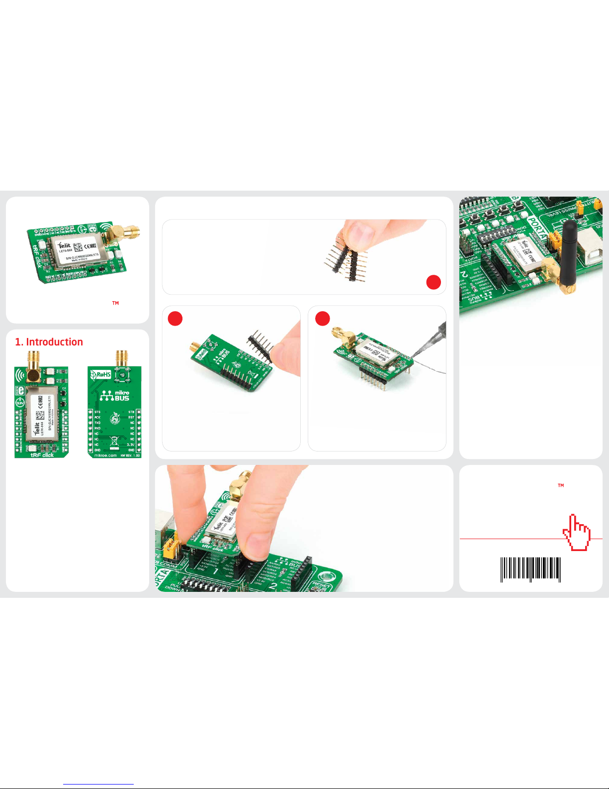
1. Introduction
Once you have soldered the headers your
board is ready to be placed into the desired
mikroBUS™ socket. Make sure to align the
cut in the lower-right part of the board
with the markings on the silkscreen at the
mikroBUS™ socket. If all the pins are aligned
correctly, push the board all the way
into the socket.
3. Plugging the board in
2 3
2. Soldering the headers
1
4. Essential features
Turn the board upward again. Make sure
to align the headers so that they are
perpendicular to the board, then solder the
pins carefully.
Turn the board upside down so that
the bottom side is facing you upwards.
Place shorter pins of the header into the
appropriate soldering pads.
Before using your click™ board, make
sure to solder 1x8 male headers to both
left and right side of the board. Two
1x8 male headers are included with the
board in the package.
click
BOARD
www.mikroe.com
tRF click Manual
ver. 1.00
0 100000 025895
tRF Click™ is an add-on board in mikroBUS™
form factor. It’s a compact and easy solution
for adding 868MHz RF communication
to your design. It features the Telit
LE70-868 - 868MHz transceiver module,
an SMA connector for an antenna as well
as two radio communication LEDs. tRF
Click™ communicates with the target board
microcontroller via mikroBUS™ UART (Rx,
Tx), AN, RST, PWM and INT lines. The board
is designed to use 3.3V power supply only.
A LED diode serves as a power indicator.
clicktRF
tRF Click™ with LE70-868 IC represents a
868MHz RF transceiver module with an
embedded stack that is easy to integrate
and use in point-to-point or star network
topologies. The board enables radio data
rates from 4.8 to 57.6 kbps with maximum
output power of 500mW and a range of
over 4000 meters (maximum tested range)
in open space. The board contains radio
transmit (red) and receive (yellow) LEDs.
Page 2
8. Support
MikroElektronika oers Free Tech Support
(www.mikroe.com/support/) until the
end of product lifetime, so if something goes
wrong, we are ready and willing to help!
7. Code Examples
.com
Once you have done all the necessary
preparations, it’s time to get your click™ board
up and running. We have provided examples
for mikroC™, mikroBasic™ and mikroPascal™
compilers on our Libstock website. Just
download them and you are ready to start.
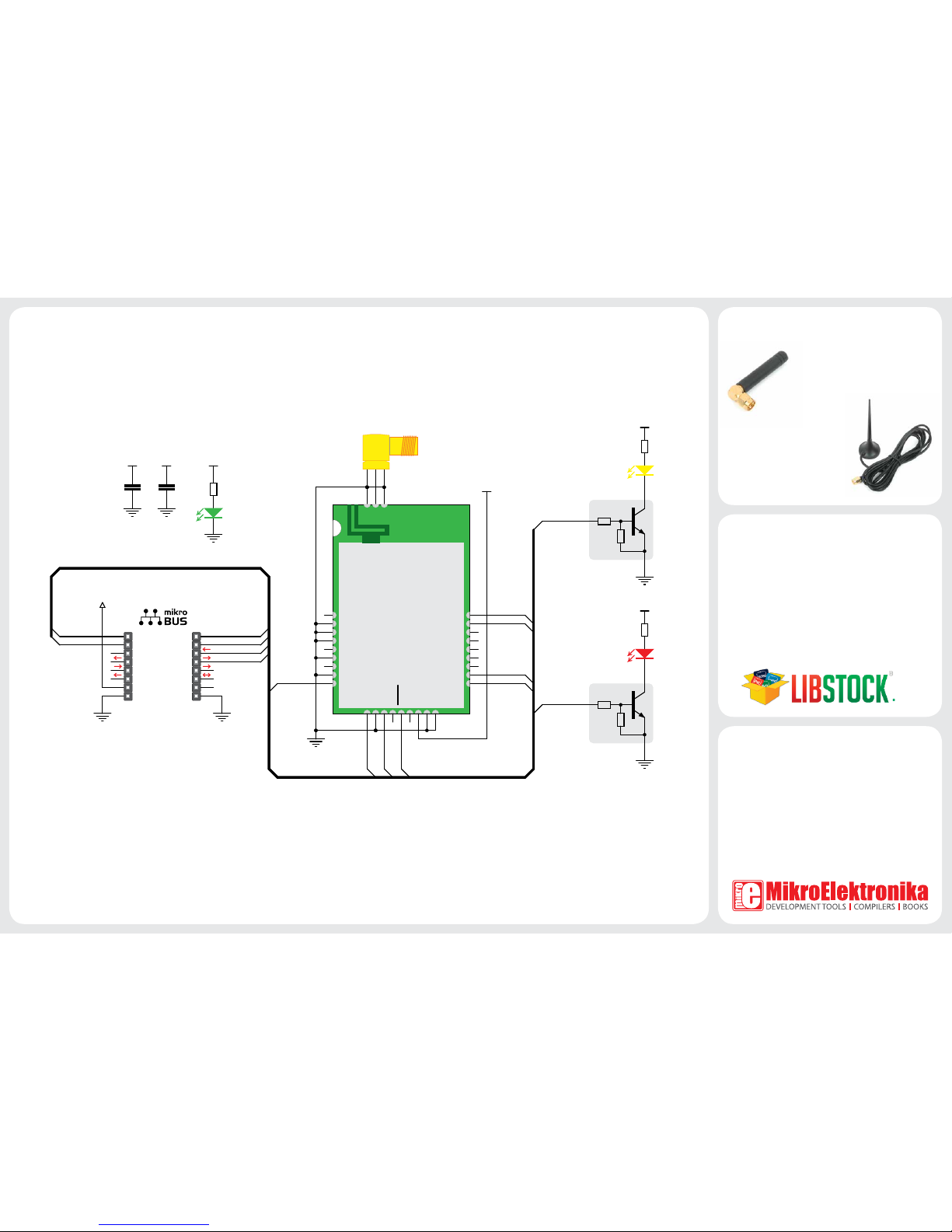
5. tRF Click™ Board Schematic
C1
2.2uF
AN
RST
CS
SCK
MOSI
MISO
+3.3V
GND
PWM
INT
RX
TX
SCL
SDA
+5V
GND
MIKROBUS DEVICE CONN.
R1
2K2
LD1
RST
VCC-3.3
VCC-3.3VCC-3.3
10
11
12
13
14
15
16
17
18 1
2
3
4
5
6
7
8
9
IO2
IO8_AD_DA
IO3
PDI_CLK
GND
GND
GND
PDI_DATA
GND
PROG
GND
WKP/STB IO1
IO4
IO5
IO6
IO7
IO9
28293019
20
21
22
23
24
25
26
27
TXD
GND
RXD
RTS
RESET
CTS
VDD
GND
GND
GND
ANT
GND
Telit RF
U1
RXD
TXD
TXD
RXD
RST
VCC-3.3
STB IO1
IO2
ACK
STAT
STB STAT
ACK
C2
100nF
VCC-3.3
CN1
ANT_SMA
LD2
LD3
R4
2K2
R3
2K2
VCC-3.3
VCC-3.3
IO2
IO1
R1
R2
Q1
PDTC114EU
R1
R2
Q2
PDTC114EU
MikroElektronika assumes no responsibility or liability for any errors or inaccuracies that may appear in the present document.
Specication and information contained in the present schematic are subject to change at any time without notice. Copyright © 2014 MikroElektronika. All rights reserved.
tRF click™ board also contains
an SMA right angle conncetor
for an external 868Mhz an-
tenna. The an-
tenna is not provided with the package,
but can be ordered from
MikroElektronika’s online
store.
6. Antenna
 Loading...