

Page 1

ARM
MINI
The whole MSP432 development board tted
in DIP40 form factor, containing powerful
MSP432P401R microcontroller.
MINI-M4
development board for MSP432
Page 2

I want to express my thanks to you for being interested in our products and for having
condence in MikroElektronika.
The primary aim of our company is to design and produce high quality electronic products
and to constantly improve the performance thereof in order to better suit your needs.
The MSP432, ARM® and Windows® logos and product names are trademarks of Texas Instruments®, ARM® Holdings and Microsoft® in the U.S.A. and other countries.
TO OUR VALUED CUSTOMERS
Nebojsa Matic
General Manager
Page 3

Page 3
Introduction to MINI-M4 for MSP432 4
Key features 4
System specications 5
1. Programming with mikroBootloader 6
step 1 – Connecting MINI-M4 for MSP432 6
step 2 – Browsing for .HEX le 7
step 3 – Selecting .HEX le 7
step 4 – Uploading .HEX le 8
step 5 – Finish upload 9
2. Schematic 10
3. Pinout 11
4. Dimensions 12
Table of Contents
Page 4

Page 4
Introduction to MINI-M4 for MSP432
Key features
01
02
03
04
05
06
07
Connection pads
micro USB connector
DATA LED
STAT LED
POWER supply LED
Reset button
Power supply regulator
MSP432P401RIRGC microcontroller
32.768kHz Crystal oscillator
48 MHz Crystal oscillator
08
09
10
Miniature and powerful development tool designed to
work as stand alone device or as MCU card in DIP40 socket.
MINI-M4 for MSP432 is pre programmed with USB UART Bootloader
so it is not necessary to have external programmer.
If there is need for external programmers (mikroProg™ or ST-LINK V2)
attach it to MINI-M4 for STM32 via pads marked with TCK/SWC, TMS/
SWD, INT0, INT1.
Page 5

Page 5
System specications
power supply
3.3V via pads or 5V via USB
board dimensions
50.8 x 17.78mm (2 x 0.7“)
weight
~6g (0.013 lbs)
power consumption
depends on MCU state (max current
into 3.3V pad is 300mA)
01
02
03 04 05
06
07
08
10
09
Page 6

Page 6
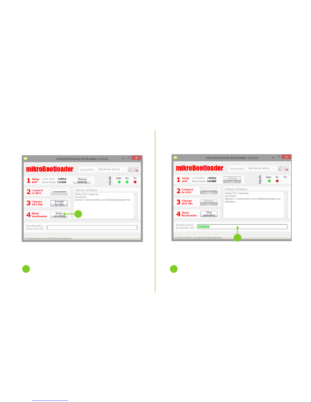
1. Programming with mikroBootloader
You can program the microcontroller with the bootloader which
is pre-programmed into the device by default. To transfer
.hex le from a PC to MCU you need bootloader software
(mikroBootloader USB UART) which can be downloaded from:
After the software is downloaded unzip it to the desired location and start mikroBootloader USB UART software.
Figure 1-1: USB UART mikroBootloader
step 1 – Connecting MINI-M4
01
01
To start, connect the USB cable, or if already connected
press the Reset button on your MINI-M4 board. Click the
Connect button within 5s to enter the bootloader mode,
otherwise existing microcontroller program will execute.
https://download.mikroe.com/examples/starter-boards/mini/msp432/minim4-msp432-bootloader-v242.zip
mikroBootloader USB UART MINI-M4 for MSP432.zip
WinRAR ZIP archive
mikroBootloader USB UART MINI-M4 for MSP432
File folder
Firmware
File folder
Mini-M4 for MSP432
Bootloader v1.00.hex
HEX File
Software - Windows
File folder
mikroBootloader USB UART
v2.4.2.exe
Bootloader tool for mikroElektron...
Page 7

Page 7
step 3 – Selecting .HEX le step 2 – Browsing for .HEX le
Figure 1-2: Browse for HEX Figure 1-3: Selecting HEX
01 01
02
01
01
Click the ”Browse for HEX” button and from a
pop-up window (Figure 1-3) choose the .HEX le
which will be uploaded to MCU memory.
Select .HEX le using open dialog window.
Click Open.
02
Page 8
Page 8
step 4 – Uploading .HEX le
Figure 1-4: Begin uploading Figure 1-5: Progress bar
01
01
01 01
To start .HEX le bootloading click the
Begin uploading button.
You can monitor .HEX le uploading via progress bar
Page 9

Page 9
step 5 – Finish upload
Figure 1-6: Restarting MCU
Figure 1-7: mikroBootloader ready for next job
01
01
Click OK after uploading is nished and wait for 5
seconds. Board will automatically reset and your
new program will execute.
Page 10
Page 10
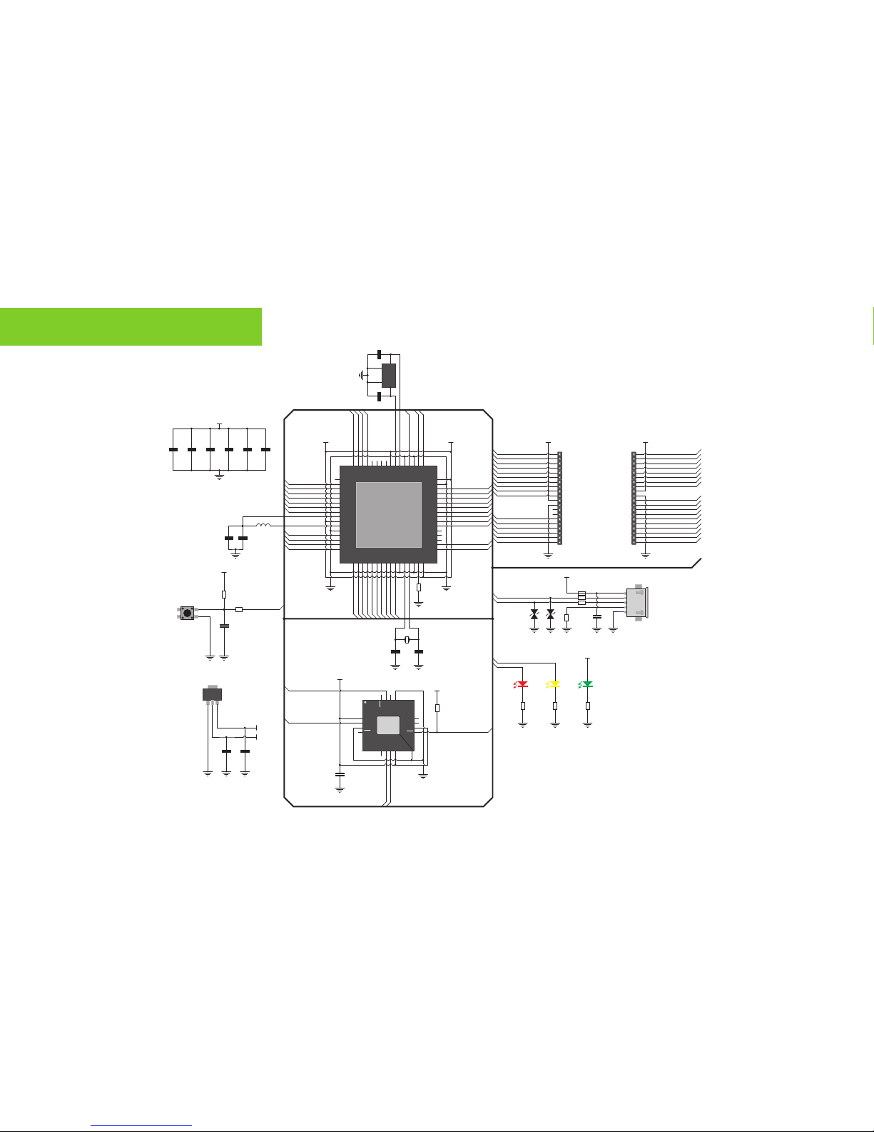
2. Schematic
HD1 HD2
SPI1-SS
I2C-SCL
CAN-Rx
INT0
PWM0
CAN-Tx
I2C-SDA
INT1
INT2
INT3
SPI1-MISO
SPI1-MOSI
SPI1-SCK
PWM1
PWM2
PWM3
UART0-Tx
UART0-Rx
AN0
AN1
AN2
AN3
AN4
AN5
AN6
UART1-Tx
UART1-Rx
SPI0-SS
SPI0-MISO
SPI0-MOSI
SPI0-SCK
TCK/SWC
TMS/SWD
TDI
TDOTDO
1
2
3
4
5
6
7
8
9
10
11
12
13
14
15
16
17
18
19
20 21
22
23
24
25
26
27
28
29
30
31
32
33
34
35
36
37
38
39
40nMCLR
VDD
VSS
VDD
VSS
3V3 3V3
3
1
2
VOUT
GND
VIN
U2
NCP1117ST33
C2
10µF
VCC-USB
3V3
T1
R4
100k
R5
220
3V3
RESET
LD3LD1 LD2
R12
470
R13
470
R14
470
3V3
D_N
D_P
R8
1M
1
2
3
4
5
ID
D+
D-
VBUS
GND
CN1
uUSB
FP1
DZ1 DZ2
R6 27
R7 27USBD_P
USBD_N
3V3
P1.0
1
P1.1
2
P1.2
3
P1.3
4
P1.4
5
P1.5
6
P1.6
7
P1.7
8
VCORE
9
DVCC1
10
VSW
11
DVSS1
12
P2.0
13
P2.1
14
P2.2
15
P2.3
16
P8.0
17
P8.118P3.0
19
P3.1
20
P3.2
21
P3.322P3.4
23
P3.5
24
P3.6
25
P3.726AVSS3
27
PJ.0
28
PJ.1
29
AVSS130DCOR
31
AVCC1
32
P4.2
33
P4.3
34
P4.4
35
P4.5
36
P4.6
37
P4.7
38
P5.0
39
P5.1
40
P5.2
41
P5.3
42
P5.4
43
P5.5
44
P5.6
45
P5.7
46
DVSS2
47
DVCC2
48
P6.649P6.7
50
DVSS3
51
RSTn
52
AVSS2
53
PJ.254PJ.3
55
AVCC2
56
P7.057P7.158P7.259P7.3
60
PJ.461PJ.5
62
SWDIO
63
SWCLK
64
U1
MSP432P401RIRGC
SWCLK/TCK
SWDIO/TMS
TDO
TDI
P1.2/UART_RX
P1.3/UART_TX
P1.4/SPI_SS
P1.5/SPI_SCK
P1.6/SPI_MOSI
P1.7/SPI_MISO
GND
P2.0/INT0
P2.1/INT1
P2.2/UART_RX
P2.3/UART_TX
GND
P3.4/SPI_SS
P3.7/SPI_MISO
P3.6/SPI_MOSI
3V3
P6.6/I2C_SDA
P6.7/I2C_SCL
GND
P8.1/PWM
P8.0/PWM
P3.5/SPI_SCK
P4.7/AN
P5.0/AN
P5.1/AN
P5.2/AN
P5.3/AN
P5.4/AN
P5.5/AN
P5.5/AN
P4.7/AN
P5.0/AN
P5.1/AN
P5.2/AN
P5.3/AN
P5.4/AN
P3.1/INT2
P3.0/INT3
P5.7/PWM
P5.6/PWM
RESET
P3.2/UART_RX
P3.3/UART_TX
RESET
P1.1/FT_RST
P3.1/INT2
P3.0/INT3
P8.1/PWM
P8.0/PWM
P3.4/SPI_SS
P3.7/SPI_MISO
P3.6/SPI_MOSI
P3.5/SPI_SCK
P5.7/PWM
P5.6/PWM
P2.2/UART_RX
P2.3/UART_TX
P3.2/UART_RX
P3.3/UART_TX
P6.6/I2C_SDA
P6.7/I2C_SCL
TDO
TDI
P2.0/INT0
P2.1/INT1
SWCLK/TCK
SWDIO/TMS
P1.4/SPI_SS
P1.5/SPI_SCK
P1.6/SPI_MOSI
P1.7/SPI_MISO
P1.2/UART_RX
P1.3/UART_TX
P1.1/FT_RST
3V3
GND
3V3
3V3
USBD_P
USBD_N
P4.3
P4.2
P4.3
P4.2
VCCIO
RXD
GND
CTS
CB2
RST
VCC
CB1
CB0
GND
RTS
TXD
CB3
DPDM3V3
GND PAD
U3
FT230x
R1
10k
L1
10µH
C3
4.7µF
GND GND
Y2
32.768kHz
OSC1
1
GND
2
OSC2
3
GND
4
Y1
48MHz
C5
12pF
C7
12pF
VCC-USB
C6
10µF
C16
10µF
C17
10µF
R2
91k
C12
0.10µF
C1
0.10µFC40.10µFC90.10µF
C11
0.10µF
C14
0.10µF
C13
0.10µF
C15
0.10µF
C8
22pF
C10
22pF
Page 11

Page 11
3. Pinout
P5.6
P5.7
SPI1-SCK P3.5
PWM1 P8.0
PWM0 P8.1
INT3 P3.0
CRX NC
CTX NC
GND GND
3.3V Power supply 3.3V
INT2
P3.1
P4.7
P5.0
SPI1-SS P3.4
AN4 P5.1
AN3 P5.2
AN2 P5.3
AN1 P5.4
AN0 P5.5
RST
Pin functionsPin functions
CAN
Analog I/O
P3.3
P3.2
P3.7
P3.6
P2.3
P2.2
P6.6
P6.7
TDO
TDI
GND
3.3V
P2.1
P2.0
TMS
TLK
P1.4
P1.5
P1.6
SPI1-MISO
SPI1-MOSI
U0TX
U0RX
GND
3.3V Power supply
INT1
INT0
TMS/SWD
SPI0-MOSI
SPI0-MISO
I2C
UART0
TCK/SWC
SPI0-SS
SPI0-SCK
SPI0
AN5
AN6
SPI LinesInterrupt Lines
Analog Lines
I2C Lines
UART lines CAN lines PWM lines
PWM2
PWM3
TDI
TDO
I2C-SCL
I2C-SDA
U1TX
U1RX
UART1
P1.7
Page 12
Page 12
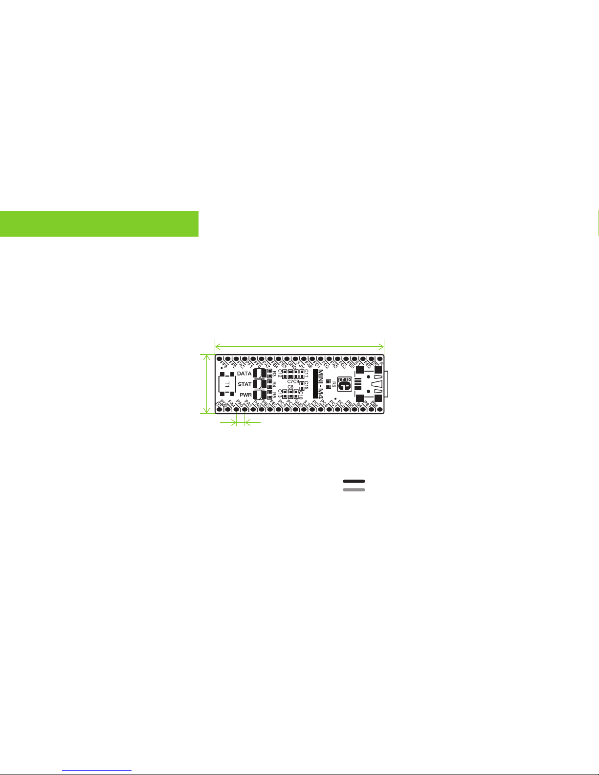
4. Dimensions
50.8
2000
2.54
100
17.78
700
MSP432
50.8
2000
2.54
100
Legend
mm
mils
MSP432
Page 13
Page 13
Notes:
Page 14

Page 14
Notes:
Page 15

Page 15
DISCLAIMER
All the products owned by MikroElektronika are protected by copyright law and international copyright treaty. Therefore, this manual is to be treated as any
other copyright material. No part of this manual, including product and software described herein, may be reproduced, stored in a retrieval system, translated
or transmitted in any form or by any means, without the prior written permission of MikroElektronika. The manual PDF edition can be printed for private or
local use, but not for distribution. Any modication of this manual is prohibited.
MikroElektronika provides this manual ‘as is’ without warranty of any kind, either expressed or implied, including, but not limited to, the implied warranties
or conditions of merchantability or tness for a particular purpose.
MikroElektronika shall assume no responsibility or liability for any errors, omissions and inaccuracies that may appear in this manual. In no event shall
MikroElektronika, its directors, ocers, employees or distributors be liable for any indirect, specic, incidental or consequential damages (including damages
for loss of business prots and business information, business interruption or any other pecuniary loss) arising out of the use of this manual or product,
even if MikroElektronika has been advised of the possibility of such damages. MikroElektronika reserves the right to change information contained in this
manual at any time without prior notice, if necessary.
TRADEMARKS
The MikroElektronika name and logo, the MikroElektronika logo, mikroC™, mikroBasic™, mikroPascal™, MINI™, EasyMX PRO™, mikroBUS™, click™ boards,
mikroProg™, and mikromedia™ are trademarks of MikroElektronika. All other trademarks mentioned herein are property of their respective companies.
All other product and corporate names appearing in this manual may or may not be registered trademarks or copyrights of their respective companies, and
are only used for identication or explanation and to the owners’ benet, with no intent to infringe.
Copyright © 2017 MikroElektronika. All Rights Reserved.
HIGH RISK ACTIVITIES
The products of MikroElektronika are not fault – tolerant nor designed, manufactured or intended for use or resale as on – line control equipment in
hazardous environments requiring fail – safe performance, such as in the operation of nuclear facilities, aircraft navigation or communication systems,
air trac control, direct life support machines or weapons systems in which the failure of Software could lead directly to death, personal injury or
severe physical or environmental damage (‘High Risk Activities’). MikroElektronika and its suppliers specically disclaim any expressed or implied warranty of tness for High Risk Activities.
Page 16

If you want to learn more about our products, please visit our website at www.mikroe.com
If you are experiencing some problems with any of our products or just need additional
information, please place your ticket at helpdesk.mikroe.com
If you have any questions, comments or business proposals,
do not hesitate to contact us at oce@mikroe.com
ARM
MINI
 Loading...