

Page 1
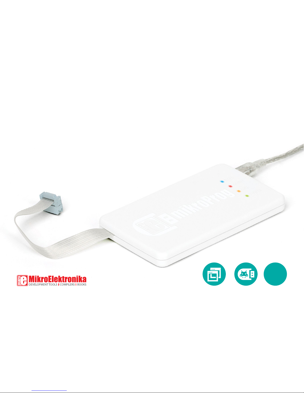
mikroProg
™
mikroProg™ for 8051 is a fast USB programmer. With it’s
outstanding performance, simplicity and unique design it is a
great tool for programming 8051 microcontrollers from Atmel®
for 8051
8051
Page 2

Page 3
I want to express my thanks to you for being interested in our products and
for having condence in MikroElektronika.
The primary aim of our company is to design and produce high quality
electronic products and to constantly improve the performance thereof in
order to better suit your needs.
TO OUR VALUED CUSTOMERS
Nebojsa Matic
General Manager
Page 4

Page 5

Introduction to mikroProg™ 6
Key features 7
1. Driver installation 8
step 1 – Start installation 9
step 2 – Accept EULA 9
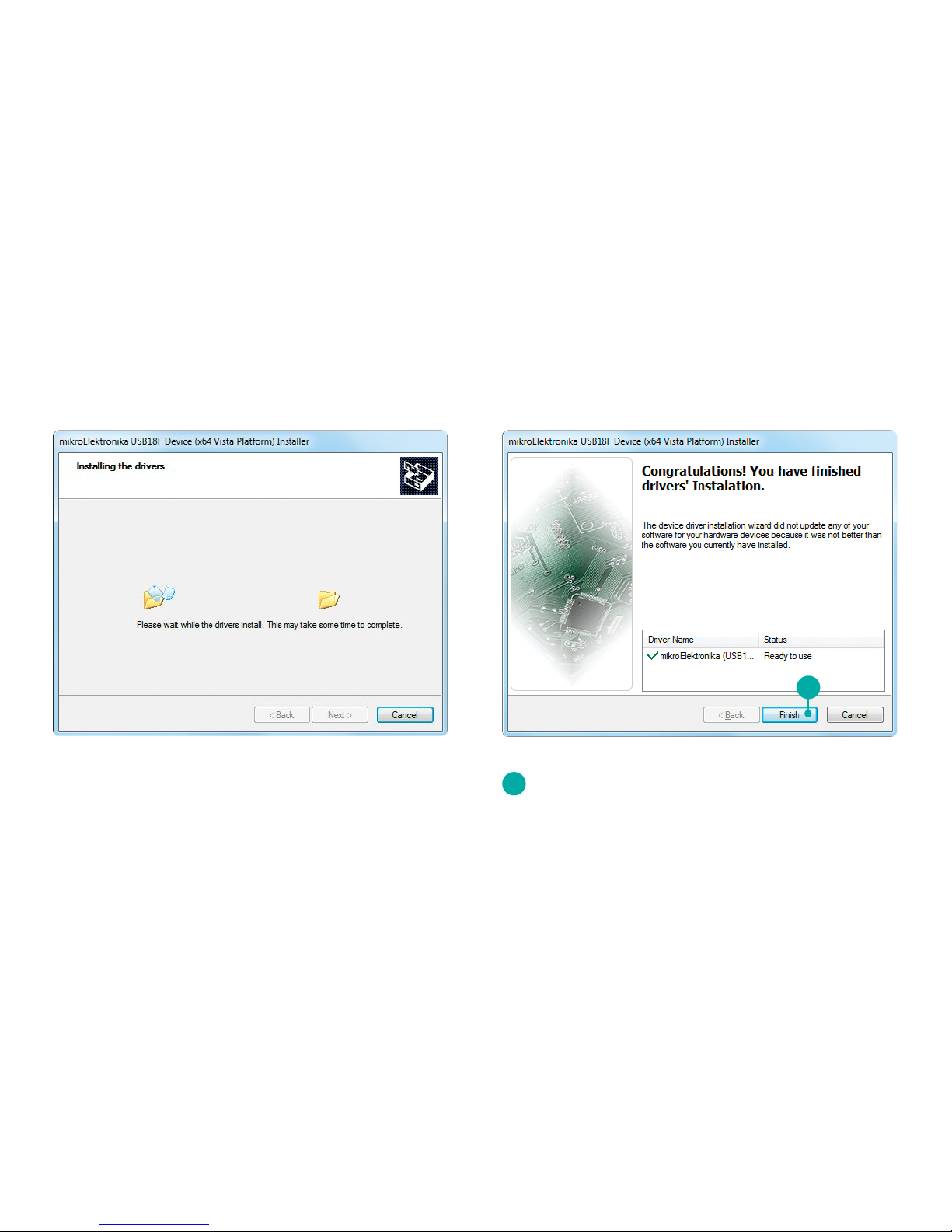
step 3 – Installing the drivers 10
step 4 – Finish installation 10
2. Connecting to a PC 11
3. 8051Flash software 12
4. Connecting with a target device 14
5. Connector Pinout 15
6. Connection schematic example 16
40-pin AT89S8253 schematic 17
Table of Contents
Page 6

mikroProg™ for 8051 is a
fast USB programmer. It is a
great tool for programming
8051 microcontrollers from
Atmel®. Outstanding performance, easy operation,
elegant design and low
price are it’s top features.
Introduction to mikroProg
™
Page 6
Page 7

Page 7
01
02
03
04
05
06
Flat cable
USB MINIB connector
DATA transfer indication LED
ACTIVE indication LED
LINK indication LED
POWER indication LED
06
05
04
03
01
02
Key features
What you see
Page 8

Page 8
1. Driver installation
On-board mikroProg™ requires drivers in order to work.
Drivers can be found on the link bellow:
www.mikroe.com/downloads/get/131/mikroprog_
drivers_v200.zip
When you download the drivers, please extract les from
the ZIP archive. Folder with extracted les contains folders
with drivers for dierent operating systems. Depending on
which operating system you use, choose adequate folder
and open it.
In the opened folder you should be
able to locate the driver setup le.
Double click on setup le to begin
installation of the programmer drivers.
mikroprog_drivers_v200.zip
WinRAR ZIP archive
Win 98
Windows (32 bit)
- Vista, Win 2008,
7, 8, 8.1
Win 2000, XP,
2003 32-bit
Windows (64 bit)
- Vista, Win 2008,
7, 8, 8.1
USB18PRG-Vista-x64.EXE
Win XP, 2003
64-bit
Page 9

Page 9
step 2 – Accept EULAstep 1 – Start installation
1
In welcome screen click the Next> button
2
3
Select I accept this EULA option
Click the Next> button
1 3
2
Page 10
Page 10
step 3 – Installing the drivers step 4 – Finish installation
4
Click the Finish button to end installation process
4
Page 11

After driver installation is complete, you can connect the programmer with your PC
using USB cable provided with the package. Green POWER LED should turn ON,
indicating the presence of power supply. Amber-colored LINK LED will turn ON when
link between mikroProg™ for 8051 and PC is established. Link can be established only
when correct drivers are installed on your PC.
2. Connecting to a PC
Page 11
Page 12
Page 12
mikroProg™ for 8051 programmer requires special
programming software called 8051Flash. This software is
used for programming ALL of 8051 microcontrollers from
Atmel®. It features intuitive interface and SingleClick™
programming technology. Software installation is available
on the following link:
www.mikroe.com/downloads/get/130/8051ash_
programmer_v210.zip
After downloading, extract the package and double click the
executable setup le, to start installation.
3. 8051Flash software
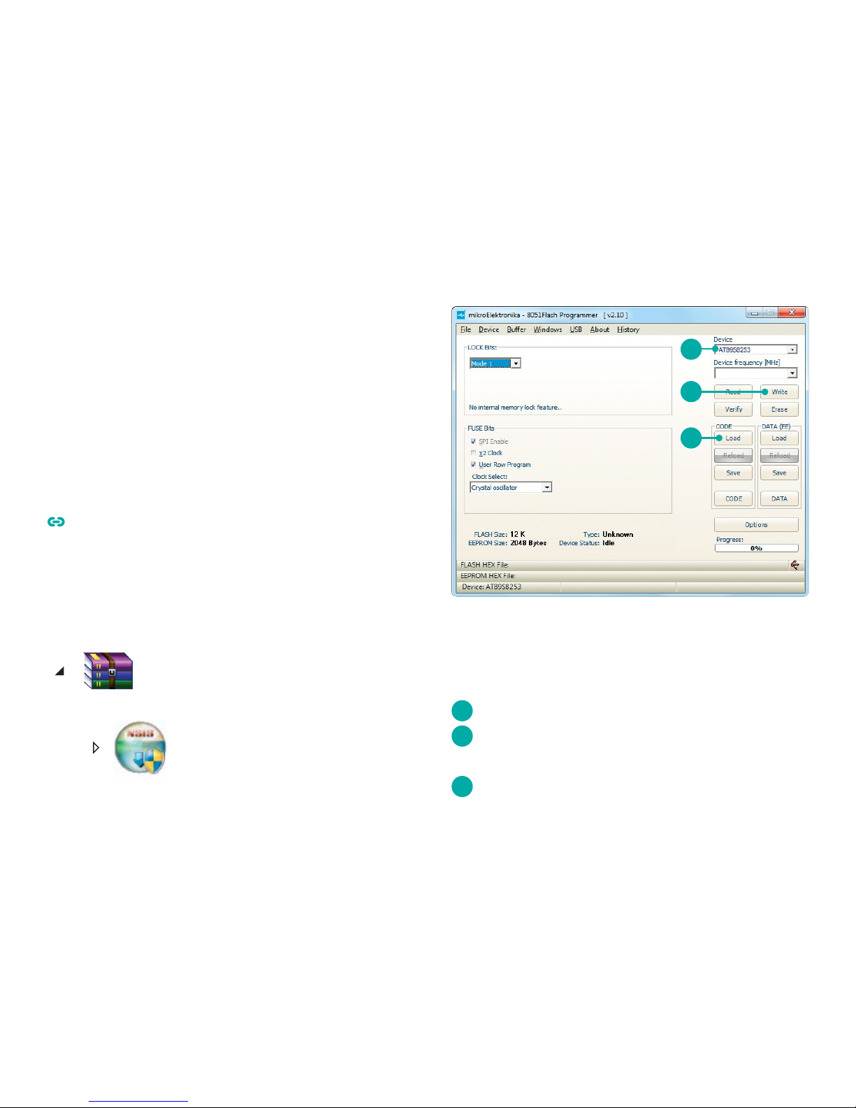
Figure 3-1: 8051Flash software window
Quick Guide
1
2
3
Select the microcontroller to be programmed
Click the Load button to open pop-up window and select
the .hex code to be loaded in microcontroller
Click the Write option to start programming
1
3
2
8051Flash_v210_setup.exe
8051ash_programmer_v210.zip
WinRAR ZIP archive
Page 13
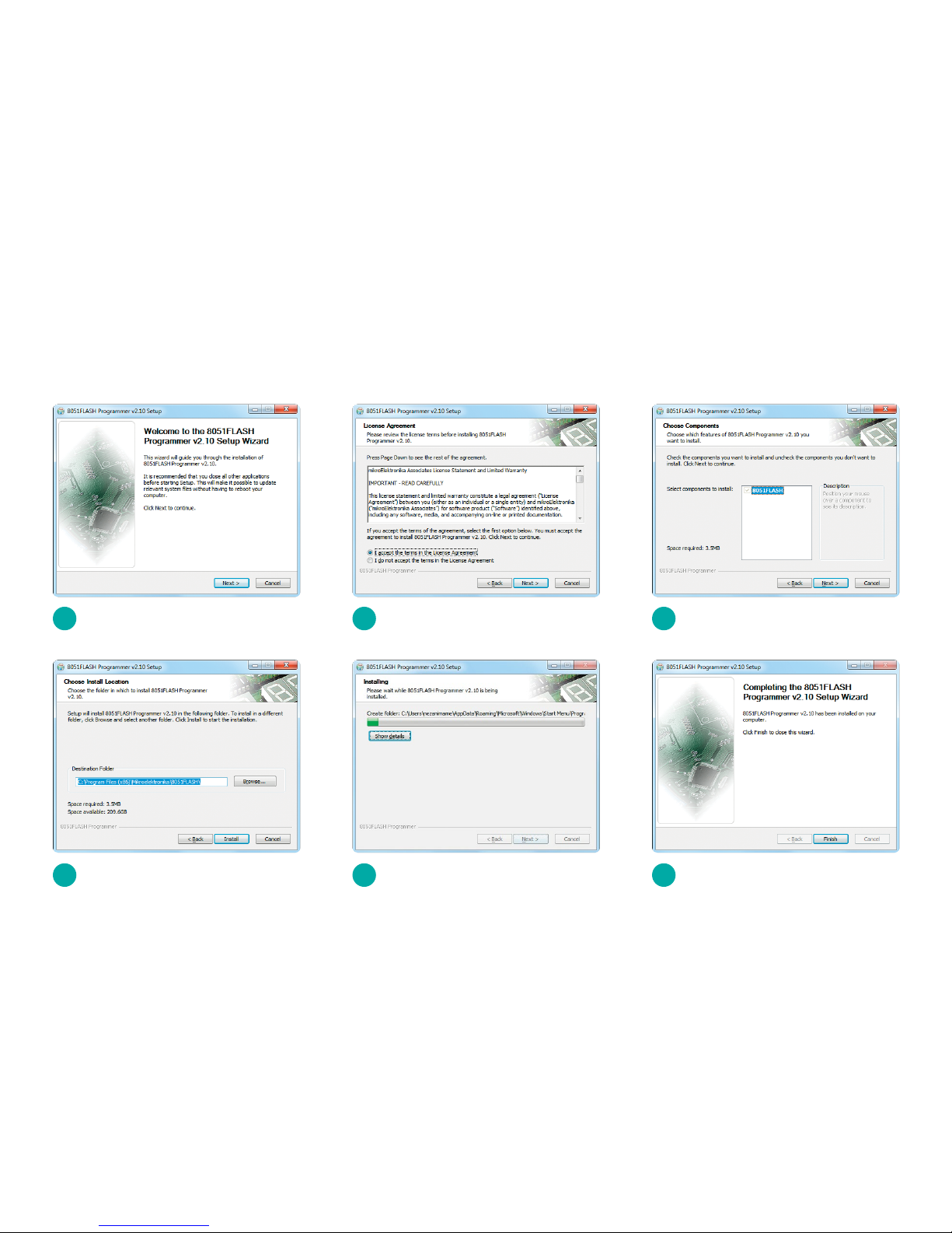
Page 13
1
4
2
5
3
6
Start Installation
Choose destination folder
Accept EULA and continue
Installation in progress
Click Next > button
Finish installation
Software installation wizard
Page 14

Page 14
4. Connecting with a target device
For connection with a target device mikroProg™ uses IDC10
connector, as shown on Figure 4-1. In order to make proper
connection with the target board it is necessary to pay attention
to IDC10 connector pinout. Every pin has a dierent purpose and
for easy orientation IDC10 connector is marked with a little knob
and incision between pins number 9 and 7, Figure 5-1.
Figure 4-1:
IDC10 JTAG
connector
Page 15

Page 15
Figure 5-1: Female connector pinout
1
3
5
7
9 10
8
6
4
2
1
3
5
7
9
MOSI - Master output slave input
NC - Not connected
RST - Reset pin
SCK - Clock
MISO - Master input slave output
5. Connector Pinout
2
4
6
8
10
VCC - Power supply
SS - Slave port select
NC - Not connected
NC - Not connected
GND - Ground
Page 16
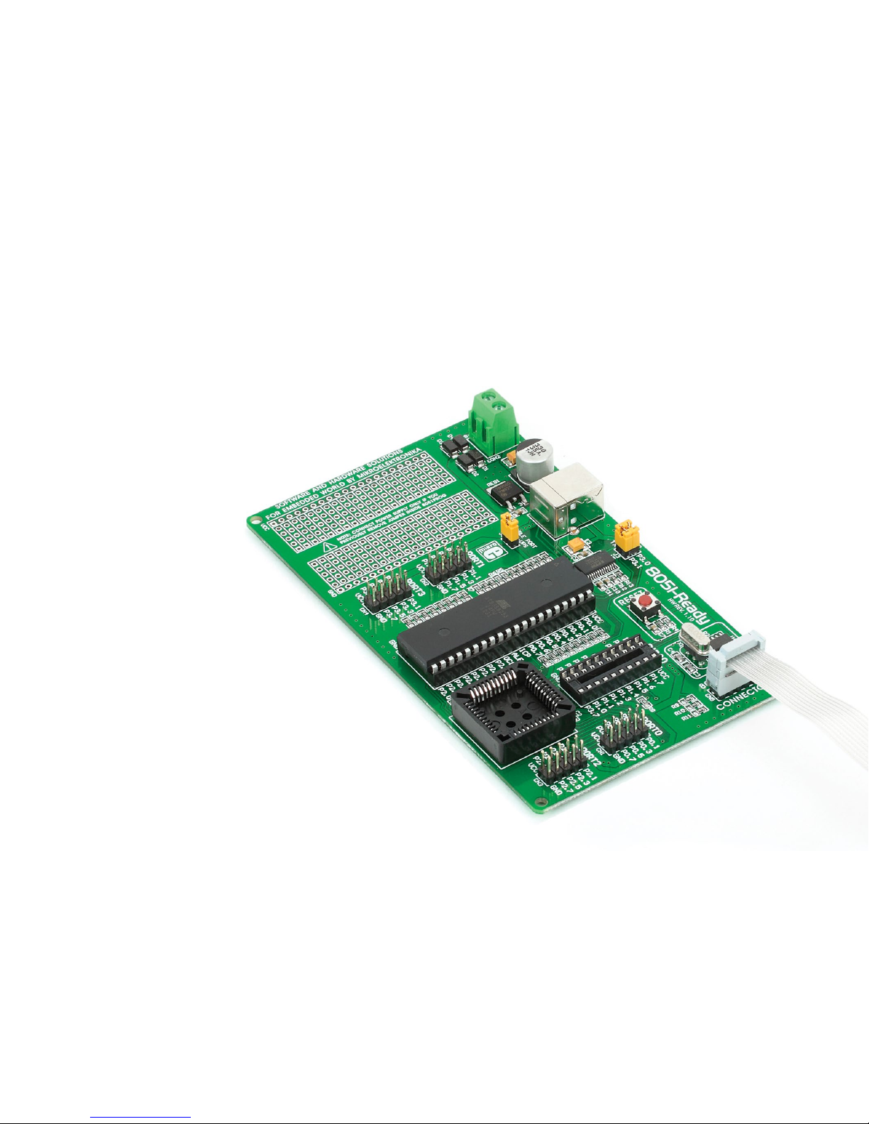
Following example demonstrate connections with
one of the most popular
supported microcontroller
(Figure 6-1). MCU use
MISO, MOSI, SCK, RST and
SS lines for programming.
In order for microcontroller
to work properly, decoupling capacitors must be
connected as close as possible to microcontroller’s
VCC pins. Whichever microcontroller you decide to
use, make sure to connect
each pin properly.
6. Connection schematic example
Page 16
Page 17

Page 17
Figure 6-1: Connection schematic for 40-pin AT89S8253 MCU via 2x5 male header
1
2
3
4
5
6
7
8 33
34
35
36
37
38
39
40
P1.0
P1.1
P1.2
P1.3
P1.4 (SS)
P1.5 (MOSI)
P1.6 (MISO)
P1.7 (SCK)
P0.4
P0.5
VCC
P0.0
P0.1
P0.2
P0.3
P0.6
9
10
11
12
13
14
15
16
RST
P3.0
P3.1
P3.2
P3.3
P3.4
P3.5
P3.6
17
18
19
20
XTAL2
XTAL1
GND
25
26
27
28
29
30
31
32
P2.6
P2.5
P0.7
ALE/PROG
PSEN
P2.7
21
22
23
24
P2.1
P2.0
P2.2
AT89S8253
P3.7
EA/VPP
P2.4
P2.3
U1
40 pin
VCC
X1
8MHz
C1
22pF
C2
22pF
MOSI
RST
SCK
MISO
SS
VCC
C3
100nF
VCC
Page 18

Page 19

Page 19
DISCLAIMER
All the products owned by MikroElektronika are protected by copyright law and international copyright treaty. Therefore, this manual is to be treated
as any other copyright material. No part of this manual, including product and software described herein, may be reproduced, stored in a retrieval
system, translated or transmitted in any form or by any means, without the prior written permission of MikroElektronika. The manual PDF edition can
be printed for private or local use, but not for distribution. Any modication of this manual is prohibited.
MikroElektronika provides this manual ‘as is’ without warranty of any kind, either expressed or implied, including, but not limited to, the implied
warranties or conditions of merchantability or tness for a particular purpose.
MikroElektronika shall assume no responsibility or liability for any errors, omissions and inaccuracies that may appear in this manual. In no event shall
MikroElektronika, its directors, ocers, employees or distributors be liable for any indirect, specic, incidental or consequential damages (including
damages for loss of business prots and business information, business interruption or any other pecuniary loss) arising out of the use of this manual
or product, even if MikroElektronika has been advised of the possibility of such damages. MikroElektronika reserves the right to change information
contained in this manual at any time without prior notice, if necessary.
HIGH RISK ACTIVITIES
The products of MikroElektronika are not fault – tolerant nor designed, manufactured or intended for use or resale as on – line control
equipment in hazardous environments requiring fail – safe performance, such as in the operation of nuclear facilities, aircraft navigation
or communication systems, air trac control, direct life support machines or weapons systems in which the failure of Software could lead
directly to death, personal injury or severe physical or environmental damage (‘High Risk Activities’). MikroElektronika and its suppliers
specically disclaim any expressed or implied warranty of tness for High Risk Activities.
TRADEMARKS
The MikroElektronika name and logo, mikroC
™
, mikroBasic™, mikroPascal™, Visual TFT™, Visual GLCD™, mikroProg™, Ready™, MINI™, mikroBUS™, EasyPIC™,
EasyAVR
™
, Easy8051™, click™ boards and mikromedia™ are trademarks of MikroElektronika. All other trademarks mentioned herein are property of their
respective companies. All other product and corporate names appearing in this manual may or may not be registered trademarks or copyrights of their
respective companies, and are only used for identication or explanation and to the owners’ benet, with no intent to infringe.
Windows® logos and product names are trademarks of Microsoft® in the U.S.A. and other countries.
Copyright © 2014 MikroElektronika. All Rights Reserved.
Page 20
mikroProg for 8051 manual
ver 1.00a
∫ If you want to learn more about our products, please visit
our website at www.mikroe.com
∫ If you are experiencing some problems with any of our
products or just need additional information, please place
your ticket at www.mikroe.com/support
∫ If you have any questions, comments or business proposals,
do not hesitate to contact us at oce@mikroe.com
Designed by
MikroElektronika Ltd.
8051
 Loading...