

Page 1

™
Keypad 4x4
All Mikroelektronika’s development systems feature a large number of peripheral
modules expanding microcontroller’s range of application and making the
process of program testing easier. In addition to these modules, it is also
possible to use numerous additional modules linked to the development system
through the I/O port connectors. Some of these additional modules can operate
as stand-alone devices without being connected to the microcontroller.
Manual
Additional board
MikroElektronika
Page 2
Keypad 4x4
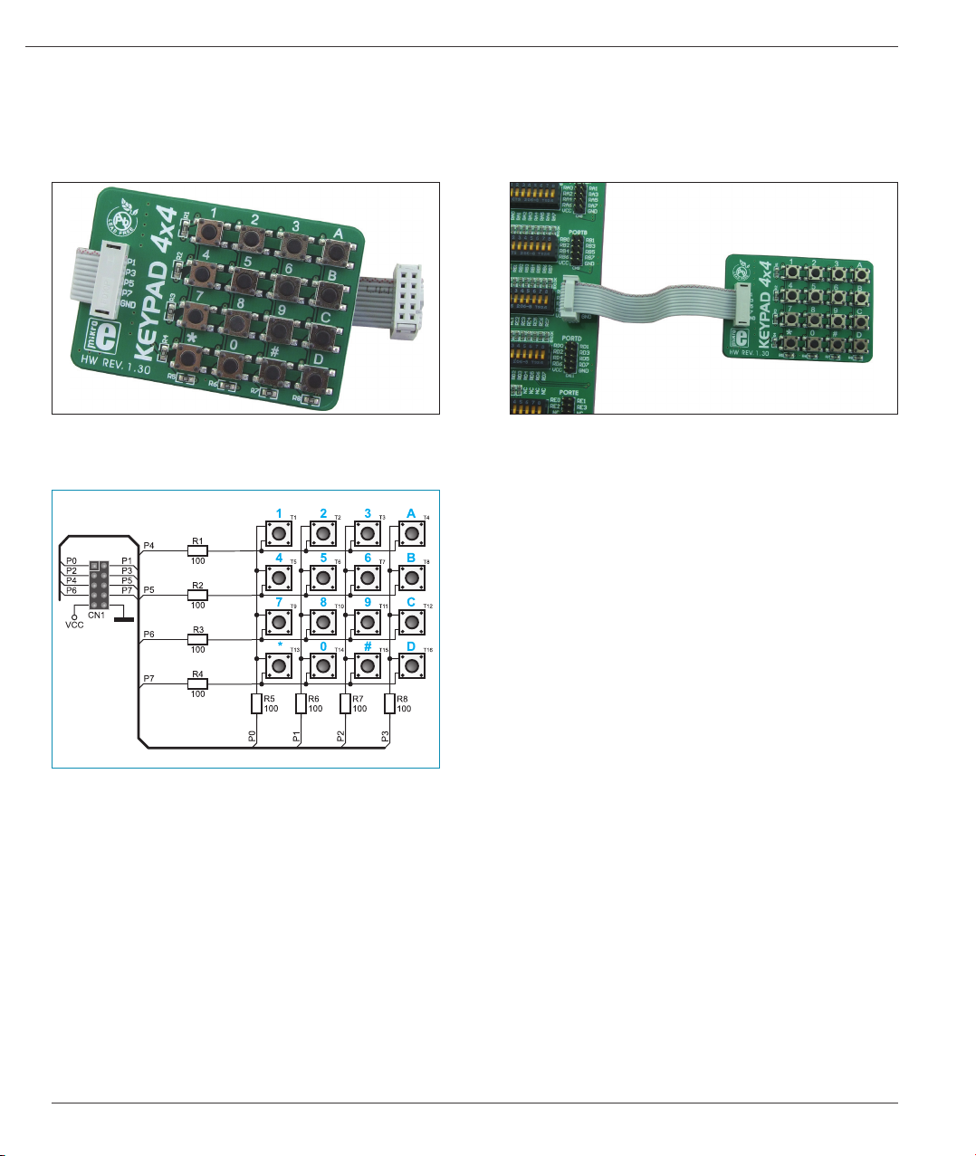
Keypad 4x4
Keypad 4x4 is used for loading numerics into the microcontroller. It consists of 16 buttons arranged in a form of an array containig four
lines and four columns. It is connected to the development system by regular IDC 10 female connector plugged in some development
system’s port.
Figure 1: Keypad 4x4
Figure 3: Keypad 4x4 connection schematic
A far easier way to load data by using keypad 4x4 is by employing ready-to-use funtions provided in the Keypad Library of any
Mikroelektronika’s compiler. On the following pages there are three simple examples written for PIC16F887 microcontrolller in mikroC,
mikroBasic and mikroPascal programming languages. In all cases, the number loaded via keypad is converted into the equivalent
ASCII code (0...9, A...F) and then it is displayed in the second line of LCD display. In this case, pull-down resistors are placed on output
pins RD0 - RD3 and are used to determine logic zero (0) in idle state.
Figure 2: Keypad 4x4 connected to development system
The keyboard is usually used as follows:
1.
Four microcontroller’s pins should be dened as outputs,
and other four pins should be dened as inputs. In order the
keypad to work properly, pull-down resistors should be placed
on the microcontroller’s input pins, thus dening logic state
when no button is pressed.
2.
Then, the output pins are set to logic one (1) and input pins’
logic state is read. By pressing any button, a logic one (1) will
appear on some input pin.
3.
By combining zeros and ones on the output pins, it is
determined which button is pressed.
MikroElektronika
Page 3

Keypad 4x4
Figure 4: Keypad, LCD and microcontroller connection schematic
Example 1: Program written in mikroC PRO for PIC
unsigned short kp, cnt, oldstate = 0;
char txt[6];
// Keypad module connections
char keypadPort at PORTD;
// End Keypad module connections
sbit LCD_RS at RB4_bit; // LCD module connections
sbit LCD_EN at RB5_bit;
sbit LCD_D4 at RB0_bit;
sbit LCD_D5 at RB1_bit;
sbit LCD_D6 at RB2_bit;
sbit LCD_D7 at RB3_bit;
sbit LCD_RS_Direction at TRISB4_bit;
sbit LCD_EN_Direction at TRISB5_bit;
sbit LCD_D4_Direction at TRISB0_bit;
sbit LCD_D5_Direction at TRISB1_bit;
sbit LCD_D6_Direction at TRISB2_bit;
sbit LCD_D7_Direction at TRISB3_bit;
// End LCD module connections
void main() {
cnt = 0; // Reset counter
Keypad_Init(); // Initialize Keypad
ANSEL = 0; // Congure AN pins as digital I/O
ANSELH = 0;
Lcd_Init(); // Initialize LCD
Lcd_Cmd(_LCD_CLEAR); // Clear display
Lcd_Cmd(_LCD_CURSOR_OFF); // Cursor off
Lcd_Out(1, 1, “1”);
Lcd_Out(1, 1, “Key :”); // Write message text on LCD
Lcd_Out(2, 1, “Times:”);
do {
kp = 0; // Reset key code variable
// Wait for key to be pressed and released
do
kp = Keypad_Key_Click(); // Store key code in kp variable
while (!kp);
// Prepare value for output, transform key to it’s ASCII value
switch (kp) {
//case 10: kp = 42; break; // ‘*’ // Uncomment this block for keypad4x3
//case 11: kp = 48; break; // ‘0’
//case 12: kp = 35; break; // ‘#’
//default: kp += 48;
case 1: kp = 49; break; // 1 // Uncomment this block for keypad4x4
case 2: kp = 50; break; // 2
case 3: kp = 51; break; // 3
case 4: kp = 65; break; // A
case 5: kp = 52; break; // 4
case 6: kp = 53; break; // 5
case 7: kp = 54; break; // 6
case 8: kp = 66; break; // B
case 9: kp = 55; break; // 7
case 10: kp = 56; break; // 8
case 11: kp = 57; break; // 9
case 12: kp = 67; break; // C
case 13: kp = 42; break; // *
case 14: kp = 48; break; // 0
case 15: kp = 35; break; // #
case 16: kp = 68; break; // D
}
if (kp != oldstate) { // Pressed key differs from previous
cnt = 1;
oldstate = kp;
}
else { // Pressed key is same as previous
cnt++;
}
Lcd_Chr(1, 10, kp); // Print key ASCII value on LCD
if (cnt == 255) { // If counter varialble overow
cnt = 0;
Lcd_Out(2, 10, “ “);
}
WordToStr(cnt, txt); // Transform counter value to string
Lcd_Out(2, 10, txt); // Display counter value on LCD
} while (1);
}
MikroElektronika
Page 4

Example 2: Program written in mikroBasic PRO for PIC
Keypad 4x4
program Keypad_Test
dim kp, cnt, oldstate as byte
txt as char[7]
‘ Keypad module connections
dim keypadPort as byte at PORTD
‘ End Keypad module connections
‘ Lcd module connections
dim LCD_RS as sbit at RB4_bit
LCD_EN as sbit at RB5_bit
LCD_D4 as sbit at RB0_bit
LCD_D5 as sbit at RB1_bit
LCD_D6 as sbit at RB2_bit
LCD_D7 as sbit at RB3_bit
LCD_RS_Direction as sbit at TRISB4_bit
LCD_EN_Direction as sbit at TRISB5_bit
LCD_D4_Direction as sbit at TRISB0_bit
LCD_D5_Direction as sbit at TRISB1_bit
LCD_D6_Direction as sbit at TRISB2_bit
LCD_D7_Direction as sbit at TRISB3_bit
‘ End Lcd module connections
main:
oldstate = 0
cnt = 0 ‘ Reset counter
Keypad_Init() ‘ Initialize Keypad
ANSEL = 0 ‘ Congure AN pins as digital I/O
ANSELH = 0
Lcd_Init() ‘ Initialize LCD
Lcd_Cmd(_LCD_CLEAR) ‘ Clear display
Lcd_Cmd(_LCD_CURSOR_OFF) ‘ Cursor off
Lcd_Out(1, 1, “Key :”) ‘ Write message text on LCD
Lcd_Out(2, 1, “Times:”)
while TRUE
kp = 0 ‘ Reset key code variable
‘ Wait for key to be pressed and released
while ( kp = 0 )
kp = Keypad_Key_Click() ‘ Store key code in kp variable
wend
‘ Prepare value for output, transform key to it”s ASCII value
select case kp
‘case 10: kp = 42 ‘ “*” ‘ Uncomment this block for keypad4x3
‘case 11: kp = 48 ‘ “0”
‘case 12: kp = 35 ‘ “#”
‘default: kp += 48
case 1
kp = 49 ‘ 1 ‘ Uncomment this block for keypad4x4
case 2
kp = 50 ‘ 2
case 3
kp = 51 ‘ 3
case 4
kp = 65 ‘ A
case 5
kp = 52 ‘ 4
case 6
kp = 53 ‘ 5
case 7
kp = 54 ‘ 6
case 8
kp = 66 ‘ B
case 9
kp = 55 ‘ 7
case 10
kp = 56 ‘ 8
case 11
kp = 57 ‘ 9
case 12
kp = 67 ‘ C
case 13
kp = 42 ‘ *
case 14
kp = 48 ‘ 0
case 15
kp = 35 ‘ #
case 16
kp = 68 ‘ D
end select
if (kp <> oldstate) then ‘ Pressed key differs from previous
cnt = 1
oldstate = kp
else ‘ Pressed key is same as previous
Inc(cnt)
end if
Lcd_Chr(1, 10, kp) ‘ Print key ASCII value on LCD
if (cnt = 255) then ‘ If counter varialble overow
cnt = 0
Lcd_Out(2, 10, “ “)
end if
WordToStr(cnt, txt) ‘ Transform counter value to string
Lcd_Out(2, 10, txt) ‘ Display counter value on LCD
wend
end.
MikroElektronika
Page 5

Keypad 4x4
Example 3: Program written in mikroPascal PRO for PIC
program Keypad_Test;
var kp, cnt, oldstate : byte;
txt : array[6] of byte;
// Keypad module connections
var keypadPort : byte at PORTD;
// End Keypad module connections
// Lcd module connections
var LCD_RS : sbit at RB4_bit;
LCD_EN : sbit at RB5_bit;
LCD_D4 : sbit at RB0_bit;
LCD_D5 : sbit at RB1_bit;
LCD_D6 : sbit at RB2_bit;
LCD_D7 : sbit at RB3_bit;
var LCD_RS_Direction : sbit at TRISB4_bit;
LCD_EN_Direction : sbit at TRISB5_bit;
LCD_D4_Direction : sbit at TRISB0_bit;
LCD_D5_Direction : sbit at TRISB1_bit;
LCD_D6_Direction : sbit at TRISB2_bit;
LCD_D7_Direction : sbit at TRISB3_bit;
// End Lcd module connections
begin
oldstate := 0;
cnt := 0; // Reset counter
Keypad_Init(); // Initialize Keypad
ANSEL := 0; // Congure AN pins as digital I/O
ANSELH := 0;
Lcd_Init(); // Initialize Lcd
Lcd_Cmd(_LCD_CLEAR); // Clear display
Lcd_Cmd(_LCD_CURSOR_OFF); // Cursor off
Lcd_Out(1, 1, ‘Key :’); // Write message text on Lcd
Lcd_Out(2, 1, ‘Times:’);
while TRUE do
begin
kp := 0; // Reset key code variable
// Wait for key to be pressed and released
while ( kp = 0 ) do
kp := Keypad_Key_Click(); // Store key code in kp variable
// Prepare value for output, transform key to it’s ASCII value
case kp of
//case 10: kp = 42; // ‘*’ // Uncomment this block for keypad4x3
//case 11: kp = 48; // ‘0’
//case 12: kp = 35; // ‘#’
//default: kp += 48;
1: kp := 49; // 1 // Uncomment this block for keypad4x4
2: kp := 50; // 2
3: kp := 51; // 3
4: kp := 65; // A
5: kp := 52; // 4
6: kp := 53; // 5
7: kp := 54; // 6
8: kp := 66; // B
9: kp := 55; // 7
10: kp := 56; // 8
11: kp := 57; // 9
12: kp := 67; // C
13: kp := 42; // *
14: kp := 48; // 0
15: kp := 35; // #
16: kp := 68; // D
end;
if (kp <> oldstate) then // Pressed key differs from previous
begin
cnt := 1;
oldstate := kp;
end
else // Pressed key is same as previous
Inc(cnt);
Lcd_Chr(1, 10, kp); // Print key ASCII value on Lcd
if (cnt = 255) then // If counter varialble overow
begin
cnt := 0;
Lcd_Out(2, 10, ‘ ‘);
end;
WordToStr(cnt, txt); // Transform counter value to string
Lcd_Out(2, 10, txt); // Display counter value on Lcd
end;
end.
MikroElektronika
Page 6

If you want to learn more about our products, please visit our website at www.mikroe.com
If you are experiencing some problems with any of our products or just need additional information, please place your ticket at
www.mikroe.com/en/support
If you have any questions, comments or business proposals, do not hesitate to contact us at offi ce@mikroe.com
 Loading...