

Page 1
1. Introduction
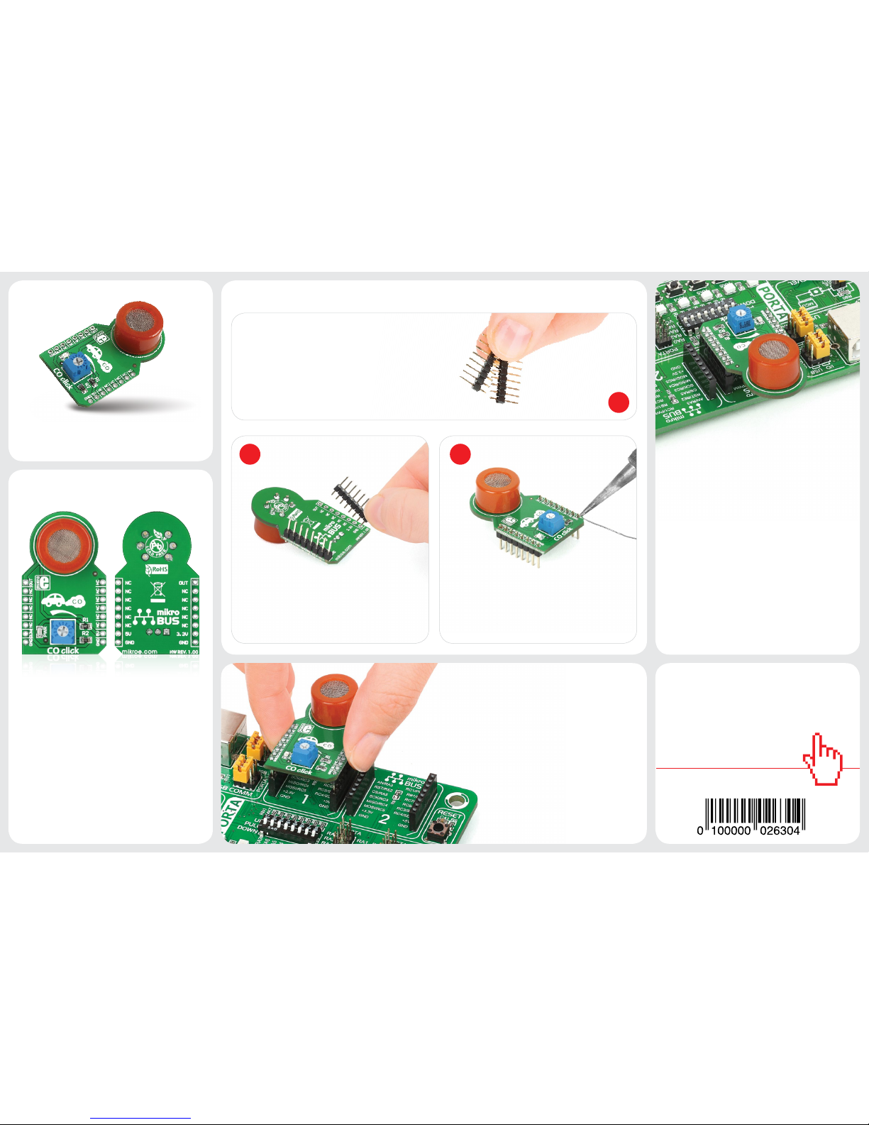
Once you have soldered the headers
your board is ready to be placed into the
desired mikroBUS™ socket. Make sure to
align the cut in the lower-right part of the
board with the markings on the silkscreen
at the mikroBUS™ socket. If all the
pins are aligned correctly, push....
3. Plugging the board in
2 3
2. Soldering the headers
1
4. Essential features
Turn the board upward again. Make sure
to align the headers so that they are
perpendicular to the board, then solder
the pins carefully.
Turn the board upside down so that
the bottom side is facing you upwards.
Place shorter pins of the header into the
appropriate soldering pads.
Before using your click™ board, make sure
to solder 1x8 male headers to both left
and right side of the board. Two 1x8 male
headers are included with the board in
the package.
click
™
BOARD
www.mikroe.com
CO click™ can detect Carbon monoxide
levels in concentrations from 20ppm to
2000ppm. The MQ-7 CO sensor unit has a
sensor layer made of Tin dioxide (SnO2),
an inorganic compound which has lower
conductivity in clean air. The conductivity
increases as the levels of CO rise. CO click™
also contains a potentiometer that lets you
adjust the sensor for the environment. For
precise calibration the sensor needs to
preheat (once powered up, it takes 48h to
reach the right temperature).
CO click Manual
ver. 1.00
CO click
™
CO click™ is a simple solution for adding a
high-sensitivity Carbon monoxide sensor
to your design. The board features an MQ-7
sensor with a Sn02 gas sensing layer, a
calibration potentiometer, a mikroBUS™
host socket, two jumpers and a power
indicator LED. CO click™ communicates
with the target board through mikroBUS™
AN (OUT) line. CO click™ is designed to use
a 5V power supply only.
Page 2
8. Support
MikroElektronika offers free tech sup-
port (www.mikroe.com/support/) until
the end of the product’s lifetime, so if
something goes wrong, we’re ready and
willing to help!
7. Code examples
.com
Once you have done all the necessary preparations, it’s time to get your click™ board up
and running. We have provided examples
for mikroC™, mikroBasic™ and mikroPascal™
compilers on our Libstock website. Just
download them and you are ready to start.
MikroElektronika assumes no responsibility or liability for any errors or inaccuracies that may appear in the present document.
Specication and information contained in the present schematic are subject to change at any time without notice. Copyright © 2014 MikroElektronika. All rights reserved.
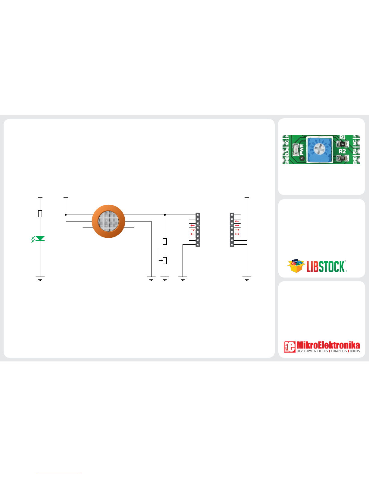
5. CO click™ board schematic
VCC
R1
2K2
VCC
R2
470
VCC
AN
RST
CS
SCK
MOSI
MISO
+3.3V
GND
PWM
INT
RX
TX
SCL
SDA
+5V
GND
MIKROBUS DEVICE CONN.
Analog output
PWR
B
H
B
A
H
A
MQ-7
P1
10K
6. Calibration potentiometer
To calibrate CO click™ for optimum performance, use the on-board potentiometer to
adjust the Load Resistance of the sensor
circuit.
 Loading...