


mikromedia 4 for STM32 CAPACITIVE U S E R M A N U A L
USER MANUAL
for STM32 CAPACITIVE
P A G E 1

Thank you for choosing Mikroe!
We present you the ultimate multimedia solution for embedded development.
Elegant on the surface, yet extremely powerful on the inside, we have designed it to inspire outstanding achievements.
And now, it’s all yours.
Enjoy premium.

Table of contents
Introduction 5
1.Key microcontroller features 6
1.1 MCU programming/debugging 8
1.2 MCU reset 8
2. Power supply unit 10
2.1 Detailed description 11
2.2 Voltage reference 11
2.3 PSU connectors 12
2.4 Power redundancy & UPS 15
2.5 Powering up the board 15
3. Capacitive display 16
4. Data storage 18
4.1 microSD card slot 18
4.2 External flash storage 18
5. Connectivity 19
5.2 RF 20
5.3 USB 21
5.4 1x26 pin headers 22
6. Sound-related peripherals 24
6.1 Piezo buzzer 24
6.2 Audio CODEC 25
6.3 Audio connectors 25
7. Sensors and other peripherals 26
7.1 Ambient light sensor 26
7.2 Digital motion sensor 27
7.3 IR receiver module 27
7.4 RGB LED 27
7.5 Temperature sensor 28
7.6 Real-time clock (RTC) 28
What’s next 30
5.1 Ethernet 19
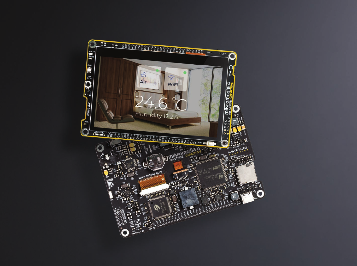

mikromedia 4 for STM32 CAPACITIVE is a compact
USB, Ethernet, RF connectivity options, digital motion
development board designed as a complete solution for
the rapid development of multimedia and GUI-centric
applications. By featuring a 4.3” capacitive touch screen
driven by the powerful graphics controller that can display
the 24-bit color palette (16.7 million colors), along with a
DSP-powered embedded sound CODEC IC, represents a
perfect solution for any type of multimedia application.
At its core, there is a powerful 32-bit STM32F407ZGT6 or
STM32F746ZGT6 microcontroller (referred to as “host MCU”
in the following text), produced by STMicroelectronics,
which provides sufficient processing power for the most
demanding tasks, ensuring fluid graphical performance and
glitch-free audio reproduction.
However, this development board is not limited to
multimedia-based applications only: mikromedia 4 for STM32
sensor, piezo-buzzer, battery charging functionality, SD-
Card reader, RTC, and much more, expanding its use beyond
the multimedia. Two standardized 1x26 pin headers expose
the available MCU pins to the user, adding another layer of
expandability. By using mikromedia 4 shield, connectivity
can be further expanded with several mikroBUS
™
sockets,
additional connectors, peripherals, and so on.
The usability of mikromedia 4 does not end with its ability
to accelerate the prototyping and application development
stages: it is designed as the complete solution which can
be implemented directly into any project, with no additional
hardware modifications required. Four mounting holes
(3.2mm / 0.126”) at all four corners allow simple installation
with mounting screws. For most applications, a nice stylish
casing is all that is needed to turn the mikromedia 4
development board into a fully functional, high-performance,
CAPACITIVE (“mikromedia 4” in the following text) features
feature-rich design.
1. Key microcontroller features
APB2 84MHz
3 x ADC
temperature sensor
1 x SPI
2 x USART
3 x TIMER 16-bit
2 x TIM/PWM 16-bit
SDIO/MMC
2 x CAN
3 x I2C
2 x SPI
2 x UART
2 x USART
5 x TIMER 16-bit
2 x TIMER 32-bit
APB1 42MHz
2 x DAC
2 x TIMER 16-bit
WWDG
RTC
IWDG
SRAM 176 KB
FLASH 1MB
EXT. MEM. CONTR
DMA 2
ETH. MAC 10/100
JTAG & SW
USB OTG FS
CAM. INTERFACE
RNG
DMA 1
SRAM 16KB
USB OTG HS
POWER / RESET
AHB BUS - MATRIX
GPIO PORT
(A,B,C,D,E,F,G,H,I)
ARM
Cortex ™-M4
STM32F 407ZG
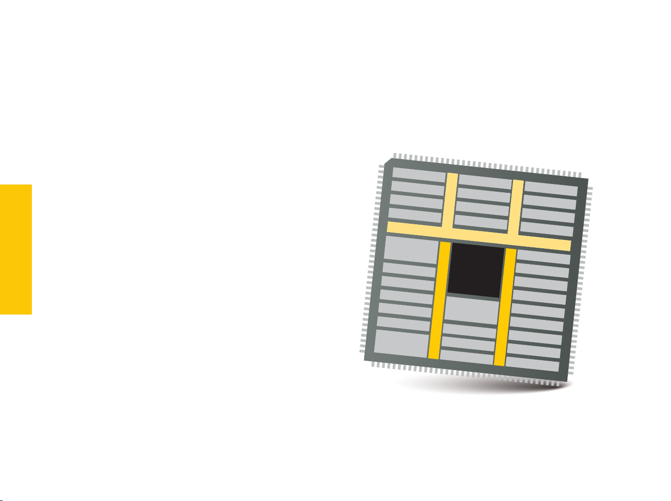
At its core, mikromedia 4 for STM32 CAPACITIVE uses the STM32F407ZGT6 or STM32F746ZGT6 MCU.
STM32F407ZGT6 is the 32-bit RISC ARM® Cortex®-M4 core.
This MCU is produced by STMicroelectronics, featuring a
dedicated floating-point unit (FPU), a complete set of DSP
functions, and a memory protection unit (MPU) for elevated
application security. Among many peripherals available on
the host MCU, key features include:
∫ 1 MB of Flash memory
STM32F407ZGT6
∫ 192 + 4 KB of SRAM (including 64 KB of Core Coupled Memory)
∫ Adaptive real-time accelerator (ART Accelerator
allowing 0-wait state execution from Flash memory
∫ Operating frequency up to 168 MHz
P A G E 6
∫ 210 DMIPS / 1.25 DMIPS/MHz (Dhrystone 2.1)
For the complete list of MCU features, please refer to the
STM32F407ZGT6 datasheet
™
)
Figure 1: STM32F407ZGT6 MCU block schematic
mikromedia 4 for STM32 CAPACITIVE U S E R M A N U A L
APB2 84MHz
3 x ADC
temperature sensor
4 x SPI
2 x USART
3 x TIMER 16-bit
2 x TIM/PWM 16-bit
SDIO/MMC
2 x CAN
4 x I2C
2 x SPI
4 x UART
2 x USART
5 x TIMER 16-bit
2 x TIMER 32-bit
APB1 42MHz
2 x DAC
3 x TIMER 16-bit
WWDG
RTC
IWDG
SRAM 240 KB
FLASH 1MB
EXT. MEM. CONTR
DMA 2
ETH. MAC 10/100
JTAG & SW
USB OTG FS
CAM. INTERFACE
RNG
DMA 1
SRAM 16KB
USB OTG HS
POWER / RESET
AHB BUS - MATRIX
GPIO PORT
(A,B,C,D,E,F,G,H,I)
ARM
Cortex ™-M7
STM32F 746ZGT6
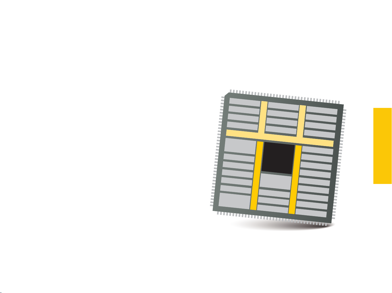
STM32F746ZGT6 is the 32-bit RISC ARM® Cortex®-M7 core.
This MCU is produced by STMicroelectronics, featuring a
dedicated floating-point unit (FPU), a complete set of DSP
functions, and a memory protection unit (MPU) for elevated
application security. Among many peripherals available on
the host MCU, key features include:
∫ 1 MB Flash memory
∫ 320 KB of SRAM
∫ Adaptive real-time accelerator (ART Accelerator
allowing 0-wait state execution from Flash memory
∫ Operating frequency up to 216 MHz
∫ 462 DMIPS / 2.14 DMIPS/MHz (Dhrystone 2.1)
For the complete list of MCU features, please refer to the
STM32F746ZGT6 datasheet
mikromedia 4 for STM32 CAPACITIVE U S E R M A N U A L
MCUs FEATURES
™
)
P A G E 7
Figure 2: STM32F746ZGT6 MCU block schematic
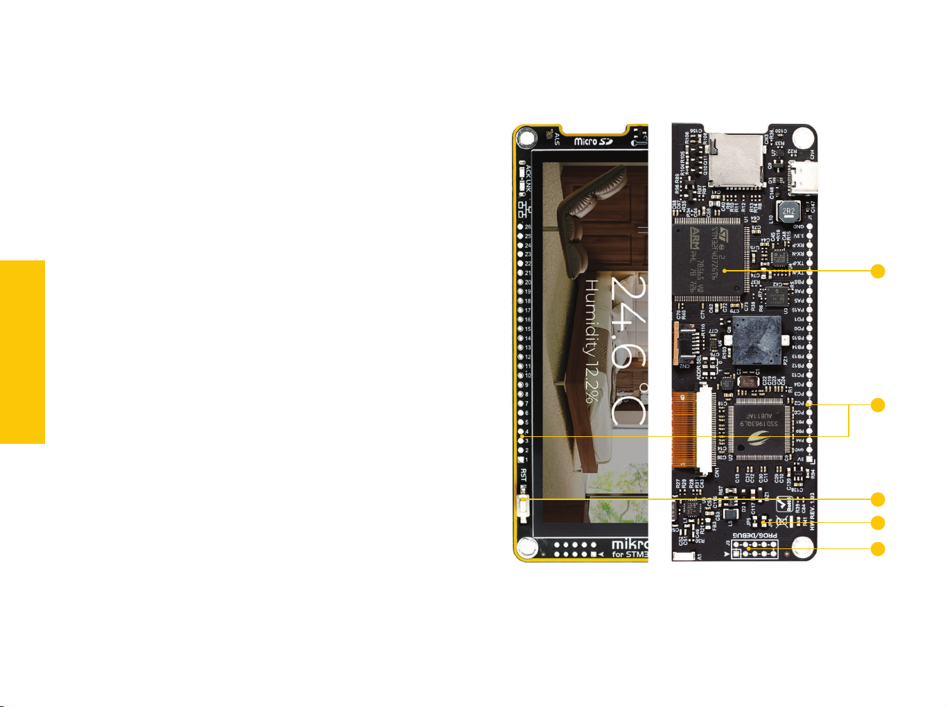
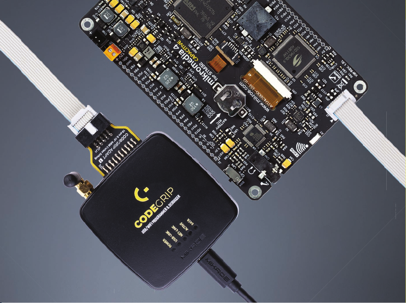
1.1 Microcontroller programming/debugging
The host MCU can be programmed and debugged over the JTAG/SWD
compatible 2x5 pin header (2), labeled as PROG/DEBUG. This header
allows an external programmer (e.g. CODEGRIP or mikroProg) to be used.
To enable the JTAG interface, two SMD jumpers labeled as JP5 and JP6 (3)
must be populated. These jumpers are unpopulated by default, optimizing
the pin count so that more pins could be used for a large number of
onboard modules and peripherals.
Programming the microcontroller can also be done by using the bootloader
which is preprogrammed into the device by default. All the informations
about the bootloader software can be found on the following page:
www.mikroe.com/mikrobootloader
1
MCUs FEATURES
P A G E 8
1.2 MCU reset
The board is equipped with the Reset button (4), which is located on the
front side of the board. It is used to generate a LOW logic level on the
microcontroller reset pin. The reset pin of the host MCU is also routed to
the pin 1 of the 1x26 pin header (5), allowing an external signal to reset
the device.
5
4
3
2
Figure 2: Front and back partial view
mikromedia 4 for STM32 CAPACITIVE U S E R M A N U A L
mikromedia 4 for STM32 CAPACITIVE U S E R M A N U A L
mikromedia 4
for STM32 CAPACITIVE
U S E R M A N U A L
P A G E 9
mikromedia 4
for STM32 CAPACITIVE
U S E R M A N U A L
2. Power supply unit
The power supply unit (PSU) provides clean and regulated
power, necessary for proper operation of the mikromedia 4
development board. The host MCU, along with the rest of the
peripherals, demands regulated and noise-free power supply.
Therefore, the PSU is carefully designed to regulate, filter,
and distribute the power to all parts of mikromedia 4. It is
equipped with three different power supply inputs, offering all
the flexibility that mikromedia 4 needs, especially when used
on the field or as an integrated element of a larger system. In
the case when multiple power sources are used, an automatic
power switching circuit with predefined priorities ensures that
the most appropriate will be used.
P A G E 10
Figure 3: Power supply unit view
The PSU also contains a reliable and safe battery charging
circuit, which allows a single-cell Li-Po/Li-Ion battery to be
charged. Power OR-ing option is also supported, providing
an uninterrupted power supply (UPS) functionality when an
external or USB power source is used in combination with the
battery.
mikromedia 4 for STM32 CAPACITIVE U S E R M A N U A L
mikromedia 4 for STM32 CAPACITIVE U S E R M A N U A L

2.1 Detailed description
The PSU has a very demanding task of providing power for the host MCU
and all the peripherals onboard, as well as for the externally connected
peripherals. One of the key requirements is to provide enough current,
avoiding the voltage drop at the output. Also, the PSU must be able to
support multiple power sources with different nominal voltages, allowing
switching between them by priority. The PSU design, based on a set of
high-performance power switching ICs produced by Microchip, ensures a
very good quality of the output voltage, high current rating, and reduced
electromagnetic radiation.
At the input stage of the PSU, the MIC2253, a high-efficiency boost regulator
IC with overvoltage protection ensures that the voltage input at the next
stage is well-regulated and stable. It is used to boost the voltage of low-
voltage power sources (a Li-Po/Li-Ion battery and USB), allowing the next
stage to deliver well-regulated 3.3V and 5V to the development board. A set
of discrete components are used to determine if the input power source
requires a voltage boost. When multiple power sources are connected
at once, this circuitry is also used to determine the input priority level:
externally connected 12V PSU, power over USB, and the Li-Po/Li-Ion battery.
The transition between available power sources is designed to provide
uninterrupted operation of the development board.
The next PSU stage uses two MCP16331, highly integrated, high-efficiency,
fixed frequency, step-down DC-DC converters, capable of providing up
to 1.2A. Each of the two buck regulators is used to supply power to the
corresponding power supply rail (3.3V and 5V), throughout the entire
development board and connected peripherals.
2.2 Voltage reference
The MCP1501, a high-precision buffered voltage reference from Microchip
is used to provide a very precise voltage reference with no voltage drift. It
can be used for various purposes: the most common uses include voltage
references for A/D converters, D/A converters, and comparator peripherals
on the host MCU. The MCP1501 can provide up to 20mA, limiting its use
exclusively to voltage comparator applications with high input impedance.
Depending on the specific application, either 3.3V from the power rail,
or 2.048V from the MCP1501 can be selected. An onboard SMD jumper
labeled as REF SEL offers two voltage reference choices:
∫ REF: 2.048V from the high-precision voltage reference IC
∫ 3V3: 3.3V from the main power supply rail
POWER SUPPLY
P A G E 11
mikromedia 4 for STM32 CAPACITIVE U S E R M A N U A L
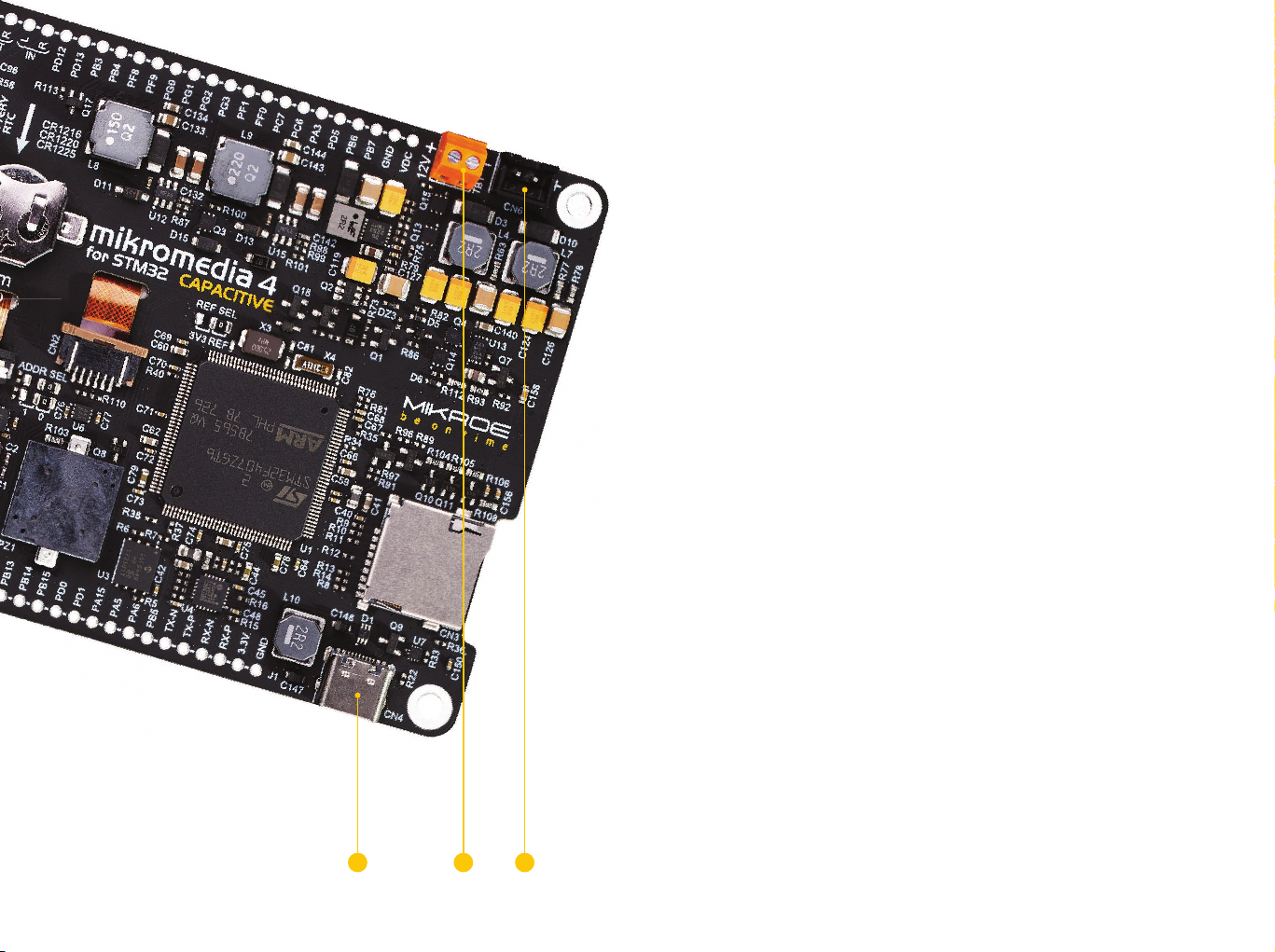
2.3 PSU connectors
As explained, the advanced design of the PSU allows several types of power
sources to be used, offering unprecedented flexibility: when powered by
a Li-Po/Li-Ion battery, it offers an ultimate degree of autonomy. For
situations where the power is an issue, it can be powered by an external
12VDC power supply, connected over the 5.5mm barrel connector or over
the two-pole screw terminal. Power is not an issue even if it is powered
over the USB cable. It can be powered over the USB-C connector, using
power supply delivered by the USB HOST (i.e. personal computer), USB wall
adapter, or a battery power bank.
There are three power supply connectors available, each with its unique
purpose:
∫ CN4: USB-C connector (1)
∫ TB1: Screw terminal for an external 12VDC PSU (2)
∫ CN6: Standard 2.5mm pitch XH battery connector (3)
P A G E 12
Figure 4: Power supply connectors view
2.3.1 USB-C connector
The USB-C connector (labeled as CN4) provides power from the USB host
(typically PC), USB power bank, or USB wall adapter. When powered over the
USB connector, the available power will depend on the source capabilities.
1 32
mikromedia 4 for STM32 CAPACITIVE U S E R M A N U A L

Maximum power ratings, along with the allowed input voltage range in the
case when the USB power supply is used, are given in the table below:
USB power supply
Input Voltage [V] Output Voltage [V]
Max Current [A] Max Power [W]
supply unit can be easily exchanged with another, while its power and
operating characteristics can be decided per application. The development
board allows a maximum current of 1.2A per power rail (3.3V and 5V) when
using an external 12V power supply. The screw terminal is a good choice
when there is no connector installed at the end of the PSU cable.
N O T E
MIN
4.4 5.5
Figure 5: USB power supply table
When using a PC as the power source, the maximum power can be obtained
if the host PC supports the USB 3.2 interface, and is equipped with USB-C
connectors. If the host PC uses the USB 2.0 interface, it will be able to
provide the least power, since only up to 500 mA (2.5W at 5V) is available
in that case. Note that when using longer USB cables or USB cables of low
quality, the voltage may drop outside the rated operating voltage range,
causing unpredictable behavior of the development board.
If the USB host is not equipped with the USB-C connector, a Type A to
Type C USB adapter may be used (included in the package).
MAX
3.3
5
3.3 & 5
1.2
1.2
0.7 & 0.7
3.96
6
5.81
2.3.2 12VDC screw terminal
Maximum power ratings, along with the allowed input voltage range in the
case when the external power supply is used, are given in the table below:
External power supply
Input Voltage [V] Output Voltage [V]
MIN
10.6 14
Figure 6: External power supply table
MAX
3.3
5
3.3 & 5
Max Current [A] Max Power [W]
1.2
1.2
1.2 & 1.2
3.96
6
9.96
POWER SUPPLY
P A G E 13
An external 12V power supply can be connected over the 2-pole screw
terminal (labeled as TB1). When using an external power supply, it is
possible to obtain an optimal amount of power, since one external power
mikromedia 4 for STM32 CAPACITIVE U S E R M A N U A L
When connecting an external power supply over the screw terminal,
make sure that the polarity of the wires is matched with the 12VDC
connector on the development board, according to the marked pins
of screw terminal.
N O T E

mikromedia 4
for STM32 CAPACITIVE
U S E R M A N U A L
2.3.3 Li-Po/Li-Ion XH battery connector
POWER SUPPLY
P A G E 14
P A G E 14
When powered by a single-cell Li-Po/Li-Ion battery, mikromedia 4 offers an
option to be operated remotely. This allows complete autonomy, allowing
it to be used in some very specific situations: hazardous environments,
agricultural applications, etc.
The battery connector is a standard 2.5mm pitch XH connector. It allows
a range of single-cell Li-Po and Li-Ion batteries to be used. The PSU of
mikromedia 4 offers the battery charging functionality, from both the USB
connector and the 12VDC/external power supply. The battery charging
circuitry of the PSU manages the battery charging process, allowing the
optimal charging conditions and longer battery life. The charging process
is indicated by BATT LED indicator, located on the front of mikromedia 4.
The PSU module also includes the battery charger circuit. Depending on the
operational status of the mikromedia 4 development board, the charging
current can be either set to 100mA or 500mA. When the development
board is powered OFF, the charger IC will allocate all available power for the
battery charging purpose. This results in faster charging, with the charging
current set to approximately 500mA. While powered ON, the available
charging current will be set to approximately 100 mA, reducing the overall
power consumption to a reasonable level.
Maximum power ratings along with the allowed input voltage range when
the battery power supply is used, are given in the table below:
Battery power supply
Input Voltage [V] Output Voltage [V]
MIN
MAX
3.3
5
Max Current [A] Max Power [W]
1.2
1.1
3.96
5.5
3.5 4.2
3.3 & 5
Figure 7: Battery power supply table
0.6 & 0.6
4.98
N O T E Using low-quality USB hubs, and too long or low-quality USB cables,
may cause a significant USB voltage drop, which can obstruct the
battery charging process.
mikromedia 4 for STM32 CAPACITIVE U S E R M A N U A L

2.4 Power redundancy and
2.5 Powering up the
uninterrupted power supply (UPS)
The PSU module supports power supply redundancy: it will automatically
switch to the most appropriate power source if one of the power sources
fails or becomes disconnected. The power supply redundancy also allows
for an uninterrupted operation (i.e. UPS functionality, the battery will still
provide power if the USB cable is removed, without resetting mikromedia 4
during the transition period).
mikromedia 4 board
After a valid power supply source is connected (1) in our case with a single-
cell Li-Po/Li-Ion battery, mikromedia 4 can be powered ON. This can be
done by a small switch at the edge of the board, labeled as SW1 (2). By
switching it ON, the PSU module will be enabled, and the power will be
distributed throughout the board. A LED indicator labeled as PWR indicates
that the mikromedia 4 is powered ON.
2
POWER SUPPLY
1
mikromedia 4 for STM32 CAPACITIVE U S E R M A N U A L
Figure 8: Battery power supply connection
P A G E 15

3. Capacitive display
CAPACITIVE DISPLAY
P A G E 16
A high-quality 4.3” TFT true-color display with a capacitive
touch panel is the most distinctive feature of the mikromedia 4.
The display has a resolution of 480 by 272 pixels, and it can
display up to 16.7M of colors (24-bit color depth). The display
of mikromedia 4 features a reasonably high contrast ratio
of 500:1, thanks to 10 high-brightness LEDs used for the
backlighting.
The display module is controlled by the SSD1963 (1)
driver IC from Solomon Systech. This is a powerful graphics
coprocessor, equipped with 1215KB of frame buffer memory.
It also includes some advanced features such as the hardware
accelerated display rotation, display mirroring, hardware
windowing, dynamic backlight control, programmable color
and brightness control, and more.
The capacitive multi-touch panel, based on the FT5216 CTP
graphics
with the host controller. This advanced multi-touch panel
controller supports gestures, including zoom and swipe in all
four directions.
Equipped with high-quality 4.3” display (2) and the multi-
touch controller that supports gestures, mikromedia 4
represents a very powerful hardware environment for
building various GUI-centric Human Machine Interface (HMI)
applications.
controller, allows the development of interactive applications,
offering a touch-driven control interface. The touch panel
controller uses the I2C interface for the communication
mikromedia 4 for STM32 CAPACITIVE U S E R M A N U A L

2
1
Figure 9: Display and SSD1963 view

mikromedia 4
for STM32 CAPACITIVE
U S E R M A N U A L
Figure 9: MicroSD card slot view
4. Data storage
The mikromedia 4 development board is equipped with two
types of storage memory: with a microSD card slot and a
Flash memory module.
DATA STORAGE
4.1 microSD card slot 4.2 External flash storage
P A G E 18
P A G E 18
The microSD card slot (1) allows storing large amounts of data externally,
on a microSD memory card. It uses the Secure digital input/output
interface (SDIO) for communication with the MCU. The microSD card
detection circuit is also provided on the board. The microSD card is the
smallest SD Card version, measuring only 5 x 11 mm. Despite its small
size, it allows tremendous amounts of data to be stored on it. In order to
read and write to the SD Card, a proper software/firmware running on the
host MCU is required.
12
mikromedia 4 is equipped with the SST26VF064B Flash memory (2). The
Flash memory module has a density of 64 Mbits. Its storage cells are
arranged in 8-bit words, resulting in 8Mb of non-volatile memory in total,
available for various applications. The most distinctive features of the
SST26VF064B Flash module are its high speed, very high endurance, and
very good data retention period. It can withstand up to 100,000 cycles, and
it can preserve the stored information for more than 100 years. It also uses
the SPI interface for the communication with the MCU.
mikromedia 4 for STM32 CAPACITIVE U S E R M A N U A L
mikromedia 4 for STM32 CAPACITIVE U S E R M A N U A L

mikromedia 4
for STM32 CAPACITIVE
U S E R M A N U A L
5. Connectivity
mikromedia 4 offers a huge number of connectivity options.
It includes support for the Ethernet, RF and USB (HOST/
DEVICE). Besides those options, it also offers two 1x26 pin
headers, which are used to directly access the MCU pins.
5.1 Ethernet
Ethernet is a popular computer networking technology for local area
networks (LAN). Systems communicating over Ethernet divide a stream of
data into individual packets, known as frames. Each frame contains source
and destination addresses and error-checking data so that damaged data
can be detected and re-transmitted. This makes the Ethernet protocol very
popular for communication over longer distances or in noisy environments.
The host MCU features an integrated Ethernet peripheral module, which
contains the entire communication stack on-chip. The physical layer is
provided by the LAN8720A (1), an RMII 10/100 Mbit Ethernet PHY IC from
Microchip. This IC has many useful features, including flexPWR® technology
with a flexible power management architecture and a support for various
low-power modes, compliance with ISO 802-3/IEEE and IEEE802.3/802.3u
frame formats, loopback modes support, auto-negotiation, automatic
polarity detection and correction, link status change wake-up detection,
vendor specific register functions, support for the reduced pin count RMII
interface, and much more.
It allows mikromedia 4 to connect to an Ethernet network over its shield as
TX and RX lines are routed to the 1x26 pin headers (2). mikromedia 4 is
equipped with two LED indicators, which are located on the front side. They
are used to signal status and data traffic.
12
Figure 10: 1x26 pins-header view
P A G E 19
mikromedia 4 for STM32 CAPACITIVE U S E R M A N U A L
mikromedia 4 for STM32 CAPACITIVE U S E R M A N U A L

5.2 RF
mikromedia 4 offers communication over the world-wide ISM radio band.
The ISM band covers a frequency range between 2.4GHz and 2.4835GHz.
This frequency band is reserved for industrial, scientific, and medical use
(hence the ISM abbreviation). In addition, it is globally available, making it
a perfect alternative to WiFi, when the M2M communication over a short
distance is required.
mikromedia 4 uses the nRF24L01+ (1), a single-chip 2.4GHz transceiver
with an embedded baseband protocol engine, produced by Nordic
Semiconductors. It is a perfect solution for ultra-low power wireless
applications. This transceiver relies on the GFSK modulation, allowing data
rates in the range from 250 kbps, up to 2 Mbps. The GFSK modulation
is the most efficient RF signal modulation scheme, reducing the required
bandwidth, thus wasting less power. The nRF24L01+ also features a
CONNECTIVITY
P A G E 20
proprietary Enhanced ShockBurst
Besides other functionalities, it offers a 6-channel MultiCeiver
which allows using the nRF24L01+ in a star network topology. The
nRF24L01+ uses the SPI interface to communicate with the host MCU.
Along the SPI lines, it uses additional GPIO pins for the SPI Chip Select,
Chip Enable, and for the interrupt. The RF section of the mikromedia 4
also features a small chip antenna (2), reducing the need for additional
hardware components.
™
, a packet-based data link layer.
™
feature,
12
mikromedia 4 for STM32 CAPACITIVE U S E R M A N U A L

mikromedia 4
for STM32 CAPACITIVE
U S E R M A N U A L
Figure 11: RF and WiFi view
5.3 USB
The host MCU is equipped with the USB peripheral module, allowing
simple USB connectivity. USB (Universal Serial Bus) is a very popular
industry standard that defines cables, connectors, and protocols used
for communication and power supply between computers and other
devices. mikromedia 4 supports USB as HOST/DEVICE modes, allowing
the development of a wide range of various USB-based applications. It
is equipped with the USB-C connector, which offers many advantages,
compared to earlier types of USB connectors (symmetrical design, higher
current rating, compact size, etc).
The USB mode selection is done using a monolithic controller IC. This IC
provides Configuration Channel (CC) detection and indication functions.
To set up mikromedia 4 as the USB HOST, the USB PSW pin should be set to
a LOW logic level (0) by the MCU. If set to a HIGH logic level (1), mikromedia 4 acts
as a DEVICE. While in HOST mode, mikromedia 4 provides power over the
USB-C connector (3) for the attached DEVICE. The USB PSW pin is driven
by the host MCU, allowing the software to control the USB mode.
The USB ID pin is used to detect the type of the device attached to the USB
port, according to the USB OTG specifications: the USB ID pin connected to
GND indicates a HOST device, while the USB ID pin set to a high impedance
state (HI-Z) indicates that the connected peripheral is a DEVICE.
CONNECTIVITY
P A G E 21
P A G E 21
mikromedia 4 for STM32 CAPACITIVE U S E R M A N U A L
mikromedia 4 for STM32 CAPACITIVE U S E R M A N U A L
3
mounted to another USB HOST (such as PC).
N O T EWhen mikromedia 4 is working in USB HOST mode, it must not be

5.4 1x26 pin headers
Most of the host MCU pins are routed to the two 1x26 pin headers (1), making them available for further connectivity. In addition to MCU pins, some
additional peripheral pins are also routed to this header.
Besides the ability to connect various external devices and peripherals by using wire jumpers, these pins also allow using shields with the additional
™
mikroBUS
including motor drivers, buck/boost converters, sensors, and much more. For the complete list of all the Click boards
link: www.mikroe.com/click
sockets. This allows mikromedia 4 to be interfaced with a huge base of different Click boards™ adding many different functionalities and options,
™
in our offer, please visit the following
CONNECTIVITY
PROGRAMMING
P A G E 22
P A G E 22
5V pwr.
Ground
Analog
GPIO
SPI2
CAN
SPI1
ETH
3.3V pwr.
Ground
5V
GND
PA4
PB0
PB1
PC0
PC2
PC3
PC13
PG4
PB12
PB13
PB14
PB15
PD0
PD1
PA15
PA5
PA6
PB5
TX-N
TX-P
RX-N
RX-P
3.3V
GND
52.
51.
50.
49.
48.
47.
46.
45.
44.
43.
42.
41.
40.
39.
38.
37.
36.
35.
34.
33.
32.
31.
30.
29.
28.
27.
PWM Interrupt I2C UART Analog lines SPI
Figure 13: 1x26 pin header view
26. RST
25. 3.3V
24. L
23. R
22. L
21. R
20. PD12
19. PD13
18. PB3
17. PB4
16. PF8
15. PF9
14. PG0
13. PG1
12. PG2
11. PG3
10. PF1
9. PF0
8. PC7
7. PC6
6. PA3
5. PD5
4. PB6
3. PB7
2. GND
1. VDC
mikromedia 4 for STM32 CAPACITIVE U S E R M A N U A L
mikromedia 4 for STM32 CAPACITIVE U S E R M A N U A L
Reset
3.3V pwr.
Audio OUT
Audio IN
PWM
INTERRUPT
I2C2
UART2
UART1
I2C1
Ground
VCC-EXT

mikromedia 4
for STM32 CAPACITIVE
U S E R M A N U A L
1
CONNECTIVITY
P A G E 23
mikromedia 4 for STM32 CAPACITIVE U S E R M A N U A L
Figure 13: mikromedia 4 back view
1

mikromedia 4
for STM32 CAPACITIVE
U S E R M A N U A L
6. Sound-related peripherals
By offering a pair of sound-related peripherals, mikromedia 4
rounds-up its multimedia concept. It features a piezo-buzzer,
which is extremely easy to program but can produce only the
simplest sounds, useful only for alarms or notifications.
The second audio option is the powerful VS1053B IC (1). It is
an Ogg Vorbis/MP3/AAC/WMA/FLAC/WAV/MIDI audio decoder,
and a PCM/IMA ADPCM/Ogg Vorbis encoder, both on a single
chip. It features a powerful DSP core, high-quality A/D and
AUDIO
D/A converters, stereo headphones driver capable of driving
a 30Ω load, zero-cross detection with the smooth volume
change, bass and treble controls, and much more.
2
6.1 Piezo buzzer
P A G E 24
P A G E 24
A piezo buzzer (2) is a simple device capable of reproducing sound. It
is driven by a small pre-biased transistor. The buzzer can be driven by
applying a PWM signal from the MCU at the base of the transistor: the
pitch of the sound depends on the frequency of the PWM signal, while the
volume can be controlled by changing its duty cycle. Since it is very easy to
program, it can be very useful for simple alarms, notifications, and other
types of simple sound signalization.
Figure 14: mikromedia 4 back view
mikromedia 4 for STM32 CAPACITIVE U S E R M A N U A L
mikromedia 4 for STM32 CAPACITIVE U S E R M A N U A L

mikromedia 4
for STM32 CAPACITIVE
U S E R M A N U A L
decode audio streams independently while performing DSP-related tasks
in parallel. The VS1053B has several key features that make this IC very
popular choice when it comes to audio processing.
By offering high-quality hardware compression (encoding), the VS1053B
allows the audio to be recorded taking up much less space compared to
the same audio information in its raw format. In combination with high-
quality ADCs and DACs, headphones driver, integrated audio equalizer,
volume control, and more, it represents an all-around solution for any
type of audio application. Along with the powerful graphics processor, the
VS1053B audio processor completely rounds-up the multimedia aspects
of the mikromedia 4 development board.
6.3 Audio connectors
The mikromedia 4 board is equipped with the 3.5mm four-pole headphones
jack (3), allowing to connect a headset with a microphone. Two line-level
audio outputs are also available over the 1x26 pin header (4).
AUDIO
6.2 Audio CODEC
Resource-demanding and complex audio processing tasks can be
offloaded from the host MCU by utilizing a dedicated audio CODEC IC,
labeled as VS1053B (1). This IC supports many different audio formats,
commonly found on various digital audio devices. It can encode and
mikromedia 4 for STM32 CAPACITIVE U S E R M A N U A L
mikromedia 4 for STM32 CAPACITIVE U S E R M A N U A L
4
15 3
The microphone input from the 3.5mm four-pole headset jack is
multiplexed with two line-level audio inputs. By using an SMD jumper (5)
located near the headphone jack, it is possible to select which audio input
will be used by the VS1053B. The choices are:
LIN: two line-level inputs form the 1x26 pin header
MIC: electret microphone, connected over the 3.5mm headphone jack
P A G E 25
P A G E 25

mikromedia 4
for STM32 CAPACITIVE
U S E R M A N U A L
7. Sensors and other peripherals
OTHER PERIPHERALS
P A G E 26
P A G E 26
A set of additional onboard sensors and devices adds yet
another layer of usability to the mikromedia 4 development
board.
7.1 Ambient light sensor
An ambient light sensor (ALS) (1) can be used for dimming the screen
intensity in low-light conditions, allowing for the lower power consumption.
It can also be used to detect the proximity and turn on the screen or
increase its brightness when the user approaches. The ALS sensor on the
mikromedia 7 can be utilized in many ways. The LTR-329ALS-01 sensor
uses the I2C interface to communicate with the host MCU.
7.2 Digital motion sensor
The FXOS8700CQ, an advanced integrated 3-axis accelerometer and 3-axis
magnetometer, can detect many different motion-related events, including the
orientation event detection, freefall detection, shock detection, as well as tap,
and double-tap event detection. These events can be reported to the host MCU
over two dedicated interrupt pins, while the data transfer is performed over the
I2C communication interface. The FXOS8700CQ sensor can be very useful for
display orientation detection. It can also be used to turn mikromedia 4 into a
complete 6-axis e-compass solution. The I2C slave address can be changed by
using two SMD jumpers grouped under the ADDR SEL label (2).
Figure 15: mikromedia 4 partial front view
4 3 1
mikromedia 4 for STM32 CAPACITIVE U S E R M A N U A L
mikromedia 4 for STM32 CAPACITIVE U S E R M A N U A L

mikromedia 4
for STM32 CAPACITIVE
U S E R M A N U A L
7.3 IR receiver module
An infrared (IR) receiver (3) with the integrated PIN diode and a
demodulation section allows simple control over an IR remote controller
to be implemented. Thanks to the integrated demodulation section,
the captured IR signal from the remote controller can be directly used
by the host MCU. The TSOP6238 IR receiver module allows very simple
implementation of the IR remote control option, for any application.
mikromedia 4 for STM32 CAPACITIVE U S E R M A N U A L
mikromedia 4 for STM32 CAPACITIVE U S E R M A N U A L
7.4 RGB LED
Figure 16: mikromedia 4 partial back view
2
A high-brightness RGB LED (4) option can be used to provide visual feedback
in a very simple way. There are three pre-biased bipolar transistors on
each of the RGB LED segments (red, blue, and green), allowing them to be
individualy dimmed by PWM pins of the host MCU. Thanks to its reasonably
low power consumption compared to a TFT display, RGB LED can be used
in many situations when only simple visual feedback is required (e.g.
signaling that the application is in the Stand-By mode)
OTHER PERIPHERALS
P A G E 27
P A G E 27

7.5 Temperature sensor
The MCP9700A, an integrated low-power linear active thermistor allows
measurement of the ambient temperature. This sensor provides an analog
voltage which changes linearly with the applied temperature. This voltage
can be sampled by the A/D converter on the host MCU, making it available
for various user applications. The MCP9700A can measure the temperature
within the range from -40°C to +125°C, but the actual measurement range
is limited by the thermal endurance of the mikromedia 4 board itself.
Nevertheless, having a thermal sensor on board is very useful, allowing the
development of thermal monitoring applications, weather stations, and
similar.
7.6 Real-time clock (RTC)
RAPID
DEVELOPMENT
OF MULTIMEDIA
OTHER PERIPHERALS
P A G E 28
The host MCU contains a real-time clock peripheral module (RTC). The
RTC peripheral uses a separate power supply source, typically a battery. To
allow continuous tracking of time, mikromedia 4 is equipped with a button
cell battery that maintains RTC functionality even if the main power supply
is OFF. Extremely low power consumption of the RTC peripheral allows
these batteries to last very long. The mikromedia 4 development board is
equipped with the button cell battery holder, compatible with the CR1216,
CR1220 and CR1225 button cell battery types, allowing it to include a real
time clock within the applications.
AND GUI-CENTRIC
APPLICATIONS
mikromedia 4 for STM32 CAPACITIVE U S E R M A N U A L


What’s Next?
You have now completed the journey through each and every feature of mikromedia 4 for STM32 CAPACITIVE development board.
You got to know its modules and organization. Now you are ready to start using your new board. We are suggesting several steps
which are probably the best way to begin.
1 COMPILERS
Easy programming, clean interface, powerful debugging, great support - our
compilers come in three different flavors: mikroC PRO for ARM, mikroBASIC
PRO for ARM and mikroPASCAL PRO for ARM, offering a complete rapid
embedded development solution for these 3 major programming languages.
www.mikroe.com/compilers/compilers-arm
2 PROJECTS
Once you have chosen your compiler, and since you already got the board, you
are ready to start writing your first projects. We have equipped our compilers
with dozens of examples that demonstrate the use of each and every feature
of the mikromedia 4 for STM32 CAPACITIVE development board. This makes an
excellent starting point for future custom projects. Just load the example, read
well commented code, and see how it works on hardware.
3 COMMUNITY
We invite you to join thousands of users of Mikroe development tools. You will
find useful projects and tutorials and get help from a large user community.
If you want to download free projects and libraries, or share your own code,
please visit the Libstock website. With user profiles, you can get to know other
programmers, and subscribe to receive notifications on their code.
www.libstock.mikroe.com
4 SUPPORT
Mikroe offers free Tech Support to the end of its life span, so if anything goes
wrong, we are ready and willing to help. We know how important it is to be able
to rely on someone in the moments when we are stuck with our projects for
any reason, or facing a deadline. This is why our Support Department, as one
of the pillars upon which our company is based, now also offers the Premium
Technical Support to business users, ensuring even shorter time-frame for
solutions. www.mikroe.com/support

D I S C L A I M E R
All the products owned by MikroElektronika are protected by copyright law and international copyright treaty. Therefore, this manual is to be treated as any other copyright
material. No part of this manual, including product and software described herein, must be reproduced, stored in a retrieval system, translated or transmitted in any form or
by any means, without the prior written permission of MikroElektronika. The manual PDF edition can be printed for private or local use, but not for distribution. Any modification
of this manual is prohibited.
MikroElektronika provides this manual ‘as is’ without warranty of any kind, either expressed or implied, including, but not limited to, the implied warranties or conditions of
merchantability or fitness for a particular purpose.
MikroElektronika shall assume no responsibility or liability for any errors, omissions and inaccuracies that may appear in this manual. In no event shall MikroElektronika, its
directors, officers, employees or distributors be liable for any indirect, specific, incidental or consequential damages (including damages for loss of business profits and
business information, business interruption or any other pecuniary loss) arising out of the use of this manual or product, even if MikroElektronika has been advised of the
possibility of such damages. MikroElektronika reserves the right to change information contained in this manual at any time without prior notice, if necessary.
HIGH RISK ACTIVITIES
The products of MikroElektronika are not fault – tolerant nor designed, manufactured or intended for use or resale as on – line control equipment in hazardous
environments requiring fail – safe performance, such as in the operation of nuclear facilities, aircraft navigation or communication systems, air traffic control, direct life
support machines or weapons systems in which the failure of Software could lead directly to death, personal injury or severe physical or environmental damage (‘High
Risk Activities’). MikroElektronika and its suppliers specifically disclaim any expressed or implied warranty of fitness for High Risk Activities.
TRADEMARKS
The MikroElektronika name and logo, the MikroElektronika logo, mikroC, mikroBasic, mikroPascal, mikroProg, mikromedia, Fusion, Click boards™ and mikroBUS™ are trademarks
of MikroElektronika. All other trademarks mentioned herein are property of their respective companies.
All other product and corporate names appearing in this manual may or may not be registered trademarks or copyrights of their respective companies, and are only used for
identification or explanation and to the owners’ benefit, with no intent to infringe.
Copyright © MikroElektronika, 2019, All Rights Reserved.

mikromedia 4 for STM32 CAPACITIVE
Manual v.100
If you want to learn more about our products, please visit our website at www.mikroe.com
If you are experiencing some problems with any of our products or just need additional information,
please place your ticket at www.mikroe.com/support
If you have any questions, comments or business proposals, do not hesitate to contact us at office@mikroe.com
 Loading...