

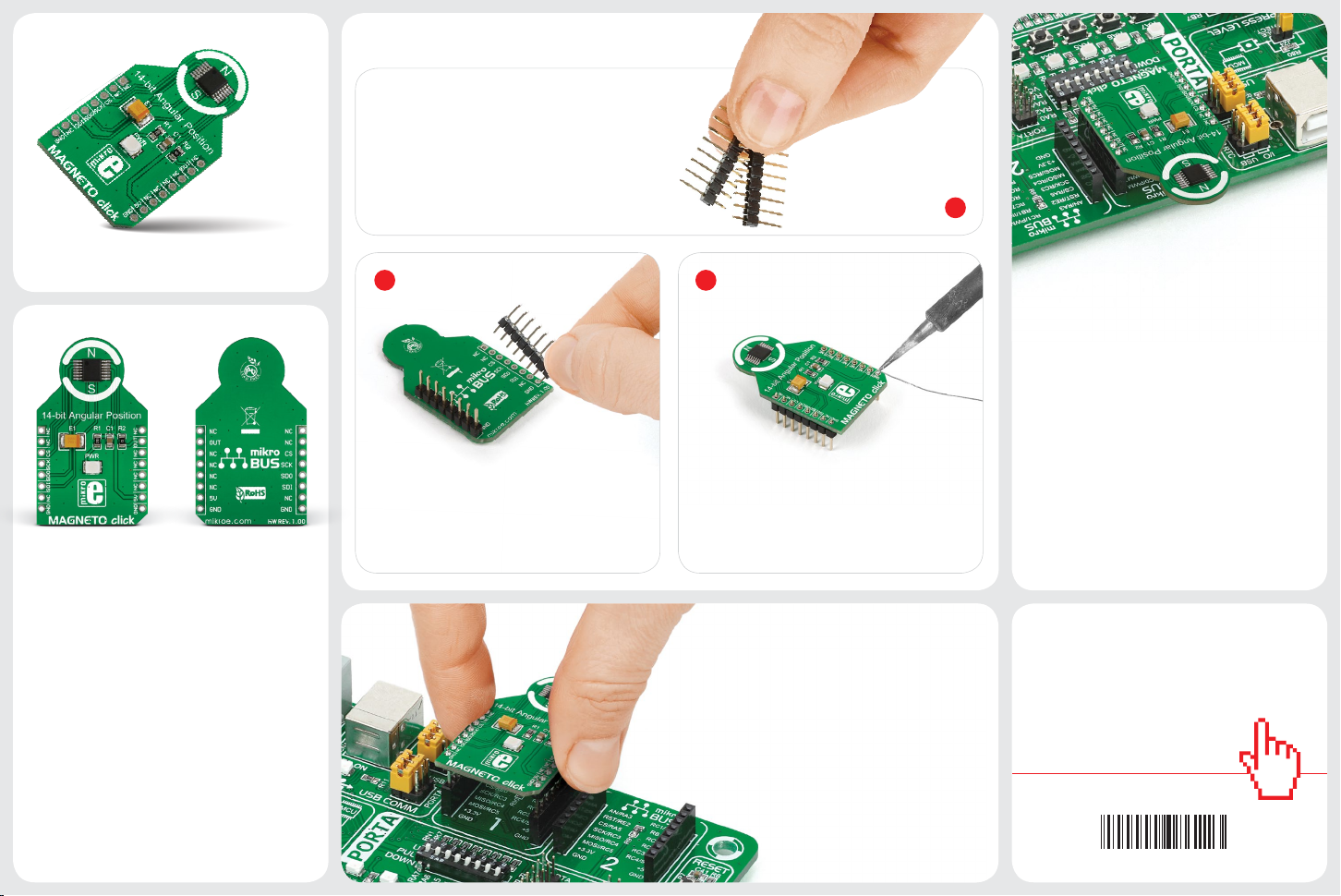
2. Soldering the headers
0100000086223
™
Before using your click board
to solder 1x8 male headers to both left and
right side of the board. Two 1x8 male headers
are included with the board in the package.
, make sure
1
MAGNETO click
1. Introduction
Magneto click carries an AS5048A
contactless magnetic angle position
sensor. The sensing circuitry relies on the
Hall Eect to detect the vector of a nearby
magnetic eld in a 360º two-dimensional
plane parallel to the surface of the chip.
Magneto click communicates with the
target MCU through the mikroBUS™ SPI
interface (CS, CLK, MISO, MOSI), with an
additional PWM output. Magneto click is
designed to use a 5V power supply only.
2 3
Turn the board upside down so that
the bottom side is facing you upwards.
Place shorter pins of the header into the
appropriate soldering pads.
Turn the board upward again. Make sure
to align the headers so that they are
perpendicular to the board, then solder the
pins carefully.
3. Plugging the board in
Once you have soldered the headers your
board is ready to be placed into the desired
mikroBUS™ socket. Make sure to align the cut
in the lower-right part of the board with the
markings on the silkscreen at the mikroBUS™
socket. If all the pins are aligned
correctly, push the board all the
way into the socket.
4. Essential features
Magneto click is intended for use with a
rotating bipolar magnetic target. Those
include setting up a digital potentiometer,
sensing motor rotation, or in automotive
applications for power steering and throttle
sensing. AS5048A delivers precise angle
measurements down to 0.05º in 14-bit
resolution. Its accuracy is not impeded (up to
a point) by misalignment, air gap variations,
temperature variations, even stray magnetic
elds. The PWM outputs the absolute position
information. Additionally, the magnet’s zero
position is programmable (via SPI).
click
™
BOARDS
www.mikroe.com
MAGNETO click Manual v100
AN
RST
CS
SCK
MOSI
MISO
+3.3V
GND
PWM
INT
RX
TX
SCL
SDA
+5V
GND
MIKROBUS_DEVICE_CONN.
R1
2K2
PWR
GND
VCC
GND GND
C1
100nF
E1
10uF
1
2
3
4
5
6
7 8
9
10
11
12
13
14
CSn
CLK
MISO
MOSI
TEST
TEST
TEST
TEST
TEST
PWM
GND
VDD3V
VDD5V
TEST
U1
AS5048A
CS
CLK
MISO
MOSI
VCC
MOSI
MISO
CLK
CS
VCC
R2
0R
PWM_OUT
PWM_OUT
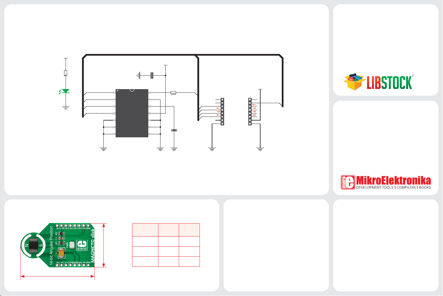
5. Schematic
8. Code examples
6. Dimensions
42.9 mm / 1690 mils
25.4 mm / 1000 mils
LENGTH
WIDTH
HEIGHT*
* without headers
mm mils
42.9 1690
25.4 1000
3.9 154
7. Magneto click alternatives
If high accuracy and resolution is not required
for your application, an alternative 360º
degree sensor is available with Angle click.
www.mikroe.com/click
Once you have done all the necessary
preparations, it’s time to get your click board
™
up and running. We have provided examples
for mikroC™, mikroBasic™ and mikroPascal™
compilers on our Libstock website. Just
download them and you are ready to start.
.com
9. Support
MikroElektronika oers free tech support
(www.mikroe.com/support) until the end of
the product’s lifetime, so if something goes
wrong, we’re ready and willing to help!
10. Disclaimer
MikroElektronika assumes no responsibility
or liability for any errors or inaccuracies
that may appear in the present document.
Specication and information contained in
the present schematic are subject to change
at any time without notice.
Copyright © 2016 MikroElektronika.
All rights reserved.
 Loading...