

Page 1
Go to Cloud
(G2C) click
U S E R M A N U A L
The WiFi IoT gateway Click board™ which
connects your IoT devices with the Click
Cloud service provided by MikroElektronika.
Simple and reliable.
Page 2

To our valued customers
I want to express my thanks to you for being interested in our products
and for having confidence in MikroElektronika.
The primary aim of our company is to design and produce high quality
electronic products and to constantly improve the performance thereof in
order to better suit your needs.
Nebojsa Matic
General Manager
Page 2
Page 3

Table of Contents
Introduction to Go to Cloud (G2C) click 4
mikroBUS™ pins 7
Onboard indicators and LED indicators 8
Pins description 8
UART interface – configuration 9
Boot-up sequence 10
Firmware update 12
Page 4

Introduction to Go to Cloud (G2C) click
Go to Cloud (G2C) click is composed of two main components:
∫ MK64FN1M0VDC12, a 32-bit ARM® Cortex® M4 microcontroller, from NXP
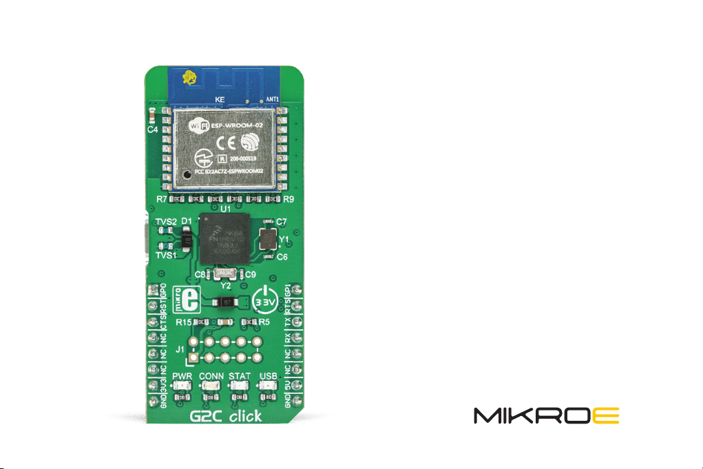
∫ ESP WROOM-02, a Wi-Fi connector module, from Espressif systems
The ESP-WROOM-02 is used as the connector module which can establish a link with the Click cloud service over the Internet.
It is an all-in-one solution, with the complete Wi-Fi stack on-board, which allows a very simple operation. This feature, along
with the proven reliability, small form-factor, and low count of components it requires, makes the ESP WROOM-02 module
an ideal solution for using it on the Go to Cloud (G2C) click.
The ESP-WROOM-02 module uses the UART communication interface, and it can be controlled by using simple AT
commands. However, the MK64FN1M0VDC12 MCU is added too, introducing an additional application layer, exposing
only a set of commands that allow connection with the Click Cloud, reducing the possibility of errors and failures due
to wrongly set connection parameters and simplifying HOST MCU application. The MCU is also used to drive status
LEDs, which are used to indicate a successful connection to the Internet, a successful connection with the Click Cloud
service, as well as some other types of indication.
Page 4
Page 5
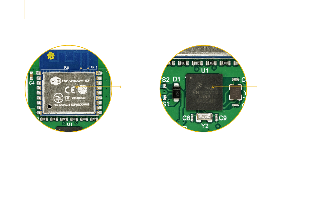
Figure 1:
ESP-WROOM-02
Finally, there is a micro USB connector, which is used to update the firmware of the Go to Cloud (G2C) click. The
firmware update is simple, error-proof, and straight-forward. More information about the update procedure can be
found in this manual.
Page 5
Figure 2:
MK64FN1
M0VDC12 MCU
Page 6

VOUT-3.3 VOUT-3.3
VCC-3.3
VCC-USB
R1
R2
1k
1k
LD1
LD2
PWR
USB
VCC-USB
CN1
1
VBUS
2
D-
3
D+
4
ID
5
GND
6
CONN_LED
STATUS_LE D
R3
1k
LD3
STAT
VCC-5V
D1
PMEG3010ER,115
R12 27
R11 27
R10
1M
TVS1 TVS2
VOUT-3.3
VCC-5V
R4
1k
LD4
CONN
VCC-5V
2.2µF
L7
C1
B11
C11
2.2µF
A11
K3
H4
E4
E3
E2
F4
E7
F7
H7
G4
F3
E6
G7
L6
F1
F2
G1
G2
H1
C5
H2
J1
J2
K1
K2
L1
L2
E1
U1
PTD15
RTC_WAKEUP_B
PTB12
PTB13
NC
NC
NC
PTE0
PTE1/LLWU_P0
PTE2/LLWU_P1
PTE3
VDD
VSS
PTE4/LLWU_P2
PTE5
PTE6
VDD
VSS
VSS
USB0_DP
USB0_DM
VOUT33
VREGIN
ADC0_DP1
ADC0_DM1
ADC1_DP1
ADC1_DM1
ADC0_DP0/ADC1_DP3
ADC0_DM0/ADC1_DM3
ADC1_DP0/ADC0_DP3
ADC1_DM0/ADC0_DM3
D2
D1
C1C2B1
PTD11
PTD13
PTD12
PTD10
PTD14
VREFH
VREFL
VSSA
VDDA
ADC1_SE16 / CMP2_IN2/A D C0_SE22
J3
F5
F6
G5
G6
32.768kHz
UART0_RTS
A10
A9
B2A2A3B3D3D4A4
B4C4A6A5B5
C3
A1
PTD1
PTD5
PTD3
PTD9
PTD8
PTD7
PTC18
PTC17
PTC19
LLWU_P13/P TD2
LLWU_P12/P TD0
LLWU_P14/P TD6
LLWU_P14/P TD4
MK64FN1M0VDC12
PTA0
PTA2
VREF_OUT/ CMP1_IN5 CMP0_IN 5/ADC1_SE1 8
ADC0_SE16/ CMP1_IN2/AD C0_SE21
L3
H3
C8
12pFC912pF
PTA1
VBAT
PTE25
DAC0_OUT/ CMP1_IN3/AD C0_SE23
DAC1_OUT/ CMP0_IN4 CMP2_IN 3/ADC1_SE2 3
XTAL32
PTE24
EXTAL32
PTE26
J5
J6
J7
L4
H5
K5
H8
K4L5K6
H6
Y2
JTAG_TDO
JTAG_TDI
JTAG_TCLK
D5B6C5
PTC15
PTC16
PTC14
PTA4/LLWU _P3
PTA5
PTA3
K7J8H9
JTAG_TMS
C6D6A7A8D7C7B7
MK64FN1M0VDC12
PTC9
PTC8
PTC7
PTC13
PTC12
PTC10
LLWU_P9/PT C5
LLWU_P10/P TC6
LLWU_P11/P TC11
LLWU_P8/PTC4
B8
LLWU_P7/PTC3
C8
PTC2
LLWU_P6/PTC1
PTC0
PTB23
PTB22
PTB21
PTB20
PTB19
PTB18
PTB17
PTB16
PTB11
PTB10
PTB9
PTB8
PTB7
PTB6
PTB3
PTB2
PTB1
LLWU_P5/PTB0
PTA29
RESET_b
PTA19
PTA18
VSS
VDD
PTA17
PTA13/LLWU _P4
PTA14
PTA16
PTA10
PTA15
PTA12
PTA11
VDD
VSS
J9
J4
E5
L8
L9
G3
K8
K9
J10
STATUS_LED
D8
ESP_RST
B9
E8
F8
F9
F10
C9
D9
E9
B10
C10
D10
VOUT-3.3
E10
D11
E11
F11
R5
G8
10k
G9
G10
ESP_EN
G11
CONN_LED
H11
J11
MCU_RST
K11
L11
K10
L10
H10
Y1
12MHz
C6
12pFC712pF
IO0
IO15
IO13
ESP_TXD
ESP_RXD
UART0_TX
UART0_RX
UART0_CTS
R15
10k
JTAG_TMS
JTAG_TCLK
JTAG_TDO
JTAG_TDI
MCU_RST
GP0 GP1
MCU_RST
UART0_CTS
GP1
GP0
IO0
12
34
56
78
C2
910
0.10µF
J1
VCC-3.3
AN
RST
CS
SCK
MISO
MOSI
+3.3V
GND
MIKROBUS DEVICE CONN
VOUT-3.3 VOUT-3.3 VOUT-3.3
VOUT-3.3
R6
10kR710kR810k
ESP_EN
IO14
IO12
IO13
IO15
R14
R13
10k
10k
VCC-3.3
IO2
PWM
INT
TX
RX
SCL
SDA
+5V
GND
C3 10µF
C4 0.10µF
1
3.3V
2
EN
3
IO14
4
IO12
5
IO13
6
IO15
7
IO2
8
IO0
GND
U2
VCC-5V
UART0_RTS
UART0_TX
UART0_RX
D2
PMEG3010ER,115
ESP-WROOM-02
R9
10k
18
18
GND
17
17
IO16
16
16
TOUT
15
ESP_RST
15
RST
14
14
IO5
13
13
GND
12
ESP_TXD
12
TXD
ESP_RXD
11
11
RXD
109
10
IO4
Figure 3: Main Schematic
Page 6
Page 7

An additional JTAG interface in the form of 2x5 pin header is used only during the production phase for the upload of
the initial firmware and it should not be used by the user, as it may lead to malfunction of the Go to Cloud (G2C) click
due to an internal firmware damage.
mikroBUS™ pins
Page 7
Page 8

Onboard indicators and LED indicators
NOTE:
The Go to Cloud (G2C) click requires both 3.3V and 5V for a proper operation.
Pins description:
∫ RST - Hardware reset - (INPUT) This pin is used to reset the MCU. This pin is internally pulled up to a HIGH logic level. Driving
this pin to a LOW logic level for 50 ms, a reset function will be performed. After each reset cycle, the complete boot sequence
of the Go to Cloud (G2C) click is repeated.
Page 8
Page 9

∫ CTS - Clear to send
is ready to receive data sent from Go to Cloud (G2C) click.
∫ RTS - Request to send
is ready to accept incoming data from the host MCU. There is also a secondary function of this pin: if set to a HIGH
logic level during the boot-up sequence, the five-second bootloader timeout will be completely skipped, allowing for
a faster start of the Go to Cloud (G2C) click. More information about the secondary function of this pin is provided in the
Boot-up section of this manual.
∫ GP0, GP1 - General purpose pins
is ready to receive data sent from Go to Cloud (G2C) click.
[1]
The current version of the firmware (ver.F091) does not have these options implemented yet, but they are
planned to be added in future updates.
[1]
- (INPUT) A LOW logic level on this pin means that HOST MCU
[1]
- (OUTPUT) A LOW logic level on this pin means that the Go to Cloud (G2C) click
[1]
- (INPUT) A LOW logic level on this pin means that HOST MCU
UART interface – configuration:
∫ Baud rate: 57600
∫ Data bits: 8
∫ Parity: NO
∫ Stop bit: 1
Page 9
Page 10

The complete control of the Go to Cloud (G2C) click is done over the UART interface, by using AT commands. The list
of the available AT commands, along with the explanation and example for each of them can be found in the
AT Command Manual.
The Go to Cloud (G2C) click firmware accepts AT commands, which can be sent over the UART interface pins of
the mikroBUS™, either from a terminal application on a personal computer (with the addition of the USB-to-UART
adapter) or from the host MCU. When transmitting the AT command string, a timing interval between consecutive
characters should not exceed 5 seconds. The timing interval greater than 5 seconds is considered as the EOL for any
AT command (end-of-line), and the received command will be parsed as such.
More information about all the available AT commands with the detailed explanation can be found in the AT Commands Manual.
UART interface – configuration:
After the power-on, the Go to Cloud (G2C) click will start in the bootloader mode, which will be terminated after 5
seconds. During these 5 seconds, the MK64F MCU onboard the Go to Cloud (G2C) click will be visible to the USB
HID Bootloader application, allowing its firmware to be updated. When the connection with the USB HID Bootloader
application is established, it will take over the control of the Go to Cloud (G2C) click and will keep it in the bootloader
Page 10
Page 11

mode. If there is no response from the USB HID Bootloader application while the Go to Cloud (G2C) click is in the
bootloader mode, the normal operation of the Go to Cloud (G2C) click will be resumed and the MK64F MCU will not be
visible for the USB HID Bootloader application anymore.
After a connection with the USB Bootloader application is established, the STAT LED will be turned on and it will stay
that way as long as the bootloader mode is active. Leaving the bootloader mode will be indicated by the CONN LED,
which will blink once, while the STAT LED will be turned off.
The bootloader mode will be automatically initiated after each power-on event, leading to a five-second startup
delay. To skip the bootloader mode completely and boot-up directly into the normal mode, the CTS pin can be set to
a HIGH logic level after the restart, for at least 100ms. This prevents the five-second delay during the power on if the
firmware update was not intended, shortening the boot-up time before the G2C click is ready to be used.
During the boot-up sequence, the default configuration values will be restored from the internal non-volatile memory.
More details about storing and restoring the default configuration parameters can be found in the AT Commands
Manual.
The end of the boot-up sequence will be indicated by a single blink of both the STAT and CONN LEDs, simultaneously.
NOTE:
After leaving the bootloader, a delay of at least 3 seconds has to be made, allowing the connector module to reboot properly.
Page 11
Page 12

Firmware update
The G2C click is shipped with the latest version of
firmware. However, the firmware will be continuously
improved in the future. Therefore, the Go to Cloud (G2C )
click has a firmware update option, in a form of a micro
USB connector (CN1) and an implementation of the HID
bootloader within the firmware itself.
To properly update the firmware, please use the provided
micro USB connector (CN1) with the HID bootloader
application and a proper firmware file. The JTAG 2x5-pin
header (J1) is not to be used for uploading the update
since it can destroy the base firmware and render the
G2C click inoperable. It is used only for the initial firmware
update during the production. The Go to Cloud (G2C )click
is shipped with this header unpopulated.
The firmware update can be done by using the USB HID
Bootloader application. After a USB cable is connected to
the micro USB connector on the Go to Cloud (G2C )click,
the application will detect the onboard MK64F MCU, as
displayed on the picture below:
Figure 4: USB HID Bootloader connected to the Go to
Cloudd (G2C) click
Page 12
Page 13

Note that there is a five seconds timeout interval during which the Go to Cloud (G2C )click operates in a firmware update
mode as explained in the Boot-up sequence section of this manual. After this, the Go to Cloud (G2C )click is restarted and
will continue running in a normal mode, completely skipping the bootloader, and will be undetectable for the HID bootloader
application. If this happens, it is necessary to disconnect the USB cable and connect it again, initiating another five seconds
interval.
After the MCU of the Go to Cloud (G2C )click is detected as on the picture above, an appropriate HEX file with a proper
firmware version should be selected by clicking on the Browse for HEX button. This will open a file selection window, where
you can browse for the updated firmware file with the .hex extension. Once selected, the programming process can be
started by clicking the Begin uploading button. The programming process should take up to 60 seconds. If it takes longer, or
the process is interrupted during the update, it should be repeated from the beginning.
Page 13
Page 14

DISCLAIMER
All the products owned by MikroElektronika are protected by copyright law and international copyright treaty. Therefore, this manual is to be treated as any other copyright material.
No part of this manual, including product and software described herein, may be reproduced, stored in a retrieval system, translated or transmitted in any form or by any means,
without the prior written permission of MikroElektronika. The manual PDF edition can be printed for private or local use, but not for distribution. Any modification of this manual is
prohibited. MikroElektronika provides this manual ‘as is’ without warranty of any kind, either expressed or implied, including, but not limited to, the implied warranties or conditions of
merchantability or fitness for a particular purpose. MikroElektronika shall assume no responsibility or liability for any errors, omissions and inaccuracies that may appear in this manual.
In no event shall MikroElektronika, its directors, officers, employees or distributors be liable for any indirect, specific, incidental or consequential damages (including damages for loss of
business profits and business information, business interruption or any other pecuniary loss) arising out of the use of this manual or product, even if MikroElektronika has been advised
of the possibility of such damages. MikroElektronika reserves the right to change information contained in this manual at any time without prior notice, if necessary.
HIGH RISK ACTIVITIES
The products of MikroElektronika are not fault – tolerant nor designed, manufactured or intended for use or resale as on – line control equipment in hazardous environments
requiring fail – safe performance, such as in the operation of nuclear facilities, aircraft navigation or communication systems, air traffic control, direct life support machines
or weapons systems in which the failure of Software could lead directly to death, personal injury or severe physical or environmental damage (‘High Risk Activities’).
MikroElektronika and its suppliers specifically disclaim any expressed or implied warranty of fitness for High Risk Activities.
TRADEMARKS
The MikroElektronika name and logo, mikroC, mikroBasic, mikroPascal, Visual TFT, Visual GLCD, mikroProg, Ready, MINI, mikroBUS™, EasyPIC, EasyAVR, Easy8051, Click boards™ and
mikromedia are trademarks of MikroElektronika. All other trademarks mentioned herein are property of their respective companies.All other product and corporate names appearing in
this manual may or may not be registered trademarks or copyrights of their respective companies, and are only used for identification or explanation and to the owners’ benefit, with
no intent to infringe.
The FTDI Chip® and Windows® logos and product names are trademarks of FTDI Chip and Microsoft® in the U.S.A. and other countries.
Copyright © 2019 MikroElektronika. All Rights Reserved.
Page 14
Page 15

If you want to learn more about our products, please visit our
website at www.mikroe.com
If you are experiencing some problems with any of our
products or just need additional information, please place
your ticket at www.mikroe.com/support
If you have any questions, comments or business proposals,
do not hesitate to contact us at office@mikroe.com
Designed by
MikroElektroni
ka Ltd.
 Loading...