

C O D E G R I P U S E R M A N U A L
USER MANUAL
P A G E 1

Thank you for choosing Mikroe!
We present you the ultimate debugger and programmer over USB/WiFi solution for embedded development.
Elegant on the surface, yet extremely powerful on the inside, we have designed it to inspire outstanding achievements.
And now, it’s all yours.
Enjoy premium.

Table of contents
Introduction 5
1. Installing CODEGRIP Suite 6
2. CODEGRIP 8
2.1 USB connectivity 9
2.2 WiFi connectivity 9
2.3 Target connector 10
2.4 CODEGRIP adapters 11
2.5 LED indicators 13
3. CODEGRIP Link structure 14
2.1 Link types 14
2.2 Link states 14
4. CODEGRIP Suite overview 16
4.1 Menu section 17
4.2 Menu item section 17
4.3 Shortcuts bar 17
4.4 Status bar section 18
5. CODEGRIP Suite explained 19
5.1 Target MCU 19
5.2 CODEGRIP 28
5.3 POWER 38
5.4 OPTIONS 38
5.5 HELP 40
Troubleshooting 42

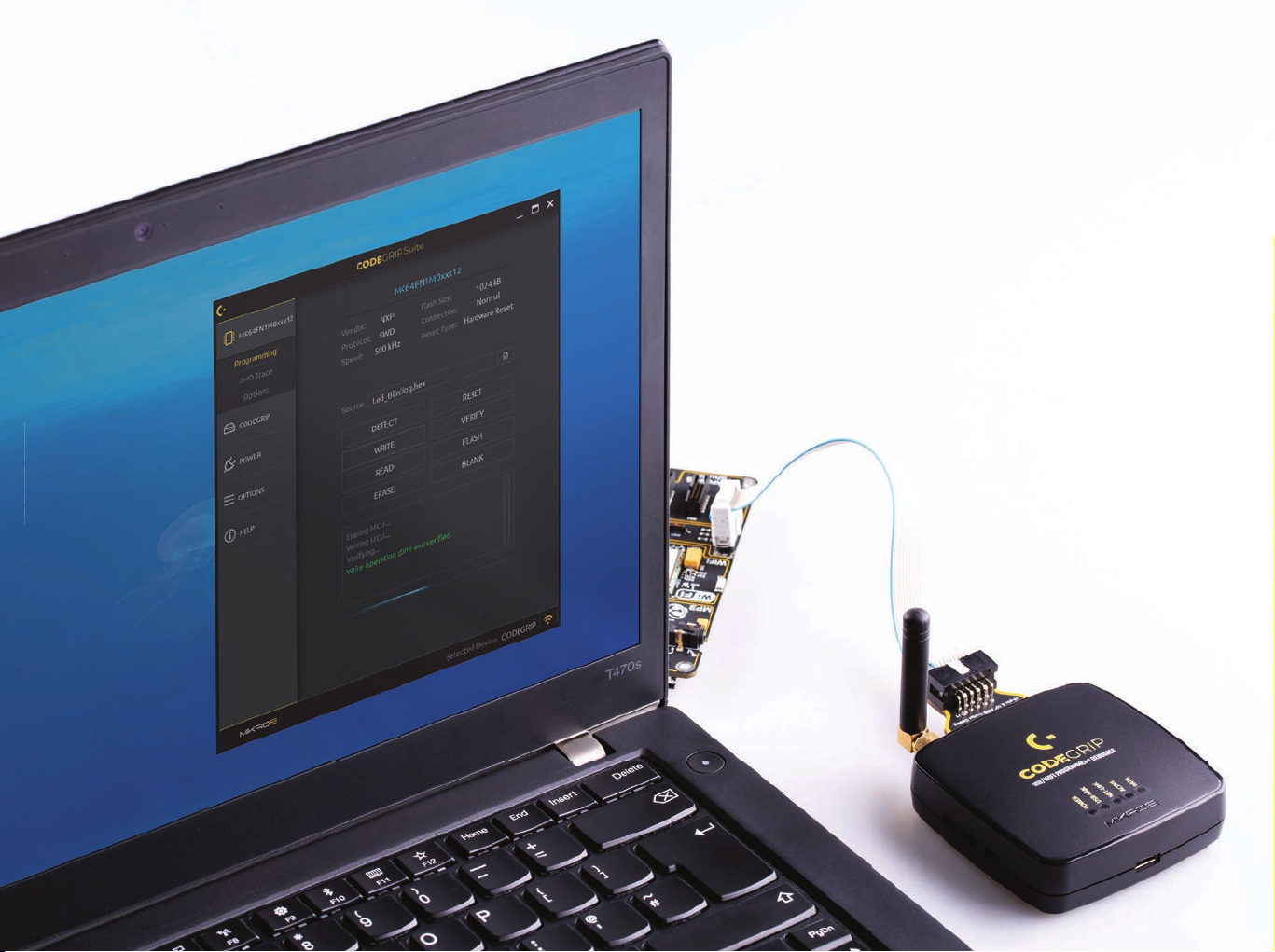
CODEGRIP is a unified solution, designed to perform
based microcontrollers becomes seamless and effortless,
programming and debugging tasks on a range of different
microcontroller devices (MCUs) based on the ARM
®
Cortex®-M
architecture. By bridging differences between various MCUs,
it allows a huge number of MCUs from several different
MCU vendors to be programmed and debugged. Although
the number of supported MCUs is absolutely huge, more
MCUs might be added in the future, along with some new
functionalities.
Thanks to some advanced and unique features such as
wireless connectivity and USB-C connector, the task of
programming of a huge number of various ARM
®
Cortex®-M
providing users with both the mobility and the complete
control over the microcontroller programming and debugging
process. The USB-C connector offers improved performance
and reliability, compared to traditionally used USB Type A/B
connectors. Wireless connectivity redefines the way the
development board can be used.
The graphical user interface (GUI) of the CODEGRIP Suite is
clear, intuitive, and easy to learn, offering a very pleasant user
experience. The embedded HELP system provides detailed
guidelines for every aspect of the CODEGRIP Suite.
C O D E
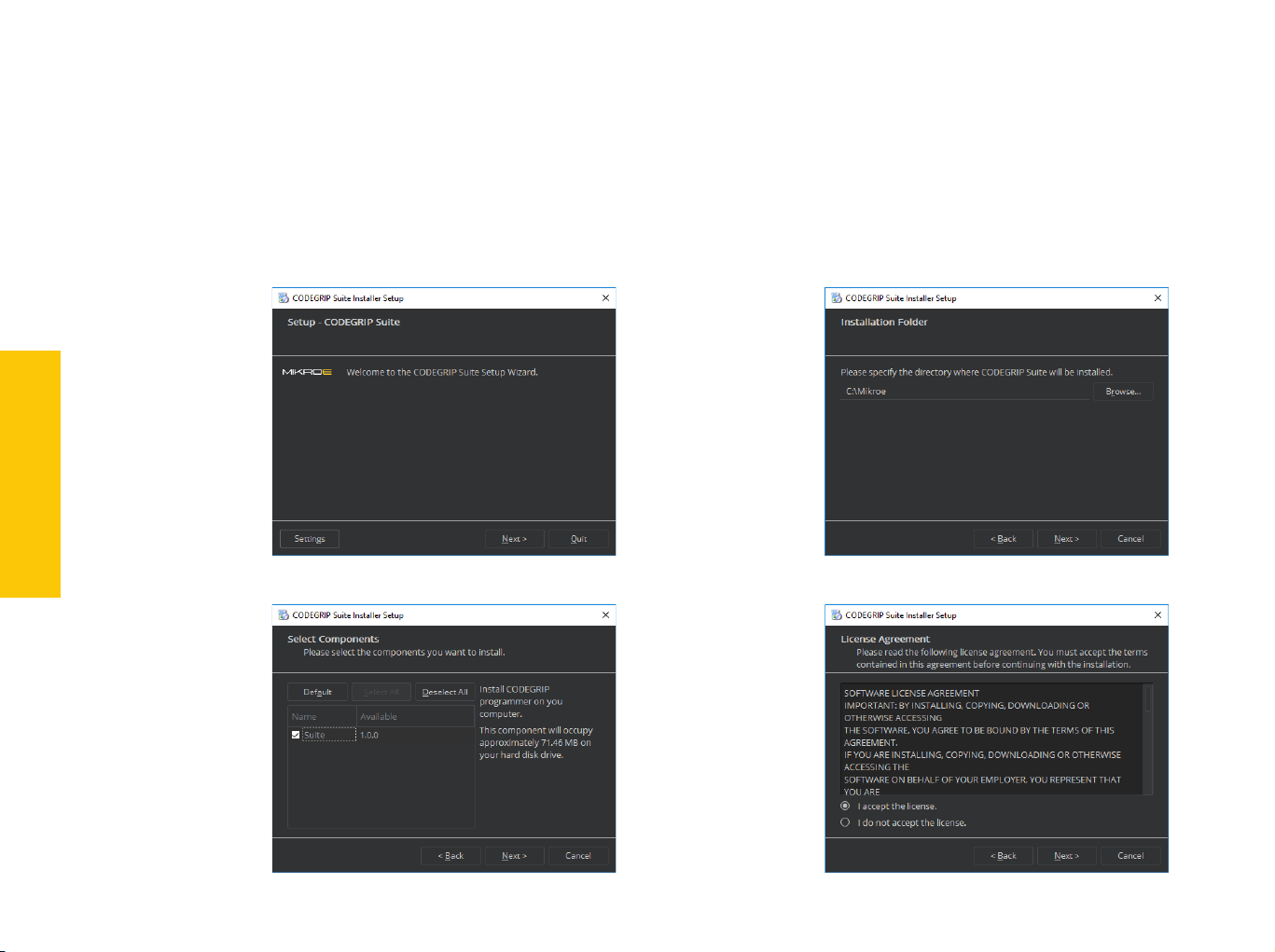
1. Installing CODEGRIP Suite
The installation process is easy and straightforward.
Download CODEGRIP Suite software application from the link www.mikroe.com/setup/codegrip and follow the steps
below.
INSTALLATION
P A G E 6
1.
Start the
installation
3.
Select the
components
to install
2.
Select the
destination
folder
4.
License
agreement
G R I P U S E R M A N U A L
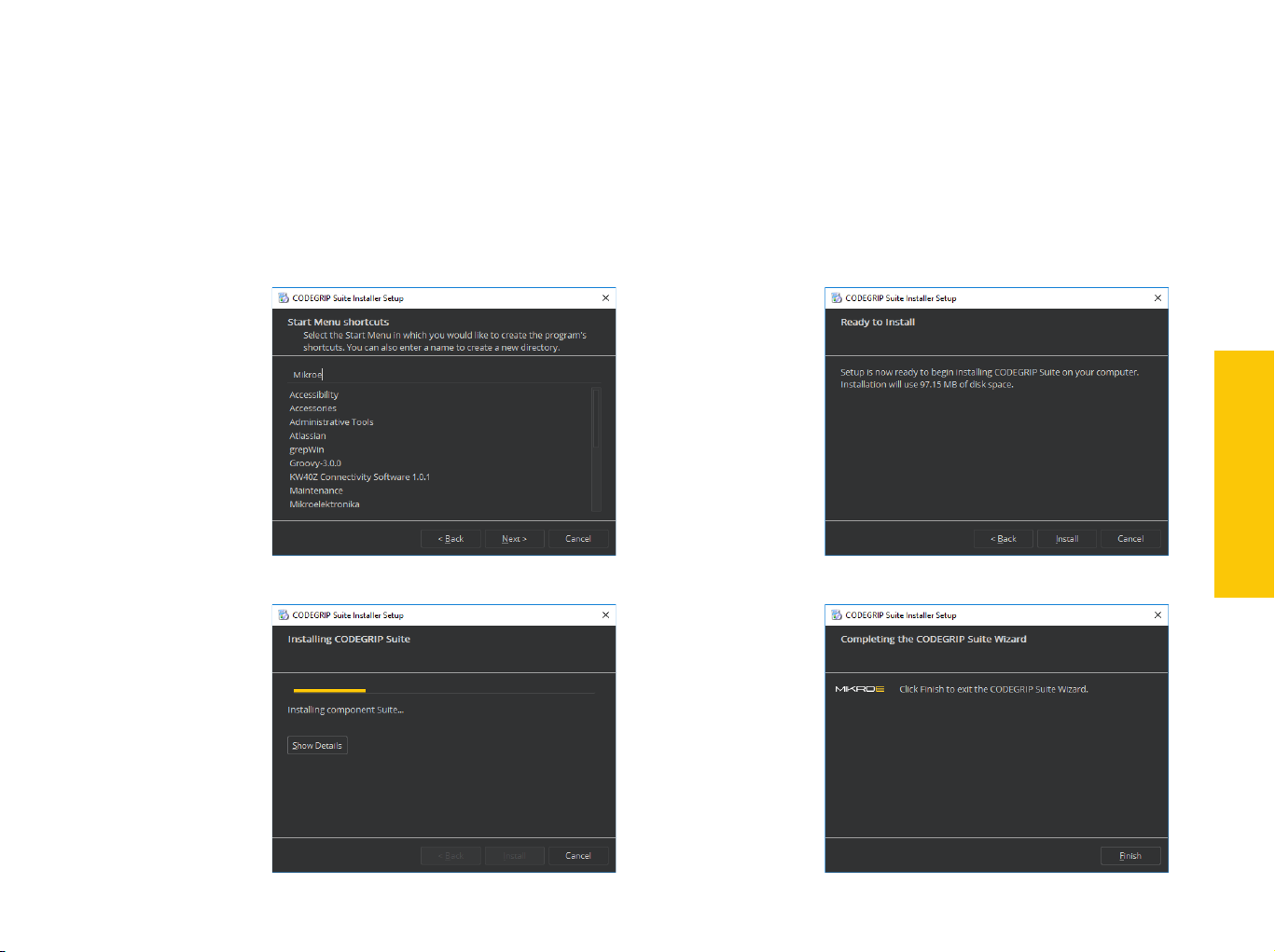
5.
6.
Select the
start menu
shortcuts
7.
Installation
progress
Start the
installation
process
8.
Finish the
installation
process
INSTALLATION
P A G E 7
C O D E G R I P U S E R M A N U A L
C O D E
C O D E
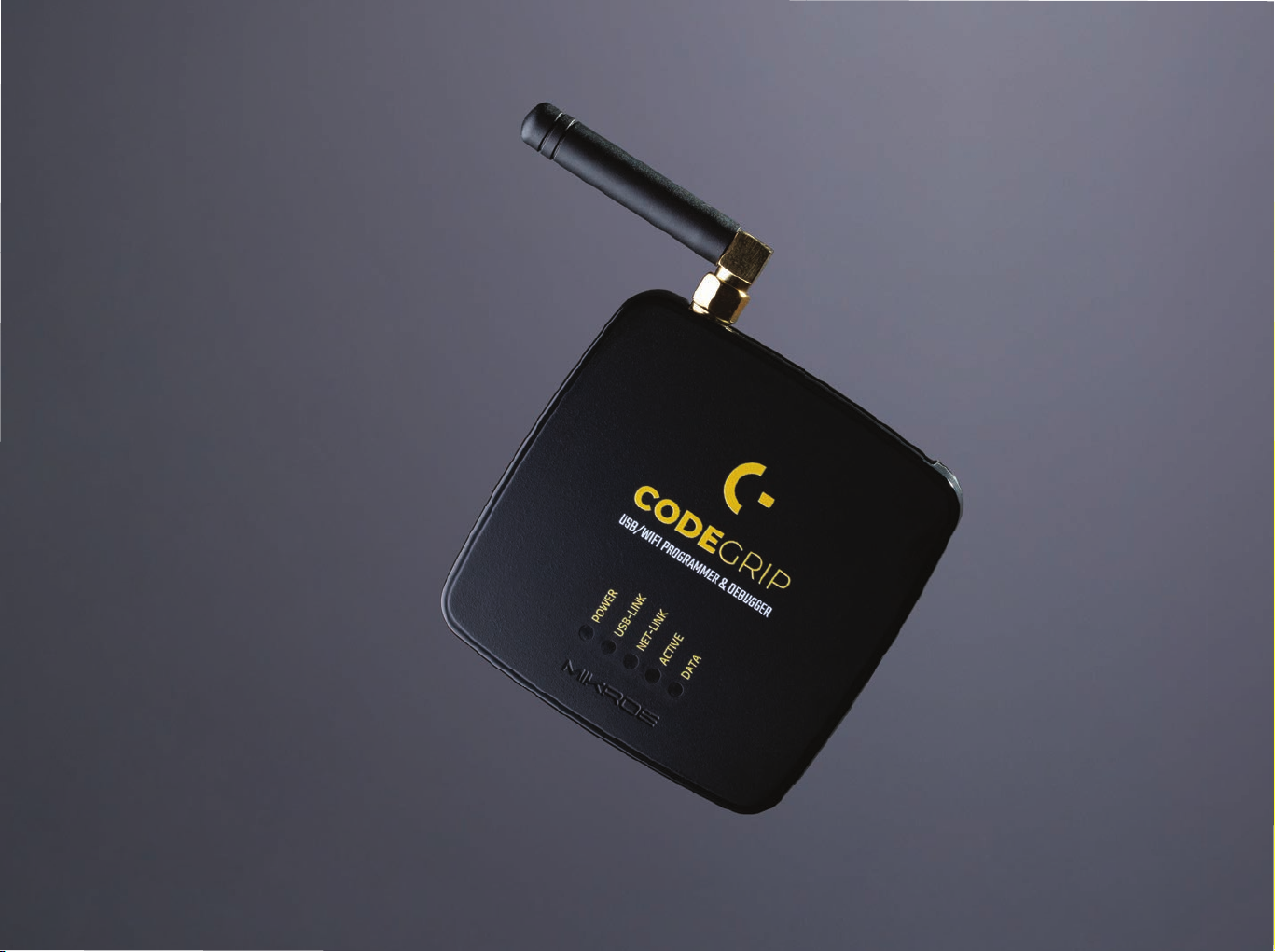
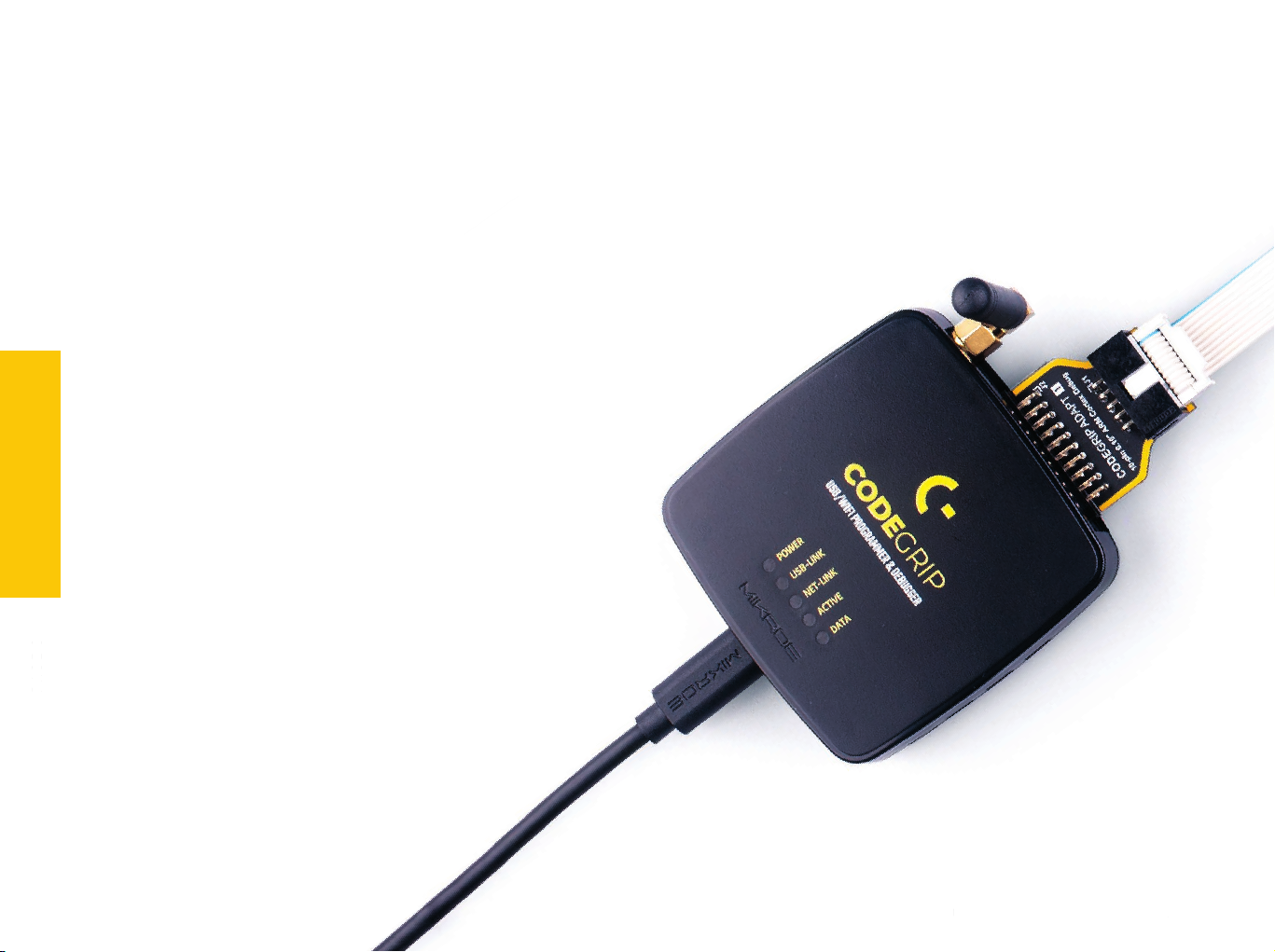
2. CODEGRIP
The CODEGRIP device offers a set of unique and innovative
functionalities, some of which have never been used before
on a similar device. These functionalities include wireless
programming and debugging, power monitoring, advanced
debugging options with the SWO support, and more.
The CODEGRIP device comes in two different types: as a
CODEGRIP
P A G E 8
P A G E 8
stand-alone device and an integrated on-board module. This
manual will be focused on the stand-alone CODEGRIP device.
In order to better understand how this device is operated, this
chapter will give you a brief overview of its basic hardware
functions.
G R I P U S E R M A N U A L
2.1 USB connectivity
The USB-C connector is the latest upgrade of the conventional USB A/B
type connectors, typically found on most personal computers today. The
USB-C connector has many advantages over the USB type A/B connector
such as the completely symmetrical design which reduces the possibility
of the connector misalignment and the damage it might cause, higher
current capability, and more. However, if there is not appropriate USB-C
connector on the host PC, a USB-C cable adapter can be used.
2.2 WiFi connectivity
The CODEGRIP device can be linked with the CODEGRIP Suite over the WiFi
network, allowing it to program and debug the target MCU wirelessly. This
is a revolutionary new feature, which allows some unique usage scenarios,
currently not available on any other programming/debugging solution in
the world. The WiFi connectivity option offers a complete autonomy of
the development system. Running a toxic gas sensor application while
debugging the firmware in real time, programming it with a new firmware
during exposure, having sensor responses collected and logged remotely
from several different base points, debugging drone firmware while it is in
mid-air… This is just a simple example of what CODEGRIP can offer.
The WiFi module on the CODEGRIP device has an integrated chip antenna,
which allows good WiFi reception. However, if a stronger WiFi signal is
required, the CODEGRIP device offers an SMA connector for an external
WiFi antenna.
The WiFi link can be protected by a password, or by the MAC address
filtering option.
can be bought from the official Mikroe online store www.mikroe.com
CODEGRIP
P A G E 9
P A G E 9
N O T ETo use the WiFi functionality, a separate registration code is required. It
C O D E G R I P U S E R M A N U A L
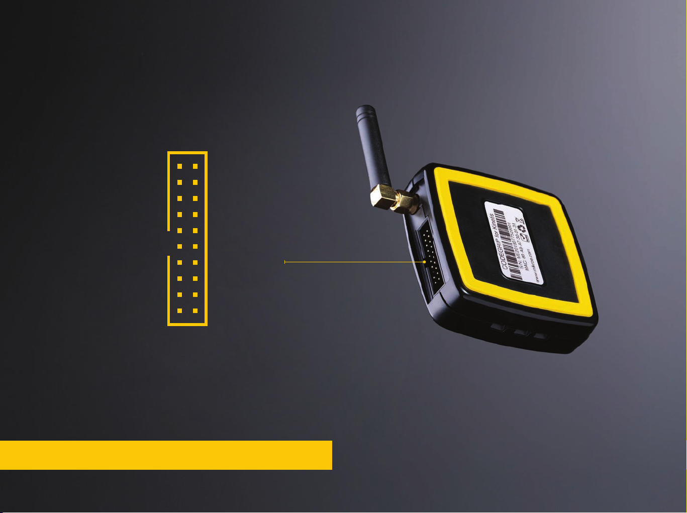
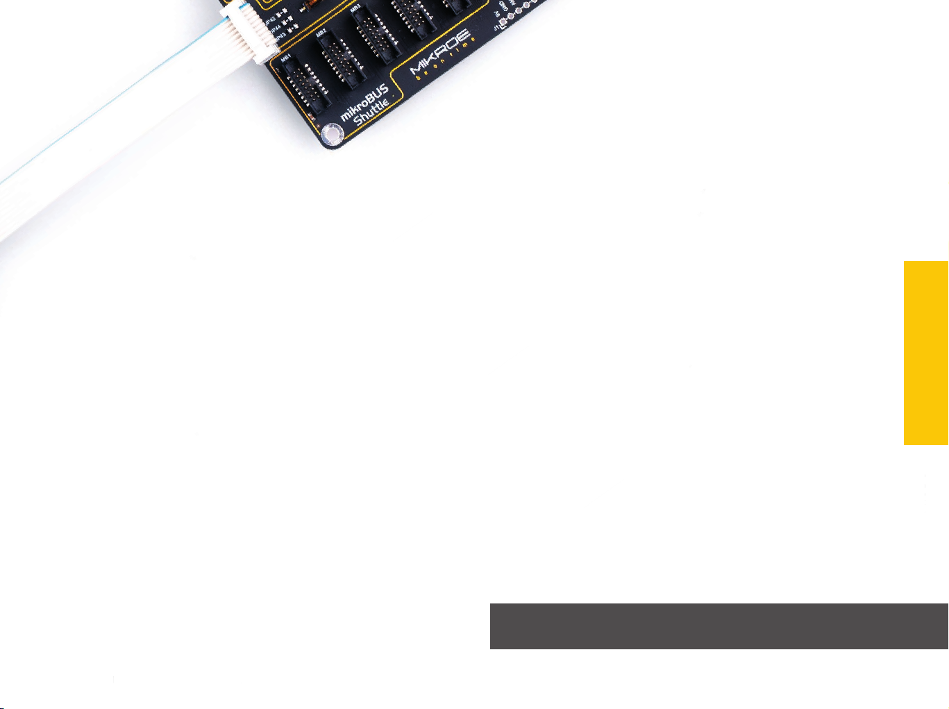
2.3 Target connector
The CODEGRIP device can be used with any hardware, equipped with the
standard JTAG/SWD programming header. Packed in a sturdy casing with
rubber feet, it can be used independently, bringing all the powerful features
to a third-party hardware.
SWDIO/TMSVCC-TGT
GND
GND
PROG MUX/GND
GND
GND
GND
GND
The CODEGRIP device is equipped with the target MCU connector, which
contains JTAG/SWD and power supply pins. This connector is used to
interface the CODEGRIP device with the target MCU, allowing it to perform
programming and debugging operations, to provide the power supply for
the target MCU, and to be used as the power input when the CODEGRIP
device is powered from the connected development board.
N O T E When the connected host board provides power to the CODEGRIP
device, CODEGRIP input voltage must be in range 2.5V to 10V.
SWDCLK/TCK
SWO/TDO
TDI
TGT-RESET
TRACECLK
TRACEDATA-0
TRACEDATA-1
TRACEDATA-2
TRACEDATA-3GND
On the bottom of the CODEGRIP device there is the sticker which contains
additional information.
∫ Supported MCU family/architecture
∫ Unique serial number
∫ Unique WiFi MAC address
CODEGRIP firmware
The CODEGRIP device is based on the powerful 32-bit MCU, which utilizes a
complex firmware to provide all the required functionalities. The firmware
will be continuously improved so that additional optimizations, functions,
and support for new MCU families might be added in the future. Therefore,
the complete CODEGRIP programming environment is designed so that
the firmware upgrade process is effortless and easy.
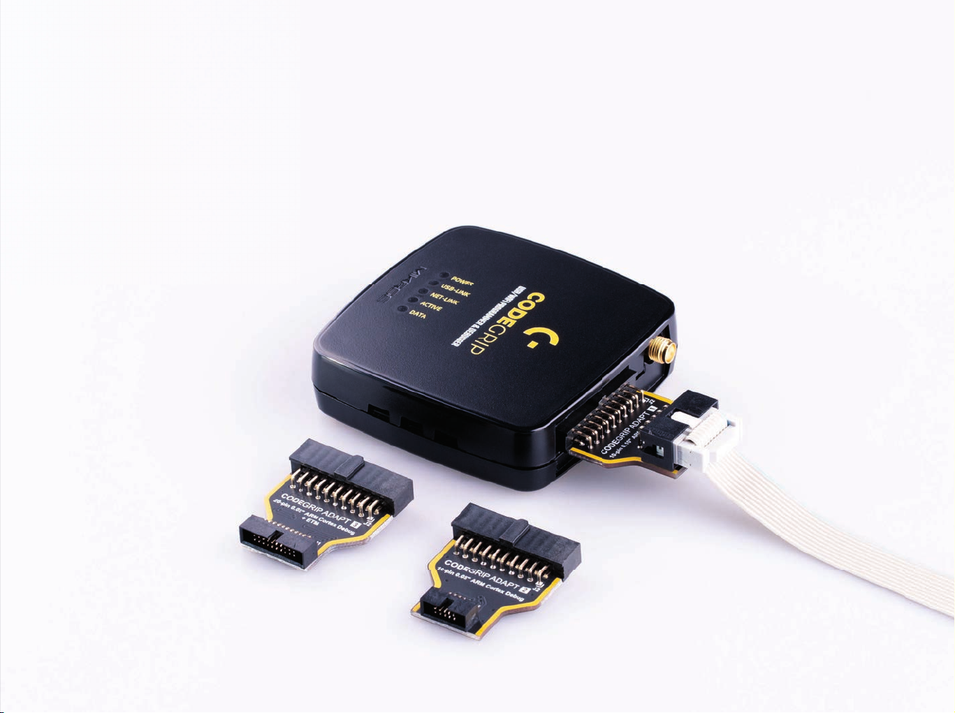
2.4 CODEGRIP adapters
JTAG/SWD programming/debugging headers may vary across different
hardware applications. To ensure compatibility with various header
configurations there is a set of different adapters available as an additional
purchase option.
CODEGRIP
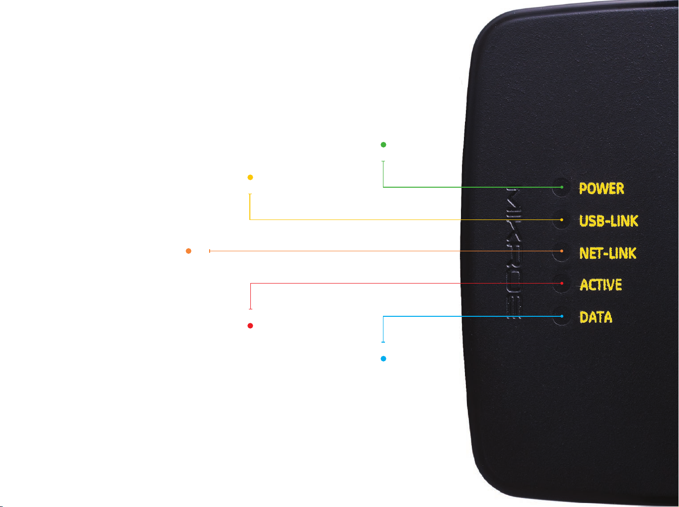
2.5 LED indicators
There are five LED indicators on the CODEGRIP device, used to indicate
different states of the device, providing visual feedback to the user.
Indicates the
USB-LINK
Indicates that the
connection has been
established via USB
NET-LINK
Indicates that the
connection has been
established via WiFi
ACTIVE
Blinking LED indicates that the
CODEGRIP device is
in the bootloader mode
Steady ON LED state indicates
the normal operation of the
CODEGRIP device
Indicates the data
transfer between the
target MCU and the
CODEGRIP device
POWER
presence of
the power
supply
DATA

C O D E
3. CODEGRIP link structure
CODEGRIP Suite can detect multiple CODEGRIP devices. In addition, a
single CODEGRIP device can be operated by multiple software applications.
To avoid any ambiguity, CODEGRIP utilizes the concept of links.
CODEGRIP Suite uses a link to the specific CODEGRIP device, in order to send
commands and receive responses. The link can be created, opened, and
destroyed by the user, employing some specific functions of CODEGRIP Suite.
Based on the link and its state, CODEGRIP Suite can always unambiguously
know which CODEGRIP device to use, and if the specific CODEGRIP device
is currently available. A single CODEGRIP device can have links to multiple
CODEGRIP Suite applications, while CODEGRIP Suite can have a link to only
a single CODEGRIP device at time. Still, it can easily switch the link to any
LINK STRUCTURE
CODEGRIP device detected during the scanning process.
3.1 Link types
Depending on what type of interface is used to establish the link, there are
P A G E 14
N O T E USB link is the primary link and it has the highest priority. Some
two types of links available: the USB link, and the WiFi link.
operations, such as the firmware update, are exclusively used with
the USB link. When the USB link is active, all the WiFi links to that
specific CODEGRIP device will be forced to a closed state.
3.2 Link states
Each link has several different states recognized by the CODEGRIP Suite.
The link is Closed: the CODEGRIP device is not available over the
communication interface (USB or WiFi). Either it is disconnected,
nonresponsive, turned OFF, or otherwise unavailable.
The link is Available: the CODEGRIP device is available over the
communication interface (USB or WiFi). Communication packets can
reach the CODEGRIP device, and it is able to send back the response.
The link is Blocked: this state indicates that the link was blocked because
the specific CODEGRIP device is busy servicing another link.
When CODEGRIP Suite actively uses the link for issuing commands to a
linked CODEGRIP device, other applications linked to the same CODEGRIP
device will have their links in a blocked state. As soon as the task is
complete, those links will revert to the available state.
The indicator showing the current state is visible at the status bar at
the bottom of the Suite. More detailed description about the Shortcut bar
commands find in the Chapter 4.
G R I P U S E R M A N U A L


C O D E
4. CODEGRIP Suite overview
The graphical user interface (GUI) of CODEGRIP Suite is clear, intuitive, and
easy to use, which ensures a fluid workflow. The main window is divided into
several sections, which are used to display and organize all information,
tools, and options in a consistent and comprehensible manner.
Besides the very informative Help system, CODEGRIP Suite also offers a
short description for the most of its functionalities in a form of a hovering
tooltip. It is enough to keep the mouse hovering above the specific
graphical element for a while, and a small tooltip will pop up, providing
some basic info.
The following chapter explains the GUI layout and its main elements. GUI of
the CODEGRIP Suite can be divided into several sections:
CODEGRIP SUITE
1. Menu section
2. Menu Item section
P A G E 16
3. Shortcut bar
4. Status bar
1 42 3
G R I P U S E R M A N U A L

4.1 Menu section 4.3 Shortcuts bar
As already mentioned, all Menu buttons are located in the Menu section (1)
of the CODEGRIP Suite GUI. By clicking a Menu button, one or more Menu
items are unfolded. Menu items are grouped by the type of the function
they are related to. For example, clicking the CODEGRIP Menu button will
unfold Scanning, Configuration, and License Menu items. All these Menu
items are related to configuring and working with CODEGRIP devices, and
therefore they are grouped under the CODEGRIP Menu button.
4.2 Menu item section
When a Menu item is clicked, the Menu item section (2) will display all
the GUI elements available for that specific Menu item. For example,
if the Programming Menu item is clicked, the Menu item section of the
GUI will show some basic information about the target and controls for
MCU programming tasks. Each Menu item will display its own set of GUI
elements in the Menu item section of the GUI interface when clicked.
The Shortcuts bar (3) is another persistent section of the CODEGRIP
Suite GUI, containing controls for the most commonly used commands. It
appears on the top of the Menu item section, just below the title bar. The
only Menu item that does not include the Shortcuts bar is the Programming
Menu item since all the shortcut commands are already included there.
Icons on the Shortcuts bar are used to speed up the workflow, providing
easy access to a set of commands from within any Menu item of CODEGRIP
Suite. This is basically a set of commands otherwise found under the
Programming Menu item, including the most commonly accessed
CODEGRIP commands: WRITE command, DETECT command and VERIFY
command, along with the interface used to select .hex or .bin file.
More detailed description about the Shortcut bar commands find in the
Chapter 5.
CODEGRIP SUITE
P A G E 17
C O D E G R I P U S E R M A N U A L

C O D E
4.4 Status bar section
The Status bar (4) is located at the very bottom of the GUI and it is used to
provide persistent visual feedback about the CODEGRIP link status. A set of
indicators along with a related text field allowing the user to always know
the status of the CODEGRIP link.
Selected Device: This text field is used to either display the name of the
CODEGRIP device which is currently linked to CODEGRIP Suite. If the link
has been destroyed by the user, or has not been created yet, the message
“None” will be displayed instead. Hovering the mouse above the message
CODEGRIP SUITE
P A G E 18
will highlight it (yellow), indicating that it is clickable.
Two actions will be performed when clicking the message in the Selected
Device field:
∫ If the message “None” is displayed, the Scanning Menu item will be
activated if clicked.
∫ If there is a CODEGRIP device name displayed in this field, the
Configuration Menu item will be activated if clicked.
Link status indicator: provides visual feedback about the status of the link.
When working with multiple devices, it is sometimes useful to have visual
indication of the device which is currently linked with the CODEGRIP Suite.
When the Link status indicator is clicked, the linked device will respond by
blinking its ACTIVE LED.
Color-coding scheme examples:
Update availability indicator: As a part of the startup procedure,
CODEGRIP Suite checks if there is a software update available. If a new
update is available, it will display a notification icon on the status bar,
indicating that there is a new version of CODEGRIP Suite available for
download. This notification icon can be suppressed by configuring the
options found in the OPTIONS/General Menu item.
G R I P U S E R M A N U A L

5. CODEGRIP Suite explained
As already mentioned, each Menu button contains one or
more related Menu items, and each Menu item contains its
own set of tools and options, displayed in a form of various
GUI elements on the Menu item section. This chapter provides
detailed information on these tools and options.
5.1 Target MCU
Menu items used to interact with the target MCU (the selected MCU upon
which the CODEGRIP device performs various programming/debugging
tasks) are folded under this Menu button. The Menu button is labeled
dynamically, according to the selected target MCU. This allows the user to
always be aware of which MCU is set as the target MCU, regardless of the
currently selected Menu item. There are three Menu items available, folded
under this Menu button: Programming, SWO Trace and Options.
C O D E G R I P U S E R M A N U A L
PROGRAMMING
P A G E 19

C O D E
5.1.1 Programming
PROGRAMMING
the selected MCU vendor, the programming protocol, connection speed,
the flash size of the target MCU, the connection type, and the reset type.
Below is the interface used to select and display the program file .bin or
.hex file, ready to be uploaded to the target MCU or examined by using a set
of options, accessible by clicking the FLASH button.
There is also the programming interface, composed of a set of buttons,
used to perform various programming commands. These commands will
be explained in this chapter.
On the bottom of the Menu item section, there is a panel which displays
different status messages during the programming process, along with the
progress bar. Each command returns a message response and displays it
on this panel. In general, messages displayed with green letters indicate a
successful execution, while messages displayed with red letters indicate
an error during the execution of specific command.
P A G E 20
Troubleshooting steps required for resolving of issues reported during the
execution of the programming commands are listed at the end of this
manual, in the Troubleshooting section.
The Programming Menu item displays all the commands, parameters, and
other information, related to the programming process itself.
When the Programming Menu item is clicked, a quick summary of the
selected programming options is displayed on the top of the Menu item
section, grouped under a label which displays the name of the target MCU:
G R I P U S E R M A N U A L

SOURCE
The name of the currently loaded .hex or .bin file is displayed in this field.
This file contains the program data that will be uploaded to the target MCU.
Next to this textbox is a browse button, which opens a file selection dialog
window, used to browse the .hex or .bin file.
VERIFY button
VERIFY button is used to compare the content of the loaded source file
with the content of the target MCU memory.
The source file selection dialog window can also be opened by using the
keyboard shortcut [Ctrl+O]. Finally, the drag & drop functionality from the
host OS is also supported by CODEGRIP Suite.
The right-click menu is supported. There are Copy File Name, Copy Full
Path, and Remove File options.
The content of the loaded source file can be viewed using the FLASH button.
DETECT button
DETECT button is used to verify the MCU.
RESET button
RESET button will perform a reset of the target MCU.
WRITE button
WRITE button performs programming of the target MCU. It will upload
the program from the loaded source file to the target MCU, using the
programming protocol, speed and other parameters found in the TARGET/
Options Menu item. Before memory is written, the target MCU flash will be
erased.
ERASE button
The ERASE button is used to erase the entire flash memory content of the
target MCU.
BLANK button
The BLANK button is used to verify the status of the target MCU memory.
If memory is blank (i.e. memory was erased by the ERASE command), an
appropriate message will be displayed.
PROGRAMMING
P A G E 21
N O T EThe functionality of these commands can be further adjusted by
configuring the Verification Type settings, found in the OPTIONS/
General Menu item.
C O D E G R I P U S E R M A N U A L

C O D E
READ button
Find
READ button performs a reading of the target MCU flash memory content.
The content of the memory is then available for the FLASH button related
functions.
FLASH button
FLASH button opens the Memory View window which displays the table
view of the memory content. There are two tabs in this window: Memory
View and Loaded Source. The Memory View tab displays the target MCU
memory content. The Loaded Source tab displays the content of the
loaded .bin or .hex source file. Note that if there is no source file loaded,
the Loaded Source tab will reflect this condition by changing its label to
“File is not loaded”.
Cell size can be configured to show 8-bit, 16-bit or 32-bit data per cell, by
using the three buttons on the bottom of the Memory View window, labeled
X1, X2, and X4.
PROGRAMMING
The last column displays the data converted to ASCII characters.
Data listed on both the Memory View and Loaded Source tabs can be
exported as a .bin or .hex file. Clicking the SAVE button located on the
P A G E 22
bottom right corner of the Memory View window will open a new file dialog,
allowing to enter the filename and the path for the exported file.
This function is used to search for an occurrence of the value specified in
the textbox.
Goto Address
By using the text box, you will jump to your specify memory location.
If the specified value is not a valid address, the corresponding action will
be disabled.
The length of the search value should match the selected cell size. If data
length for the search pattern is not valid, the Find button will be disabled.
G R I P U S E R M A N U A L
N O T E

5.1.2 SWO Trace
on the Cortex®-M3, M4, and M7 core. It is perfectly suited to output debug
and runtime information and monitor the performance of the application
in real time, without using processing resources, and without the need for
complex coding routines.
To simplify working with the SWO trace port, Mikroe has provided the
SWO library with ready-made functions, which can drastically speed up
the software development. The library is available for download from
the Libstock at libstock.mikroe.com
Monitoring Interval
The monitoring interval can be specified in this text fi eld. The collected
SWO messages will be displayed on the lower part of the Menu item
section after the specified monitoring interval expires. If the internal buffer
becomes full, an overflow error message will be displayed. In that case, the
monitoring interval should be decreased.
Baud Rate
SWO
SWO (Serial Wire Output) trace is used to display various SWO-related
messages in the Menu item section of the CODEGRIP Suite. The ARM SWO
trace port uses a single pin to stream out data packets over 32 different
ports, using the specified clock rate. The SWO is a part of the ARM
CoreSight Debug module which is incorporated in most of the MCUs based
C O D E G R I P U S E R M A N U A L
The baud rate of the SWO Trace clock can be specified i n t his text fi eld.
It needs to be matched with the baud rate used in the SWO software,
running on the target MCU. Otherwise, SWO data might get corrupted and
the messages might not be displayed at all. To change the baud rate, the
Monitoring Status needs to be paused.
Monitoring Status
Options: Paused, Active
®
When Paused, the SWO trace messages will not be collected and displayed on
CODEGRIP Suite GUI. When set to Active, the SWO monitoring will be resumed.
P A G E 23

C O D E
SWO
Set Filters
This button opens a new window, which contains five checkboxes, used to
manage the incoming SWO messages. There are three message categories,
depending on the SWO port they are sent through: Info, Warning, and Error
messages. When the specific checkbox is ticked, messages corresponding
to that category will be displayed.
The categories are color-coded. Info messages are displayed with the light
blue letters, Warning messages are displayed using the yellow color, while
the Error messages are displayed in red.
The Default category is used to manage messages sent over any other
SWO port that is not either Info, Warning, or Error port. These messages
are displayed in grey color.
The last checkbox labeled as Port is used to show or hide the port number
and the category of the specific incoming message. If multiple messages
are received over the same port, the port number and the category
message will be displayed only before the first message, respecting the
previously explained color coding scheme.
5.1.3 Options
P A G E 24
N O T E
To use the SWO Tracing, the programming protocol must be set
to SWD. Not all ARM® MCUs support the SWO Trace. For more
information about the SWO Trace capabilities, please consult the
datasheet or the reference manual of the used MCU.
The Options Menu item displays a set of options, which are used to select
and configure the target MCU.
G R I P U S E R M A N U A L

Vendor
to the target MCU is established.
Options: a list of supported MCU vendors.
The Vendor dropdown menu allows the MCU vendor to be selected. If All is
selected the vendor filtering will not be applied.
MCU
Options: a list of all the supported MCUs from the selected vendor.
This dropdown menu allows the target MCU to be selected. It contains a list
of MCUs available from the selected vendor.
Typing in this textbox will dynamically filter the MCU list, showing only the
MCU names containing the characters typed so far.
Protocol
Options: SWD, JTAG
This dropdown menu is used to select the programming protocol. Note
that the SWD programming protocol must be selected when using the
SWO Trace.
Speed
Options: 500 kHz, 1 MHz, 2 MHz, 3 MHz, 4 MHz
This dropdown menu allows the link communication clock frequency
(communication speed) to be selected.
Halt on Connect
If Disabled, the program will continue running on the target MCU freely,
regardless of the connection.
Connection
Options: Normal, Under Reset
The Normal option will set CODEGRIP Suite to attempt the detection of the
target MCU, without modifying the state of the RESET line.
The Under Reset option will set CODEGRIP Suite to hold the target MCU in
reset whenever the connection is attempted.
Reset Type
Options: Hardware Reset, System Reset, Vector Reset
®
There are typically three types of reset on the ARM
core-based MCUs:
Hardware Reset, System Reset, and Vector Reset. However, there are
some specific MCUs that have these options implemented differently. For
a detailed explanation of the reset options, please consult the datasheet
or the reference manual of the specific MCU.
OPTIONS
P A G E 25
Options: Disabled, Enabled
This option is used to pause (halt) the execution of the program on the
target MCU.
If Enabled, the MCU software execution will be halted after the connection
C O D E G R I P U S E R M A N U A L
N O T EEnabling the Halt on Connect option, combined with the Connection
option set to Under Reset, can be useful to prevent the MCU from
altering the function of the programming pins, which might interfere
with communication with the CODEGRIP Suite.

C O D E G R I P U S E R M A N U A L
Target Browse window
By clicking the browse button next to the MCU selection dropdown menu,
the Target Browse window will pop up. The Target Browse window contains
a vendor drop down menu and MCU textbox. Typing in this textbox will
dynamically filter the MCU list, showing only the MCU names that contain
the characters typed so far.
By clicking the button, a new set of filtering options is revealed. The
following search criteria will become available:
∫ The Flash Size (kB) field allows MCU filtering based on available flash
memory. There are two textboxes used to define the minimum and the
maximum value for the range. MCUs with the flash memory capacity
outside of the Flash Size range will be hidden from the search list.
∫ The RAM Size (kB) field works similarly to the Flash Size field, but it
performs filtering based on the amount of the available RAM range of the
MCU. MCUs with the RAM capacity outside of the RAM Size range will be
OPTIONS
hidden from the search list.
The MCU list displayed in the Target Browse window can be sorted in
ascending or descending order for each MCU parameter, by clicking on its
column header.
Apply filter button will perform the search action, according to the selected
filtering criteria.
P A G E 26
Clear filter button clears all the filtering parameters.
The target MCU can be selected by double clicking on the appropriate line.

Dark or Light...
...it’s your choice!

C O D E
5.2 CODEGRIP
The CODEGRIP Menu button contains Menu items related to the detection
and setup of the CODEGRIP device.
5.2.1 Scanning
The Scanning Menu item contains tools for detecting CODEGRIP devices.
This Menu item also provides controls for link management. There are two
tabs displayed in the Menu item section, Scan List tab and Options tab.
Scan List tab
To start the scanning process click on the SCAN DEVICES button. All
detected CODEGRIP devices will be visible in the Scan List. Every item
listed, displays some general information about the device itself, such as
the Device Name, Serial number, and IP address.
SCANNING
P A G E 28
Depending on the available interface (USB or WiFi), one or two link buttons
will appear on each CODEGRIP device item. These buttons are used to
create or close the link between the specific device and CODEGRIP Suite.
Device Name
Every CODEGRIP device has its own device name. This allows the user to
clearly identify the specific CODEGRIP device, especially when there is more
than one device connected to a host PC. The user can modify the device
name.
Serial number
This is a unique serial number associated with the CODEGRIP device. Every
device has its own serial number, which is used for the identification. This
information cannot be modified by the user.
IP address
If the CODEGRIP device is detected over the WiFi network, its IP address will
be displayed. Otherwise, this field will display the message “None”.
USB LINK button
This button is used to create or destroy the USB link to a specific CODEGRIP device.
G R I P U S E R M A N U A L

WiFi LINK button
This button is used to create or destroy the WiFi link.
Note that the CODEGRIP device must be properly configured and
discoverable over the WiFi network for this option to work (more information
can be found in the Configuration Menu item description, in this chapter).
SCAN DEVICES button
This button will start the scanning process. CODEGRIP Suite will try to
detect all the CODEGRIP devices visible through USB/WiFi interfaces.
Options tab
This tab is divided into two subsections, labeled as Scan interface and
Remote Scan. Settings which are used to limit the scanning scope,
are located in the Scan Interface subsection, while the Remote Scan
subsection contains settings that can be used to expand the scanning to
CODEGRIP devices located behind the gateway at a remote location. Up to
five IP addresses can be specified in the corresponding fields.
Selected Interface
Options: USB and WiFi, USB only, WiFi only
This option allows limiting the scanning scope to only CODEGRIP devices
which use the interface selected in this dropdown menu.
Remote Scan Status
Options: Enabled, Disabled
If the Enabled option is selected, the IP address from the Remote Address
fields will be included in the device scan process. Otherwise, only the local
network will be scanned.
Remote Address
The IP address of CODEGRIP devices located outside of local network
can be specified here. CODEGRIP Suite will include this address to send
scan packets, looking for available CODEGRIP devices. Note that when the
Remote Scan is disabled, these fields will become unavailable.
The CODEGRIP device uses the UDP port 49001 and TCP port 49002
for the communication.
SCANNING
P A G E 29
N O T E
C O D E G R I P U S E R M A N U A L

C O D E
5.2.2 Configuration
When Configuration Menu item is clicked, a set of four tabs will be displayed
in the Menu item section Device General, WiFi General, WiFi Mode, and
Licenses, each with its own set of options. On the bottom of the Menu item
section, there are two buttons:
RELOAD CONFIGURATION button will read back the configuration values
from the CODEGRIP device, refreshing the content of CODEGRIP Suite.
STORE CONFIGURATION button will upload the current configuration to the
linked CODEGRIP device and perform the reset, applying new configuration
settings to the CODEGRIP device.
Device General tab
This tab contains some general information about the linked CODEGRIP
device.
CONFIGURATION
P A G E 30
Device Name
The name of the currently linked CODEGRIP device can be set here, allowing it to
be easily identified by the user. It can consist of up to 32 printable ASCII characters.
Manufacturer Name
This field displays the name of the manufacturer (MikroElektronika). This
field is programmed during the production phase and cannot be changed.
Serial Number
This field contains a unique serial number, associated with the specific
CODEGRIP device. This field is programmed during the production phase and
cannot be changed.
Hardware version
Hardware version number represents the hardware revision of the
CODEGRIP device. This field is programmed during the production phase
and cannot be changed.
Firmware version
Firmware version number represents the current firmware revision of the
linked CODEGRIP device.
G R I P U S E R M A N U A L

Licenses tab
The Licenses tab displays a summary of CODEGRIP licenses. The Activated
Licenses subsection contains licenses that have been activated and are
in use. The Available Licenses subsection displays all licenses currently
available for purchase. The license activation process itself is explained in
the in the chapter 5.2.3. Licenses can be purchased at the Mikroe store in
the same way as any other item:
For WiFi license, please visit
www.mikroe.com/codegrip-wi i-license
For SSL security license, please visit
www.mikroe.com/codegrip-ssl-license
CONFIGURATION
C O D E G R I P U S E R M A N U A L
P A G E 31

C O D E
CONFIGURATION
WiFi General tab
This tab contains general WiFi information about the linked CODEGRIP
device.
Interface State
Options: Enabled, Disabled
The integrated WiFi module can be enabled or disabled by selecting an
option from this dropdown menu.
The Enabled option will enable the integrated WiFi module, allowing it to
be used.
The Disabled option will disable the integrated WiFi module, by shutting it
down completely. This option is useful when reduced power consumption
is required.
Antenna
Options: External, Internal
The type of WiFi antenna can be selected from this dropdown menu. An
external antenna might provide better connection quality, while the internal
multilayer chip antenna can be superior in terms of simplified setup when
operated over a short distance.
P A G E 32
N O T E
The external antenna can be attached at the provided SMA connector.
If selected Antenna option does not match hardware setup (i.e.
the Antenna option is set to “External”, but no external antenna is
actually attached) signal strength might be significantly degraded.
WiFi Mode
Options: Station Mode, AP Mode
This dropdown menu allows selection of the operating mode for the
integrated WiFi module.
Station mode will configure the WiFi module to work as a wireless station.
The station mode is used to wirelessly connect to an existing access point.
AP Mode will configure the WiFi module to work as an access point. The AP Mode
allows the host PC to establish a direct WiFi connection with the CODEGRIP
device.
G R I P U S E R M A N U A L

TX Power
Filter MAC Address
N O T E
Options: 0 to 15
This dropdown menu allows the strength of WiFi signal transmission
power to be adjusted. Note that the selected value represents the signal
attenuation, meaning that the value 0 will result with no signal attenuation
while selecting the value 15 will result with the maximum signal attenuation.
SSL
Options: Disabled, Enabled
This dropdown menu allows to set up the encryption method for the WiFi
network traffic.
WiFi and SSL licenses are bought separately, from the Mikroe online
store.
Link Password
This field is used to specify the WiFi link password, which is stored on the
CODEGRIP device. CODEGRIP Suite will have to provide this password in
order to access the WiFi link to this specific CODEGRIP device. Next to this
field, there is a checkbox used to enable or disable this option.
The CODEGRIP device allows the connection to be established only with
the host PC whose MAC address corresponds to the MAC address entered
in this field.
The MAC filtering option can be completely disabled by unchecking the
checkbox next to the Filter MAC Address field.
Signal Level (dBm)
This field displays the strength of the WiFi network signal in dBm. Values
around -60dBm are considered as good and reliable signal reception, while
values less than -80dBm will probably result in lost packets.
CONFIGURATION
P A G E 33
N O T E
Once entered, the password for the specific CODEGRIP device is
stored by the CODEGRIP Suite, so that the user does not have to
enter the password each time the CODEGRIP device is used.
C O D E G R I P U S E R M A N U A L

C O D E
WiFi Mode tab
This tab contains some specific WiFi settings for each of the two available
modes of operation. There are two subsections labeled as Access Point
Mode and Station Mode. WiFi settings are grouped into these subsections,
according to the mode they are used for.
Access Point Mode subsection
SSID
This is the wireless network identifier, up to 32 characters long.
Password
The network password can be set in this field. If the security protocol is not
set to Open, the WiFi client is required to provide a password that matches
the string in this field.
CONFIGURATION
P A G E 34
Secure type
Options: Open, WEP, WPA/WPA2
The Security protocol of the wireless network can be selected from this
dropdown menu.
Country Code
Options: EU, USA
This option is used to set Tx signal levels and available frequency channels
for the selected region (EU: 1 - 13, USA: 1 - 11).
If used outside of these regions, please set up the WiFi signal parameters
manually (Channel and Tx level), according to your local radio-frequency
regulations.
Channel
Options: 1 to 13
This option is used to select the WiFi radio-frequency band, in relation
with the Country Code settings.
When used in the Access Point (AP) mode, the CODEGRIP device will
have a fixed IP address (192.168.1.1), with the DHCP protocol enabled.
G R I P U S E R M A N U A L
N O T E

Station Mode subsection
Subnet mask
All configuration settings related to the Station Mode are shown in this
subsection When operated in the Station mode, the CODEGRIP device
becomes the WiFi client.
SSID
This is the network identifier. The string in this field must match the SSID
string of the network to which the connection is attempted.
Password
If the WiFi network to which the connection is attempted requires a
password, it can be specified in this field.
Secure type
Options: Open, WEP, WPA/WPA2
The security protocol selected here must match the security protocol used
on a WiFi network to which the connection is attempted.
IP Settings
Options: Use following static IP addresses, Obtain IP address automatically
Use following static IP addresses allows the user to manually enter static
IP address settings for the WiFi network.
Obtain IP address automatically provides the network settings, assuming
that the DHCP server is running on the local network. The next four settings
will not be editable if this option is selected.
Network subnet mask can be set in this field.
Gateway
This field is used to set the IP address of the default gateway device.
DNS
This field is used to set the IP address of the network DNS server.
CONFIGURATION
P A G E 35
IP Address
The IP address of the CODEGRIP device can be set here. Care should be
taken not to have two devices with the same IP on the same WiFi network.
C O D E G R I P U S E R M A N U A L

C O D E
5.2.3 License
License Menu item offers a set of options that are used to activate a license
and enter user information, allowing personalization of the CODEGRIP
device. When the License Menu item is clicked, the Menu item section
displays two subsections. The subsection labeled as User information
contains text boxes which allow some general user information to be
entered, including a user name, email, company, and so on. The subsection
labeled as Registration codes offers some tools used to add a new license
key and activate it.
User Information subsection
Name
A user name can be entered in this field.
LICENSE
P A G E 36
Email
An email address can be entered in this field. Only a valid email address
format is accepted.
Repeat Email
This field is used to confirm that the email address was entered correctly.
The content of this field should match the content of the Email field.
Company
The name of the company can be entered in this field. This may be the
name of the company that owns the license or the name of the company
that hired the person to whom the license was issued.
I’m
Options: None, Company, Individual
This dropdown menu is used to select one of three offered user categories.
Field of Work
Options: a list that contains various fields of work
The user can choose a field of work that best suits his profile. A list of
G R I P U S E R M A N U A L

N O T E
various fields of work is contained within this dropdown menu, covering a
wide range of different occupations.
If any of these fields contain invalid characters or uses a wrongly
formatted input (such as in the case of email address) the ACTIVATE
LICENSES button will be disabled. The text field containing an invalid
value will display the invalid option/string in red letters.
Registration Codes subsection
In this subsection, there are buttons used to facilitate the licensing process.
The three buttons in the top row are used to enter and manipulate the
registration codes, while the last button is used to activate the specified
registration codes.
button is used to add a new registration code. Clicking this button
opens a new dialog window that allows the registration code to be entered.
When a valid code is entered, it can be confirmed and stored by clicking
the OK button. CODEGRIP Suite offers multiple codes to be added, allowing
simultaneous activation of all available features. All stored codes are
displayed on the panel below the buttons.
Finally, after the registration codes are successfully stored, clicking on the
ACTIVATE LICENSES button will perform their verification. If successful, the
respective CODEGRIP Suite feature will be activated. Otherwise, an error
message will be displayed in a popup window.
Once the licensing process is successfully completed, the licenses will be
permanently stored within the CODEGRIP device.
For WiFi license, please visit
www.mikroe.com/codegrip-wi i-license
For SSL security license, please visit
www.mikroe.com/codegrip-ssl-license
LICENSE
button is used to edit the selected registration code. To select a
specific code, it is enough to click on it.
button in the top row is used to delete the selected registration code.
C O D E G R I P U S E R M A N U A L
To successfully complete the activation process using the
registration code, it is necessary to have the CODEGRIP device
linked through the USB interface.
P A G E 37
N O T E

C O D E
POWER
P A G E 38
5.3 POWER
5.3.1 Outputs
When the Outputs Menu item is clicked, the Menu item section will be
divided into two subsections: Controls and Measurements. The Controls
subsection offers a set of options used to control power-related
parameters, while the Measurements subsection offers visual feedback of
the power-related parameters.
Board & Target Switch
Options: 0V to 3.3V
The SET VOLTAGE button opens a dialog window which allows to set up the
voltage that will be applied to the target MCU. The voltage can be set from
0 to 3.3V in 0.1V steps. Once set, the voltage can be applied by switching
the button next to the SET VOLTAGE textbox.
Voltage (V)
This text field is used to display the actual voltage value on the target MCU
connector. The CODEGRIP device is not only able to power up the target
MCU, but it can also be powered by the target MCU. This field will display
the actual value of the voltage on the connector in both cases: when the
CODEGRIP device is used to power the target MCU, and when connected
host board provides power to the CODEGRIP device.
G R I P U S E R M A N U A L

5.4 OPTIONS
5.4.1 General
The Menu item section is divided into two subsections, labeled as Target
and Suite.
Erase Type
Options: Erase Chip, Erase only Necessary Sectors, Unlock and Erase Chip
Erase Chip will erase the content of the target MCU flash memory.
Erase only Necessary Sectors will only erase those sectors to which the
data from the loaded .hex or .bin source file will be written.
Unlock and Erase Chip will clear the Read/Write protection bits (if any)
before erasing the contents of the target MCU. Note that these options are
considered only when WRITE command is executed.
Verify after Write
Options: Enabled, Disabled
If Enabled, the MCU program memory will be verified after the programming
process is complete.
Verification Type
Options: Verify by CRC, Verify by Readback
If the Verify after Write option is Enabled, the verification method can be
selected from the dropdown menu. There are two possible options:
Verify by CRC uses the Cyclic Redundancy Check (CRC) calculations to
verify written data. The algorithm is executed on the target MCU, but not all
MCUs support this method. Verify by CRC method is usually faster than the
Verify by Readback method, which compares the content of the program
memory with the source .hex or .bin file content.
C O D E G R I P U S E R M A N U A L
Check for Updates
Options: Disabled, Enabled
If Enabled, CODEGRIP Suite will check if there is a new version available for
download each time it starts.
WiFi Timeout (s)
Options: 1, 3, 5, 10, 20, 30, 60
When using the WiFi interface, CODEGRIP Suite will test the link to the
CODEGRIP device before each command. If there is no response from the
linked CODEGRIP device within the selected timeout interval, the operation
will be canceled, and an error message will be displayed.
OPTIONS
P A G E 39

C O D E
HELP
5.5 HELP
HELP Menu button reveals two Menu items when clicked: About and
Updates. These Menu items contain some general information about the
CODEGRIP, along with the CODEGRIP Suite update and firmware update
tools.
5.5.1 About
By clicking on About Menu item, some general information that covers the
current version of the release, the development team, and links to the site
and email address will be displayed in the Menu item section.
Besides the general information, there is also a small book icon that opens
the HELP within the application.
P A G E 40
G R I P U S E R M A N U A L

5.5.2 Updates
This Menu item contains tools used to update the Suite itself, as well as the
firmware of the CODEGRIP device. There are three tabs on the Menu item
section when this Menu item is clicked: the Suite tab, the CODEGRIP tab,
and the Power Module tab.
Suite tab
When this tab is selected, a short message is displayed on the Menu
item section, describing how to check for CODEGRIP Suite updates. If the
CHECK FOR UPDATES button on the bottom is clicked, CODEGRIP Suite will
check if there is a more recent version available. A new window will pop
up, displaying whether the CODEGRIP Suite is up to date, or there is a new
version available.
In the case when there is a new version available, a question message
will be displayed on the window, asking the user to confirm or cancel the
update procedure.
CODEGRIP tab
This tab contains a message panel which offers information about the
currently available firmware version, followed by a short instruction on how
to detect the CODEGRIP device in a bootloader mode.
HELP
Power Module tab
There are some options in this tab, currently not supported by CODEGRIP
Suite. This option is reserved for future updates.
C O D E G R I P U S E R M A N U A L
P A G E 41

C O D E
Error Messages Troubleshooting
TROUBLESHOOTING
P A G E 42
Target is not detected (DETECT)
Make sure that the selected MCU matches the MCU connected to the
CODEGRIP device.
Check that the selected interface (SWD / JTAG) is supported on the
target MCU. Make sure that the program lines are correctly configured.
Try to connect with the “Under reset” and “Halt on connect” options
Connecting to target failed
enabled.
Special cases:
1) The “Under reset” option is not available for MSP and TIVA MCU families.
2) The “System reset” option is not available for STM32 MCU families.
Selected chip not recognized (All buttons except DETECT)
File not verified
Operation failed (VERIFY, READ)
Disconnect from target failed
Make sure that the selected MCU matches the MCU connected to the
CODEGRIP device.
The content in the MCU flash differs from the contents of the source file.
Make sure the MCU is not read-protected.WW
Check the communication with the CODEGRIP device and the connection
between the CODEGRIP device and the MCU.
CODEGRIP Suite lost the connection to the CODEGRIP device before the
operation was completed.
Interface to target currently being used Make sure there is no Debug or SWO process in progress.
Your board doesn’t support selected vendor Make sure your MCU card is compatible with the development board.
Firmware erase error
The firmware erase operation failed. Check the connection to the
development board and try again.
Firmware write error
File not verified
WiFi link authentication failed
Firmware update failed. Check connection with the development board
try again.
Firmware is not programmed properly. Try the firmware update process
again.
Link is protected by password in Link Password field. Please enter correct
password.
G R I P U S E R M A N U A L

D I S C L A I M E R
All the products owned by MikroElektronika are protected by copyright law and international copyright treaty. Therefore, this manual is to be treated as any other copyright
material. No part of this manual, including product and software described herein, must be reproduced, stored in a retrieval system, translated or transmitted in any form or
by any means, without the prior written permission of MikroElektronika. The manual PDF edition can be printed for private or local use, but not for distribution. Any modification
of this manual is prohibited.
MikroElektronika provides this manual ‘as is’ without warranty of any kind, either expressed or implied, including, but not limited to, the implied warranties or conditions of
merchantability or fitness for a particular purpose.
MikroElektronika shall assume no responsibility or liability for any errors, omissions and inaccuracies that may appear in this manual. In no event shall MikroElektronika, its
directors, officers, employees or distributors be liable for any indirect, specific, incidental or consequential damages (including damages for loss of business profits and
business information, business interruption or any other pecuniary loss) arising out of the use of this manual or product, even if MikroElektronika has been advised of the
possibility of such damages. MikroElektronika reserves the right to change information contained in this manual at any time without prior notice, if necessary.
HIGH RISK ACTIVITIES
The products of MikroElektronika are not fault – tolerant nor designed, manufactured or intended for use or resale as on – line control equipment in hazardous
environments requiring fail – safe performance, such as in the operation of nuclear facilities, aircraft navigation or communication systems, air traffic control, direct life
support machines or weapons systems in which the failure of Software could lead directly to death, personal injury or severe physical or environmental damage (‘High
Risk Activities’). MikroElektronika and its suppliers specifically disclaim any expressed or implied warranty of fitness for High Risk Activities.
TRADEMARKS
The MikroElektronika name and logo, the MikroElektronika logo, mikroC, mikroBasic, mikroPascal, mikroProg, mikromedia, Fusion, Click boards™ and mikroBUS™ are trademarks
of MikroElektronika. All other trademarks mentioned herein are property of their respective companies.
All other product and corporate names appearing in this manual may or may not be registered trademarks or copyrights of their respective companies, and are only used for
identification or explanation and to the owners’ benefit, with no intent to infringe.
Copyright © MikroElektronika, 2019, All Rights Reserved.

If you want to learn more about our products, please visit our website at www.mikroe.com
If you are experiencing some problems with any of our products or just need additional information,
please place your ticket at www.mikroe.com/support
If you have any questions, comments or business proposals, do not hesitate to contact us at office@mikroe.com
 Loading...