

Instruction Manual
Compact Inverter
V6 series
Thank you for purchasing our V6 series of inverters.
• This product is designed to drive a three-phase indu ction motor. Read through this instruction
manual and be familiar with the handling procedure for correct use.
• Improper handling might result in incorrect operation, a short life, or even a failure of this
product as well as the motor.
• Deliver this manual to the end user of this product. Keep this ma nual in a safe place until this
product is discarded.
• For how to use an optional device, refer to the instruction and installation manuals for that
optional device.
Miki Pulley Co., Ltd. TRS-IV-008
[ IBD#D-I-25-B ]
i
Preface
Thank you for purchasing our V6 series of inverters.
This product is designed to drive a three-phase induction motor. Read through this instruction
manual and be familiar with proper handling and operation of this product.
Improper handling might result in incorrect operation, a short life, or even a failure of this product as
well as the motor.
Have this manual delivered to the end user of this product. Keep this manual in a safe pla ce until this
product is discarded.
The materials are subject to change without notice. Be sure to obtain the latest editions for use.
Japanese Guideline for Suppressing Harmonics in Home Electric and
General-purpose Appliances
Three-phase, 200 V series inverters of 3.7 (4.0) kW or less are the products specified in the
"Japanese Guideline for Suppressing Harmonics in Home Electric and General-purpose
Appliances" (established in September 1994 and revised in October 1999), published by the Ministry
of International Trade and Industry (currently the Ministry of Economy, Trade and Industry (METI)).
The Japan Electrical Manufacturers' Association (JEMA) has established a standard of regulation
levels based on this guideline. To meet this standard, a reactor (for harmonic suppression) must be
connected to an inverter . It is re commended that y ou use one o f the DC rea ctors listed in this manual.
If you choose to prepare a reactor other than the ones listed, however, it is suggested that you
consult your representative for the specifications.
Safety precautions
Read this manual thoroughly before proceeding with installation, connections (wiring), operation, or
maintenance and inspection. Ensure you have sound knowledge of the device and familiarize
yourself with all safety information and precautions before proceeding to operate the inverter.
Safety precautions are classified into the following two categories in this manual.
Failure to heed the information indicated by this symbol may
lead to dangerous conditions, possibly resulting in death or
serious bodily injuries.
Failure to heed the information indicated by this symbol may
lead to dangerous conditions, possibly resulting in minor or
light bodily injuries and/or substantial property damage.
Failure to heed the information contained under the CAUTION title can also result in serious
consequences. These safety precautions are of utmost importance and must be observed at all
times.
Application
• V6 series is designed to drive a three-phase induction motor. Do not use it for
single-phase motors or for other purposes.
ii
Fire or an accident could occur.
• V6 series may not be used for a life-support system or other purposes directly related to
the human safety .
• Though V6 series is manufactured under strict quality control, install safety devices for
applications where serious accidents or material losses are foreseen in relation to the
failure of it.
An accident could occur.
Installation
• Install the inverter on a nonflammable material such as metal.
Otherwise fire could occur.
• Do not place flammable matter nearby.
Doing so could cause fire.
• Do not support the inverter by its terminal block cover during transportation.
Doing so could cause a drop of the inverter and injuries.
• Prevent lint, paper fibers, sawdust, dust, metallic chips, or other foreign materials from
getting into the inverter or from accumulating on the heat sink.
Otherwise, a fire or an accident might result.
• Do not install or operate an inverter that is damaged or lacking parts.
Doing so could cause fire, an accident or injuries.
• Do not get on a shipping box.
• Do not stack shipping boxes higher than the indicated information pri nted on th ose boxes.
Doing so could cause injuries.
Wiring
• When wiring the inverter to the power source, insert a recommended molded case circuit
breaker (MCCB) or residual-current-operated protective device (RCD)/earth leakage
circuit breaker (ELCB) (with overcurrent protection) in the path of power lines. Use the
devices within the recommended current range.
• Use wires in the specified size.
Otherwise, fire could occur.
• Do not use one multicore cable in order to connect several inverters with motors.
• Do not connect a surge killer to the inverter's output (secondary) circuit.
Doing so could cause fire.
• Be sure to connect the grounding wires without fail.
iii
Otherwise, electric shock or fire could occur.
• Qualified electricians should carry out wiring.
• Be sure to perform wiring after turning the power off.
• Ground the inverter following Class C or Class D specifications or national/local electric
code, depending on the input voltage of the inverter.
Otherwise, electric shock could occur.
• Be sure to perform wiring after installing the inverter body.
Otherwise, electric shock or injuries could occur.
• Ensure that the number of input phases and the rated voltage of the product match the
number of phases and the voltage of the AC power supply to which the product is to be
connected.
Otherwise fire or an accident could occur.
• Do not connect the power source wires to output terminals (U, V, and W).
• Do not insert a braking resistor between terminals P (+) and N (-), P1 and N (-), P (+) and
P1, DB and N (-), or P1 and DB.
Doing so could cause fire or an accident.
• Wire the three-phase motor to terminals U , V, and W of the inverter, aligning phases each
other.
Otherwise injuries could occur.
• The inverter, motor and wiring generate electric noise. Take care of malfunction of the
nearby sensors and devices. To prevent the motor from malfunctioning, implement noise
control measures.
Otherwise an accident could occur.
Operation
Be sure to install the terminal block cover before turning the power on. Do not remove the
cover while power is applied.
Otherwise electric shock could occur.
• Do not operate switches with wet hands.
Doing so could cause electric shock.
• If the retry function has been selected, the inverter may automatically rest art and driv e the
motor depending on the cause of tripping.
(Design the machinery or equipment so that human safety is ensured after restarting.)
• If the stall prevention function (current limiter), automatic deceleration, and overload
prevention control have been selected, the inverter may operate at an
acceleration/deceleration time or frequency different from the set ones. Design the
machine so that safety is ensured even in such cases.
Otherwise an accident could occur.

iv
• The STOP key is only effective when function setting (Function code F02) has been
established to enable the STOP key. Prepare an emergency stop sw itch sep arately. If you
disable the STOP key priority function and enable operation by external commands, you
cannot emergency-stop the inverter using the STOP key on the built-in keypad.
• If an alarm reset is made with the operation signal turned on, a sudden start will occur.
Ensure that the operation signal is turned off in advance.
Otherwise an accident could occur.
• If you enable the "restart mode af ter instantaneous power failure" (Function code F14 = 4
or 5), then the inverter automatically restarts running the motor when the power is
recovered.
(Design the machinery or equipment so that human safety is ensured after restarting.)
• If you set the function codes wrongly or without completely understanding this instruction
manual, the motor may rotate with a torque or at a speed not permitted for the machine.
An accident or injuries could occur.
• Do not touch the inverter terminals while the power is applied to the inverter even if the
inverter stops.
Doing so could cause electric shock.
• Do not turn the main circuit power on or off in order to start or stop inverter operation.
Doing so could cause failure.
• Do not touch the heat sink or braking resistor because they become very hot.
Doing so could cause burns.
• Setting the inverter to high speeds is easy. Before changing the freque ncy (speed) setting,
check the specifications of the motor and machinery.
• The brake function of the inverter does not provide mechanical holding means.
Injuries could occur.
Installation and wiring of an option card
• Before installing an RS485 Communications Card, turn off the power, wait more than five
minutes, and make sure, using a circuit tester or a similar instrument, that the DC link
circuit voltage between the terminals P (+) and N (-) has dropped below a safe voltage
(+25 VDC).
• Do not remove the terminal cover for the control circuits while power is applied, because
high voltage lines exist on the RS485 Communications Card.
Failure to observe these precautions could cause electric shock.
• In general, sheaths and covers of the control signal cables and wires are not specifically
designed to withstand a high electric field (i.e., reinforced insulation is not applied).
Therefore, if a control signal cable or wire comes into direct conta ct with a live conductor of
the main circuit, the insulation of the sheath or the cover might break down, which would
ex
p
ose the signal wire to a high voltage of the main circuit. Make sure that the control

v
signal cables and wires will not come in to cont act w ith liv e condu ctors of the main circuit s.
Failure to observe these precautions could cause electric shock and/or an
accident.
Maintenance and inspection, and parts replacement
• Turn the power off and wait for at least five minutes before starting inspection. Further,
check that the LED monitor is unlit, and che ck the DC lin k circuit volt age between the P (+)
and N (-) terminals to be lower than 25 VDC.
Otherwise, electric shock could occur.
• Maintenance, inspection, and parts replacement should be made only by qualified
persons.
• Take off the watch, rings and other metallic matter before starting work.
• Use insulated tools.
Otherwise, electric shock or injuries could occur.
Disposal
• Handle the inverter as an industrial waste when disposing of it.
Otherwise injuries could occur.
Others
• Never attempt to modify the inverter.
Doing so could cause electric shock or injuries.
GENERAL PRECAUTIONS
Drawings in this manual may be illustrated without covers or safety shields for explanation of
detail parts. Restore the covers and shields in the original state and observe the description in
the manual before starting operation.
Conformity to the Low Voltage Directive in the EU
If installed according to the guidelines given below, inverters marked with CE or TÜV are considered
as compliant with the Low Voltage Directive 73/23/EEC.
1. The ground terminal G should always be connected to the ground. Do not use only a
residual-current-operated protective device (RCD)/earth leakage circuit breaker (ELCB)* as
the sole method of electric shock
p
rotection. Be sure to use ground wires whose size is

vi
greater than power supply lines.
*
With overcurrent protection.
2. When used with the inverter, a molded case circuit breaker (MCCB),
residual-current-operated protect ive device (RCD)/ earth leakage circuit breaker (ELCB) or
magnetic contactor (MC) should conform to the EN or IEC standards.
3. When you use a residual-current-operated protective device (RCD)/earth leakage circuit
breaker (ELCB) for protection from electric shock in direct or indirect contact pow er lines or
nodes, be sure to install type B of RCD/ELCB on the input (primary) of the inverter if the
power source is three-phase 200/400 V. For single-phase 200 V power supplies, use type
A.
When you use no RCD/ELCB, take any other protective measure that isolates the electric
equipment from other equipment on the same power supply line using double or reinforced
insulation or that isolates the power supply lines connected to the electric equipment using
an isolation transformer.
4. The inverter should be used in an environment that does not exceed Pollution Degree 2
requirements. If the environment conforms to Pollution Degree 3 or 4, install the inverter in
an enclosure of IP54 or higher.
5. Install the inverter, AC or DC reactor, input or output filter in an enclosure with minimum
degree of protection of IP2X (Top surface of enclosure shall be minimum IP4X when it can
be easily accessed), to prevent human body from touching directly to live parts of these
equipment.
6. To make an inverter with no integrated EMC filter conform to the EMC directive, it is
necessary to connect an external EMC filter to the inverter and install them properly so that
the entire equipment including the inverter conforms to the EMC directive.
7. Do not connect any copper wire directly to grounding terminals. Use crimp terminals with tin
or equivalent plating to connect them.
8. To connect the three-phase or single-phase 200 V series of inverters to the po wer supply in
Overvoltage Category III or to connect the 3-phase 400 V series of inverters to the power
supply in Overvoltage Category II or III, a supplementary insulation is required for the
control circuitry.
9. When you use an inverter at an altitude of more than 2000 m, you should apply basic
insulation for the control circuits of the inverter. The inverter cannot be used at altitudes of
more than 3000 m.
10. The power supply mains neutral has to be earthed for the three-phase 400 V class inverter .
vii
Conformity to the Low Voltage Directive in the EU (Continued)
11. Use wires listed in EN60204 Appendix C.
MCCB: Molded case circuit breaker
RCD: Residual-current-operated protective device
ELCB: Earth leakage circuit breaker
*1 The frame size and model of the MCCB or RCD/ELCB (with overcurrent protection) will vary,
depending on the power transformer capacity. Refer to the related technical documentation for
details.
*2 The recommended wire size for main circuits is for the 70°C 600V PVC wires used at an ambient
temperature of 40°C.
*3 In the case of no DC reactor, the wire sizes are determined on the basis of the effective input
current calculated under the condition that the power supply capacity and impedance are 500 kVA
and 5%, respectively.
Recommended wire size (mm2 )
*1
Rated current (A)
of
MCCB or RCD/ELCB
*2
Main circuit
power input
[L1/R, L2/S, L3/T]
[L1/L, L2/N]
Grounding [
G]
Power supply voltage
Applicable
motor
rating
(kW)
Inverter type
w/ DCR
*3
w/o DCR
w/ DCR*3w/o DCR
*2
Inverte
r output
[U, V,
W]
*2
DCR
[P1,
P (+)]
Braking
resistor
[P (+),
DB]
Control
circuit
(30A,
30B,
30C)
0.1 V6-01-4
0.2 V6-02-4
0.4 V6-04-4
6
0.75 V6-07-4
6
10
1.5 V6-15-3 16
2.2 V6-22-3
10
20
2.5 2.5
Three-phase 200 V
3.7 V6-37-3 20 35
2.5
4 4
2.5 0.5
viii
Conformity to UL standards and Canadian standards (cUL certification)
If installed according to the guidelines giv en below, inverters marked with UL/cUL are consider ed a s
compliant with the UL and CSA (cUL certified) standards.
1. Solid state motor overload protection (motor protection by ele ctroni c thermal ov erload relay )
is provided in each model.
Use function codes F10 to F12 to set the protection level.
2. Connect the power supply satisfying the characteristics sh own in the tabl e below as an input
power supply of the inverter.(Short circuit rating)
3. Use 75°C Cu wire only.
4. Use Class 1 wire only for control circuits.
5. Field wiring connection must be made by a UL Listed and CSA Certified clo sed-loop terminal
connector sized for the wire gauge involved. Connector must be fixed using the crimp tool
specified by the connector manufacturer.
Short circuit rating
Suitable for use on a circuit capable of deliv ering not mor e than B rms sy mmetrical amperes, A
volts maximum.
Power
supply
voltage
Inverter type Power supply max. voltage A Power supply current B
V6-01-4
V6-02-4
V6-04-4
V6-07-4
V6-15-3
V6-22-3
Three-
phase
200V
V6-37-3
240 VAC 100,000 A or less

ix
Conformity to UL standards and Canadian standards (cUL certification) (Continued)
6. Install UL certified fuses between the power supply and the inverter, referring to the table
below.
*1: Denotes the relay contact terminals for 30A, 30B and 30C.
*2: Denotes control terminals except for 30A, 30B and 30C.
Required torque
Ib-in (N·m)
Wire size
AWG or kcmil (mm
2
)
Control circuit Control circuit
Power
supply
voltage
Inverter type
Main
terminal
*1
TERM1
*2
TERM2-1
TERM2-2
Main
terminal
*1
TERM1
*2
TERM2-1
TERM2-2
Class J fuse
current (A)
V6-01-4 3
V6-02-4 6
V6-04-4 10
V6-07-4
10.6
(1.2)
15
V6-15-3 20
V6-22-3
14
30
Three-phase
200V
V6-37-3
15.9
(1.8)
3.5
(0.4)
1.8
(0.2)
10
20
(0.5)
40

x
Precautions for use
Torque
characteristics
and temperature
rise
When the inverter is used to run a general-purpose motor , the
temperature of the motor becomes higher than when it is
operated using a commercial power supply. In the low-speed
range, the cooling effect will be weakened, so decrease the
output torque of the motor. If constant torque is required in
the low-speed range, use a inverter motor or a motor
equipped with an externally powered ventilating fan.
Vibration
When an inverter-driven motor is mounted to a machine,
resonance may be caused by the natural frequencies of the
machine system.
Note that operation of a 2-pole motor at 60 Hz or higher may
cause abnormal vibration.
* The use of a rubber coupling or vibration dampening rubbe r
is recommended.
* Use the inverter's jump frequency control feature to skip
the resonance frequency zone(s).
In running
generalpurpose
motors
Noise
When an inverter is used with a general-purpose motor, the
motor noise level is higher than that with a commercial power
supply. To reduce noise, raise carrier frequency of the
inverter. Operation at 60 H z or higher can also result in higher
noise level.
High-speed
motors
If the set frequency is set to 120 Hz or more to drive a
high-speed motor, test-run the combination of the inverter
and motor beforehand to check for safe operation.
Explosion-proof
motors
When driving an explosion-proof motor with an inverter , u se a
combination of a motor and an inverter that has been
approved in advance.
Submersible
motors and
pumps
These motors have a larger rated current than
general-purpose motors. Select an inverter whose rated
output current is greater than that of the motor.
These motors differ from general-purpose motors in thermal
characteristics. Set a low value in the thermal time constant
of the motor when setting the electronic thermal function.
Brake motors
For motors equipped with parallel-connected brakes, their
braking power must be supplied from the primary circuit. If
the brake power is connected to the inverter's power output
circuit by mistake, the brake will not work.
Do not use inverters for driving motors equipped with
series-connected brakes.
Geared motors
If the power transmission mechanism uses an oil-lubricated
gearbox or speed changer/reducer, then continuous motor
operation at low speed may cause poor lubrication. Avoid
such operation.
In running
special
motors
Synchronous
motors
It is necessary to take special measures suitable for this
motor type. Contact your Miki Pulley representative for
details.

xi
In running
special
motors
Single-phase
motors
Single-phase motors are not suitable for inverter-driven
variable speed operation. Use three-phase motors.
* Even if a single-phase power supply is available, use a
three-phase motor as the inverter provides three-phase
output.
Environmental
conditions
Installation
location
Use the inverter within the ambient temperature range from
-10 to +50°C.
The heat sink and braking resistor of the inverter may
become hot under certain operating conditions, so install the
inverter on nonflammable material such as metal.
Ensure that the installation location meets the environmental
conditions specified in Chapter 2, Section 2.1 "Operating
Environment."
Installing an
MCCB or
RCD/ELCB
Install a recommended molded case circuit breaker (MCCB)
or residual-current-operated protective device (RCD)/earth
leakage circuit breaker (ELCB) (with overcurrent protection)
in the primary circuit of the inverter to protect the wiring.
Ensure that the circuit breaker capacity is equivalent to or
lower than the recommended capacity.
Installing an MC
in the secondary
circuit
If a magnetic contactor (MC) is mounted in the inverter's
secondary circuit for switching the motor to commercial
power or for any other purpose, ensure that both the inverter
and the motor are completely stopped before you turn the MC
on or off.
Do not connect a magnet contactor united with a surge killer
to the inverter's secondary circuit.
Installing an MC
in the primary
circuit
Do not turn the magnetic contactor (MC) in the primary circuit
on or off more than once an hour as an inverter failure may
result.
If frequent starts or stops are required during motor
operation, use FWD/REV signals or the RUN/STOP key.
Protecting the
motor
The electronic thermal function of the inverter ca n protec t the
motor. The operation level and the motor type
(general-purpose motor, inverter motor) should be set. For
high-speed motors or water-cooled motors, set a small value
for the thermal time constant and protect the motor.
If you connect the motor thermal relay to the motor with a
long wire, a high-frequency current may flow into the wiring
stray capacitance. This may cause the relay to trip at a
current lower than the set value for the thermal relay. If this
happens, lower the carrier frequency or use the output circuit
filter (OFL).
Discontinuance
of power-factor
correcting
capacitor
Do not mount power-factor correcting capacitors in the
inverter’s primary circuit. (Use the DC reactor to improve the
inverter power factor.) Do not use power-factor correcting
capacitors in the inverter output circuit. An overcurrent trip
will occur, disabling motor operation.
Combination with
peripheral
devices
Discontinuance
of surge killer
Do not connect a surge killer to the inverter's secondary
circuit.

xii
Reducing noise
Use of a filter and shielded wires is typically recommended to
satisfy EMC directives.
Measures against
surge currents
If an overvoltage trip occurs while the inverter is stopped or
operated under a light load, it is assumed that the surge
current is generated by open/close of the phase-advancing
capacitor in the power system.
* Connect a DC reactor to the inverter.
Combination with
peripheral
devices
Megger test
When checking the insulation resistance of the inverter , u se a
500 V megger and follow the instructions contained in
Chapter 7, Section 7.4 "Insulation Test."
Control circuit
wiring length
When using remote control, limit the wiring length between
the inverter and operator box to 20 m or less and u se tw isted
pair or shielded cable.
Wiring length
between inverter
and motor
If long wiring is used between the inverter and the motor, the
inverter will overheat or trip as a result of overcurrent
(high-frequency current flowing into the stray capacitance) in
the wires connected to the phases. Ensure that the wiring is
shorter than 50 m. If this length must be ex ceeded, lower the
carrier frequency or mount an output circuit filter (OFL).
Wiring size
Select wires with a sufficient capacity by referring to the
current value or recommended wire size.
Wiring type
Do not use one multicore cable in order to connect several
inverters with motors.
Wiring
Grounding Securely ground the inverter using the grounding terminal.
Driving
general-purpose
motor
Select an inverter according to the applicable motor ratings
listed in the standard specifications table for the inverter.
When high starting torque is required or quick accelera tion or
deceleration is required, select an inverter with a capacity
one size greater than the standard.
Selecting
inverter
capacity
Driving special
motors
Select an inverter that meets the following condition:
Inverter rated current > Motor rated current
Transportation and
storage
When transporting or storing inverters, follow the procedures and select locations
that meet the environmental conditions listed in Chapter 1, Section 1.3
"Transportation" and Section 1.4 "Storage Environment."

xiii
How this manual is organized
This manual is made up of chapters 1 through 11.
Chapter 1 BEFORE USING THE INVERTER
This chapter describes acceptance inspection and precautions for transportation and storage of the
inverter.
Chapter 2 MOUNTING AND WIRING OF THE INVERTER
This chapter provides operating environment, precautions for installing the inverter, wiring
instructions for the motor and inverter.
Chapter 3 OPERATION USING THE KEYPAD
This chapter describes inverter operation using the keypad. The inverter features three operation
modes (Running, Programming and Alarm modes) which enable you to run and stop the motor,
monitor running status, set function code dat a, display running in formation required for maintenance,
and display alarm data.
Chapter 4 OPERATION
This chapter describes preparation to be made before running the motor for a test and practical
operation.
Chapter 5 FUNCTION CODES
This chapter provides a list of the function codes. Fun ction codes to be used o ften and irregular ones
are described individually.
Chapter 6 TROUBLESHOOTING
This chapter describes troubleshooting procedures to be followed w hen the inverter malfun ctio ns or
detects an alarm condition. In this chapter, first check whether any alarm code is displayed or not,
and then proceed to the troubleshooting items.
Chapter 7 MAINTENANCE AND INSPECTION
This chapter describes inspection, measurement and insulation test which are required for safe
inverter operation. It also provides information about periodical replacement parts and guarantee of
the product.
Chapter 8 SPECIFICATIONS
This chapter lists specifications including output ratings, control system, external dimensions and
protective functions.
Chapter 9 LIST OF PERIPHERAL EQUIPMENT AND OPTIONS
This chapter describes main peripheral equipment and options which can be connected to the V6
series of inverters.
Chapter 10 APPLICATION OF DC REACTOR (DCRs)
This chapter describes a DC reactor that suppresses input harmonic component current.
Chapter 11 COMPLIANCE WITH STANDARDS
This chapter describes standards with which the V6 of inverters comply.

xiv
Icons
The following icons are used throughout this manual.
This icon indicates information w hich, if not h eeded, can re sult in the inv erter not operating
to full efficiency, as well as information concerning incorrect operations and settings which
can result in accidents.
This icon indicates information that can prove handy when performing certain settings or
operations.
This icon indicates a reference to more detailed information.

xv
Table of Contents
Preface ............................................................i
Safety precautions................................................. ii
Precautions for use...............................................xi
How this manual is organized................................ xiv
1-1
Chapter 1 BEFORE USING THE INVERTER
1.1 Acceptance Inspection
Unpack the package and check that:
(1) An inverter and instruction manual (this manual) is contained in the package.
(2) The inverter has not been damaged during transportation—there should be no dents or parts
missing.
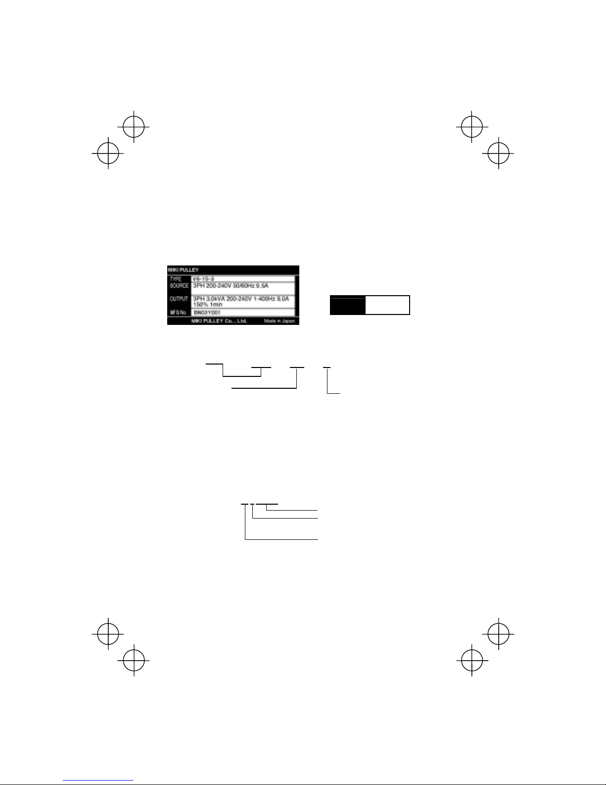
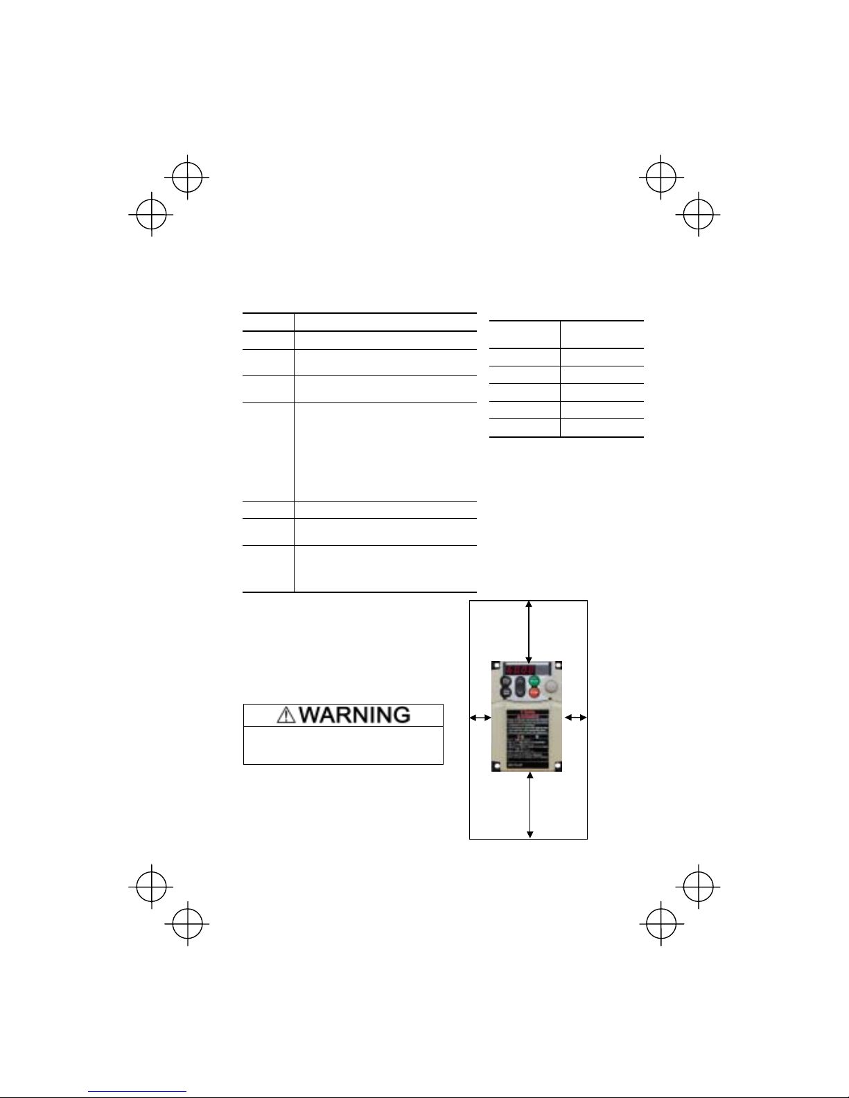
(3) The inverter is the model you ordered. You can check the model name and specifications on the
main nameplate. (Main and sub nameplates are attached to the inverter and are located as
shown on the following page.)
(a) Main Nameplate (b) Sub Nameplate
Figure 1.1 Nameplates
TYPE: Type of inverter
Code Series name
FRN V6 series
Code Assemble motor rating
01 0.1 kW
02 0.2 kW
04 0.4 kW
07 0.75 kW
15 1.5 kW
22 2.2 kW
37 3.7 kW
SOURCE: Number of input phases, input voltage, input frequency, input current
OUTPUT: Number of output phases, rated output capacity, rated output voltage, output
frequency range, rated output current, overload capacity
MFG. No.: Product number
BN03
Z 01- 001
Serial number of production lot
Production month
1 to 9: January to September
X, Y, or Z: October, November, or December
Production year: Last digit of year
If you suspect the product is not working properly or if you have any questions about your product,
contact your MikiPulley representative.
TYPE
MFG No.
V6-15-3
BN03Y001
Code Brake
3 W/O Braking
4 Braking resistor built-in type
V 6 - 01 - 4
1-2
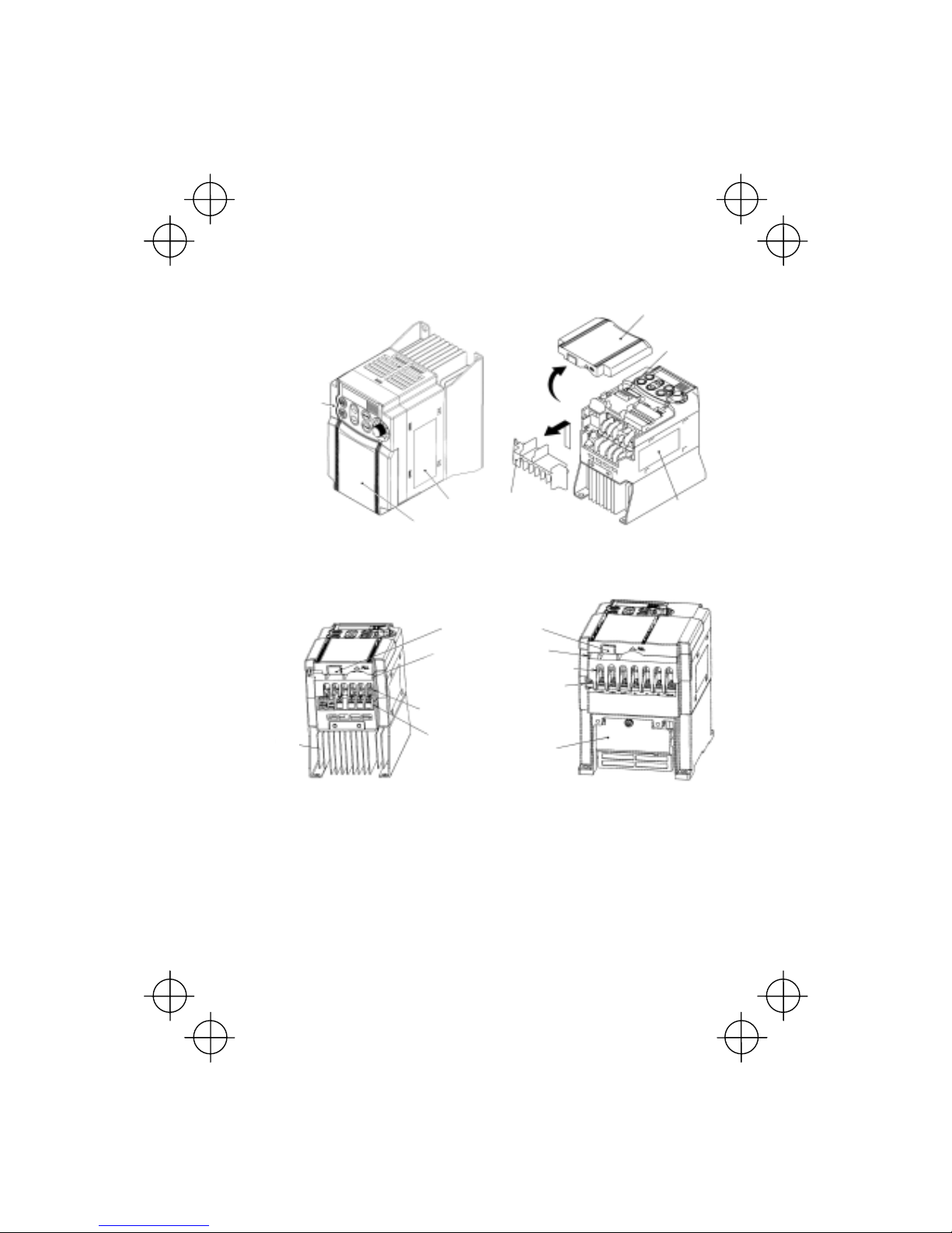
1.2 External View and Terminal Blocks
(1) External views
Figure 1.2 External Views of V6
(2) View of terminals
(a) V6-07-4 (b) V6-15-3
(* When connecting the RS485 communications cable, remove the control
circuit terminal block cover and cut off the barrier provided in it using nippers.)
Figure 1.3 Bottom View of V6
1.3 Transportation
• When carrying the inverter, always support its bottom at the front and rear sides with both hands.
Do not hold covers or individual parts only. You may drop the inverter or break it.
• Avoid applying excessively strong force to the terminal block covers as they are made of plastic
and are easily broken.
Barrier for the RS485
communications port*
Control signal cable port
Cooling
fan
L1/R, L2/S, L3/T, P1, P (+), N (-)
wire port
L1/R, L2/S, L3/T, U, V, W,
grounding wire port
DB, U, V, W,
grounding wire por
t
Heat
sink
DB, P1, P (+) and N (-) wire port
Keypad
Main
nameplate
Control circuit
terminal bock cover
Control circuit
terminal block
cover
Main circuit
terminal block
cover
Sub
nameplate
Main
nameplate

1-3
1.4 Storage Environment
1.4.1 Temporary storage
Store the inverter in an environment that satisfie s the requirements listed in T able 1.1.
Table 1.1 Environmental Requirements for Storage and Transportation
Item Requirements
Storage
temperature *
1
-25 to +70°C
Relative
humidity
5 to 95% *2
Locations where the inverter is not
subject to abrupt changes in
temperature that would result in the
formation of condensation or ice.
Atmosphere The inverter must not be exposed to dust, direct sunlight, corrosive or flammable
gases, oil mist, vapor, water drops or vibration. The atmosphere must contain only a
low level of salt. (0.01 mg/cm
2
or less per year)
86 to 106 kPa (in storage) Atmospheric
pressure
70 to 106 kPa (during transportation)
*
1
Assuming a comparatively short storage period (e.g., during transportation or the like).
*
2
Even if the humidity is within the specified requireme nts, avoid such places where the inverter will be
subjected to sudden changes in temperature that will cause condensation to form.
Precautions for temporary storage
(1) Do not leave the inverter directly on the floor.
(2) If the environment does not satisfy the specified requirements, wrap the inverter in an airtight
vinyl sheet or the like for storage.
(3) If the inverter is to be stored in an environment with a high level of humidity, put a drying agent
(such as silica gel) in the airtight package described in item (2).
1.4.2 Long-term storage
The long-term storage methods for the inverter vary largely according to the environment of the
storage site. General storage methods are described below.
(1) The storage site must satisfy the requirements specified for temporary storage.
However, for storage exceeding three months, the ambient temperature should be within the
range from -10 to +30 °C. This is to prevent the electrolytic capacitors in the inverter from
deteriorating.
(2) The inverter must be stored in a package that is airtight to protect it from moisture. Include a
drying agent inside the package to maintain the relative humidity inside the package to within
70%.
(3) If the inverter has been installed in the equipment or control board at a constr uction si te w here it
may be subjected to humidity, dust or dirt, then remove the inverter and store it in a suitable
environment specified in Table 1.1.
Precautions for storage over 1 year
If the inverter will not be powered on for a long time, the property of the electrolytic capacitors may
deteriorate. Power the inverters on once a year and keep them on for 30 to 60 minutes. Do not
connect the inverters to motors or run the motor.
2-1
Top 100 mm
Bottom 100 mm
Left
10 mm
Right
10 mm
Chapter 2 MOUNTING AND WIRING OF THE INVERTER
2.1 Operating Environment
Install the inverter in an environment that satisfies the requirements listed in Table 2.1.
Table 2.1 Environmental Requirements
Item Specifications
Site location Indoors
Ambient
temperature
-10 to +50°C (Note 1)
Relative
humidity
5 to 95% (No condensation)
Atmosphere
The inverter must not be exposed to dust,
direct sunlight, corrosive gases, flammable
gas, oil mist, vapor or water drops.
(Note 2)
The atmosphere must contain only a low
level of salt.
(0.01 mg/cm
2
or less per year)
The inverter must not be subjected to sudden
changes in temperature that will cause
condensation to form.
Altitude 1,000 m max. (Note 3)
Atmospheric
pressure
86 to 106 kPa
3 mm (Max. amplitude) 2 to less than 9 Hz
9.8 m/s2 9 to less than 20 Hz
2 m/s2 20 to less than 55 Hz
Vibration
1 m/s
2
55 to less than 200 Hz
2.2 Installing the Inverter
(1) Mounting base
The temperature of the heat sink will rise up to
approx. 90°C during operation of the inverter, so
the inverter should be mounted on a base made
of material that can withstand temperatures of this
level.
Install the inverter on a base constructed from
metal or other non-flammable material.
A fire may result with other material.
(2) Clearances
Ensure that the mi nimum c leara nces ind icat ed in
Figure 2.1 are maintained at all times. When
installing the inverter in the enclosure of you
r
system, take extra care with ventilation inside the
enclosure as the temperature around the inverte
r
will tend to increase.
Table 2.2 Output Current Derating Factor in
Relation to Altitude
Altitude
Output current
derating factor
1000 m or lower 1.00
1000 to 1500 m 0.97
1500 to 2000 m 0.95
2000 to 2500 m 0.91
2500 to 3000 m 0.88
(Note 1) When inverters are mounted
side-by-side without any gap between them
or the NEMA1 kit option is mounted on the
inverter, the ambient temperature should be
within the range from -10 to +40°C.
(Note 2) Do not install the inverter in an
environment where it may be exposed to
cotton waste or moist dust or dirt which will
clog the heat sink in the inverter. If the
inverter is to be used in such an env ironment,
install it in the enclosure of your system or
other dustproof containers.
(Note 3) If you use the inverter in an altitude
above 1000 m, you should apply an output
current derating factor as listed in Table 2.2.
Figure 2.1 Mounting Direction and
Required Clearances
2-2
When mounting two or more inverters
Horizontal layout is recommended when tw o or more inv erters are to b e inst all ed i n the same unit or
enclosure. As long as the ambient temperature is 40°C or lower, inverters may be mounted
side-by-side without any gap between them. If it is necessary to mount the inv erters v ertica lly, install
a partition plate or the like between the inverters so that any heat radiating from an inverter will not
affect the one/s above.
(3) Mounting direction
Secure the inverter to the mounting base with four screws or bolts (M4) so that the V6 Series logo
faces outwards. Tighten those screws or bolts perpendicular to the mounting base.
Do not mount the inverter upside down or horizontally. Doing so will reduce the heat
dissipation efficiency of the inverter an d cause the ov erheat pro tection fun ctio n to opera te,
so the inverter will not run.
Prevent lint, paper fibers, sawdust, dust, metallic chips, or other foreign materials from getting
into the inverter or from accumulating on the heat sink.
This may result in a fire or accident.
2.3 Wiring
Follow the procedure below. (In the following description, the inverter has already been installed.)
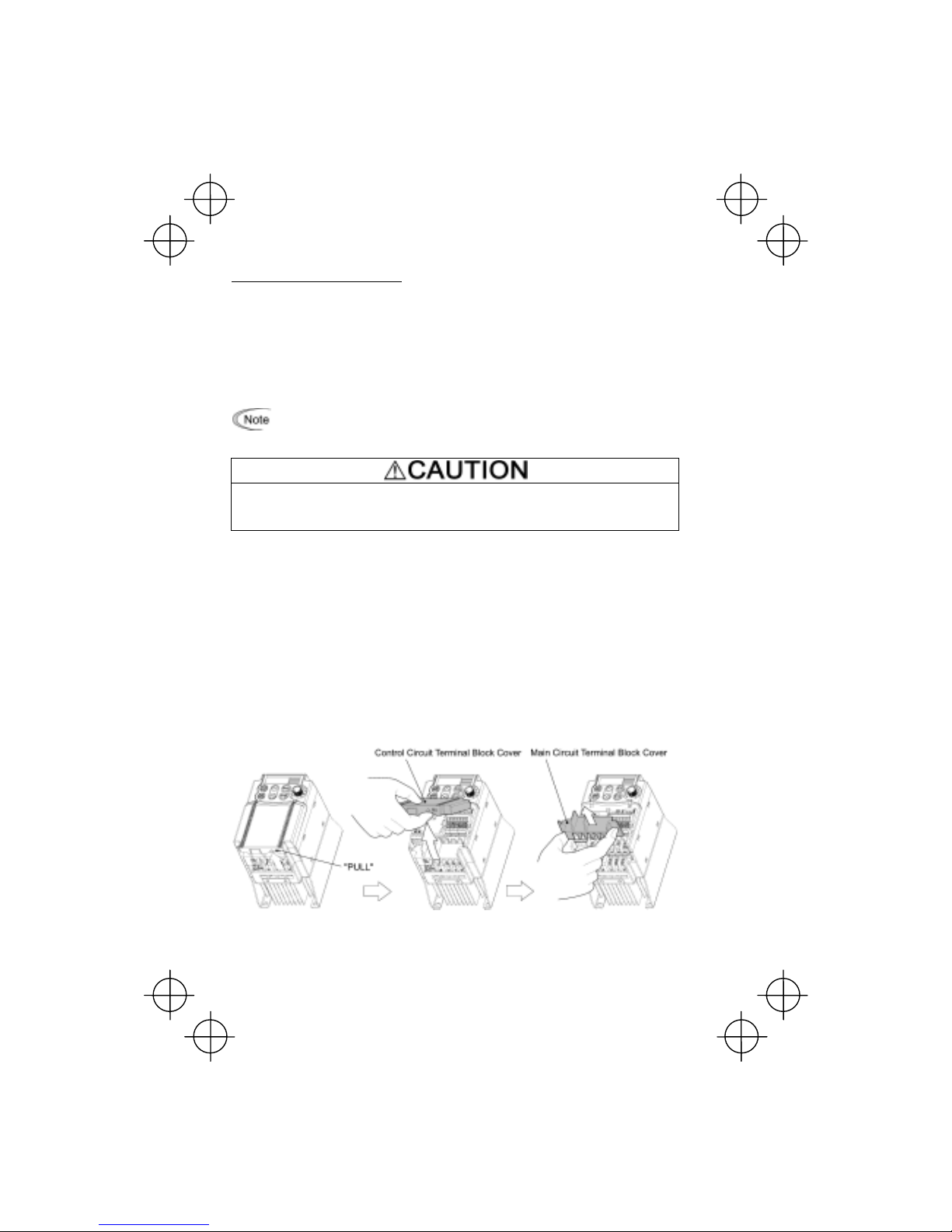
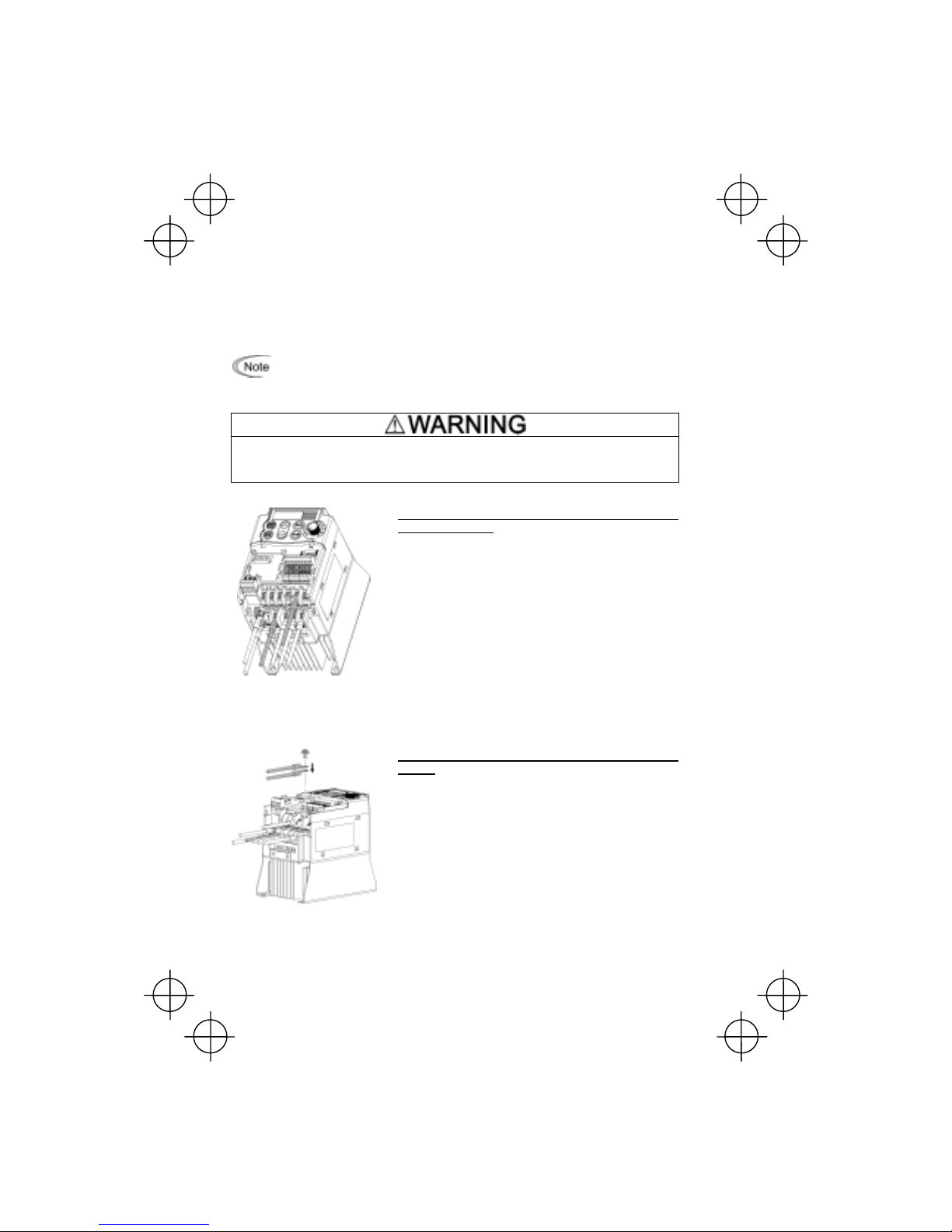
2.3.1 Removing the terminal b lock (TB) covers
(1) Removing the control circuit terminal block (TB) cover
Insert your finger in the cutout (near "PULL") in the bottom of the control circuit TB cover, then pull
the cover towards you.
(2) Removing the main circuit terminal block (TB) cover
Hold both sides of the main circuit TB cover between thumb and forefinger and slide it towards you.
Figure 2.2 Removing the Terminal Block (TB) Covers

2-3
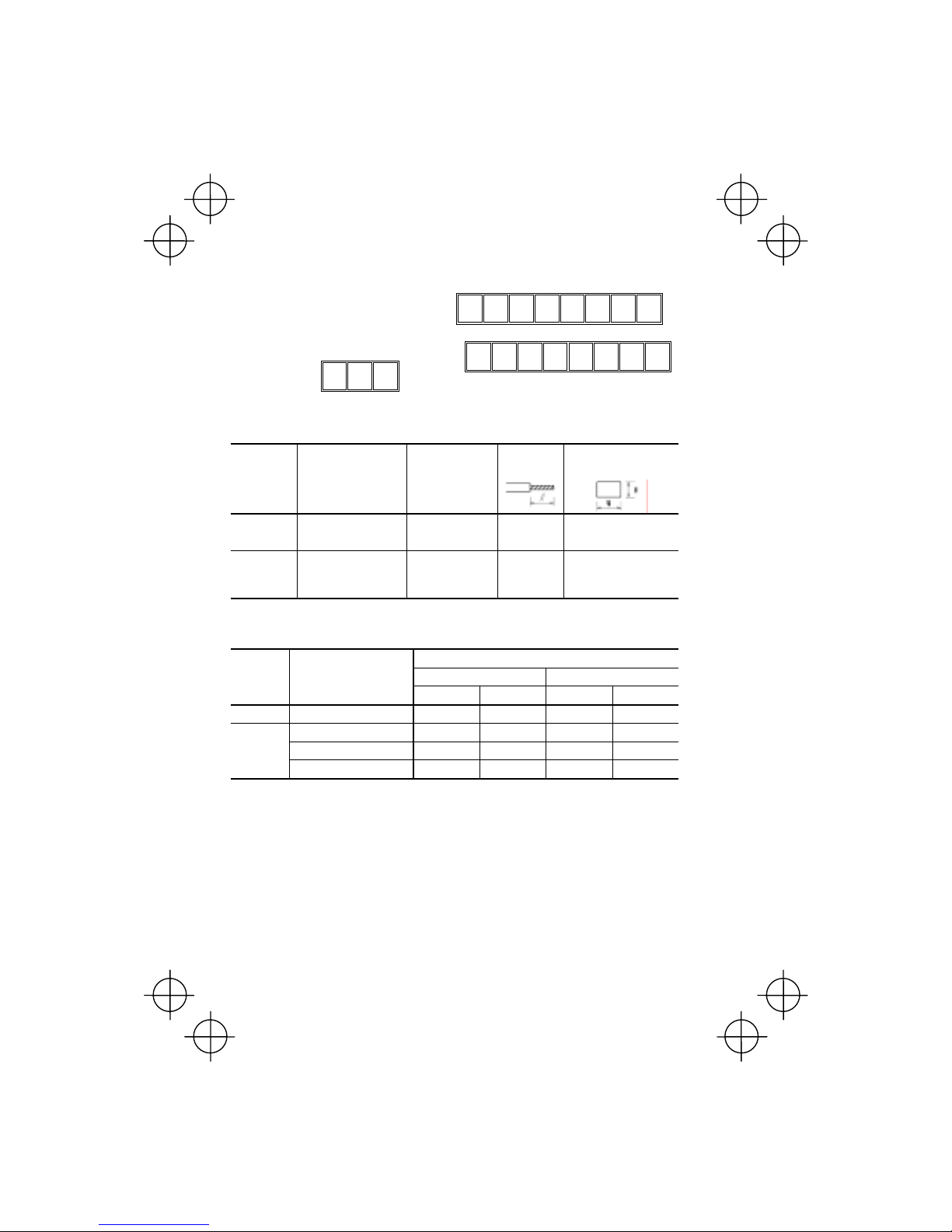
2.3.2 Terminal arrangement and screw specifications
The figures below show the arrangement of the main and control circuit terminals which differs
according to inverter type. The two terminals prepared for grounding, which are indicated by the
symbol
G in Figures A and B , make no distin ction be tw een the p ow er supply side (primary circuit)
and the motor side (secondary circuit).
(1) Arrangement of the main circuit terminals
Table 2.3 Main Circuit Terminals
Power
supply
voltage
Applicable
motor rating
(kW)
Inverter type
Terminal
screw size
Tightening
torque
(N·m)
Refer to:
0.1 V6-01-4
0.2 V6-02-4
0.4 V6-04-4
0.75 V6-07-4
M3.5 1.2 Figure A
1.5 V6-15-3**
2.2 V6-22-3**
Three-
phase
200 V
3.7 V6-37-3**
M4 1.8 Figure B
Note: Braking resistor built-in type: V6-15-3,V6-22-3,V6-37-3
2-4
(2) Arrangement of the control circuit terminals (common to all V6 models)
Screw size: M 2 Tightening torque: 0.2 N•m
Screw size: M 2.5 Tightening torque: 0.4 N•m
30A 30B 30C
Y111Y1E FMA C1 PLC
12 13 11 CM
X1 X2 X3
CM FWD REV
Table 2.4 Control Circuit Terminals
Terminal Screwdriver to be used Allowable wire size
Bared wire
length
Dimension of openings in
the control circuit terminals for stick terminals*
30A, 30B, 30C
Phillips screwdriver
(JIS standard)
No.1 screw tip
AWG22 to AWG18
(0.34 to 0.75 mm
2
)
6 to 8 mm 2.7 mm (W) x 1.8 mm (H)
Others
Phillips screwdriver for
precision machinery
(JCIS standard)
No.0 screw tip
AWG24 to AWG18
(0.25 to 0.75 mm
2
)
5 to 7 mm 1.7 mm (W) x 1.6 mm (H)
* Manufacturer of stick terminals: WAGO Company of Japan, Ltd. Refer to Table 2.5.
Table 2.5 Recommended Stick Terminals
Type (216-
)
Screw size Wire size
With insulated collar Without insulated collar
Short type Long type Short type Long type
M2
AWG24 (0.25 mm
2
) 321 301 151 131
AWG22 (0.34 mm
2
) 322 302 152 132
M2 or M2.5
AWG20 (0.50 mm
2
) 221 201 121 101
AWG18 (0.75 mm
2
) 222 202 122 102
The length of bared wires to be inserted into stick terminals is 5.0 mm or 8.0 mm fo r the shor t or lo ng t ype,
respectively.
The following crimping tool is recommended: Variocrimp 4 (Part No.: 206-204).
2.3.3 Recommended wire sizes
T able 2.6 list s the recommended wire sizes. The recommen ded wire sizes fo r the main circui ts for a n
ambient temperature of 50°C are indicated for two types of wire: HIV single w ire (for 75 °C) (before a
slash (/)) and IV single wire (for 60°C) (after a slash (/)),
2-5
Table 2.6 Recommended Wire Sizes
*1
Recommended wire size (mm
2
)
Main circuit
Main circuit power input
[L1/R, L2/S, L3/T]
Grounding [
G]
Power supply voltage
Applicable
motor
rating
(kW)
Inverter type
w/ DCR*2w/o DCR
Inverter
output
[U, V, W]
DCR
[P1, P (+)]
Braking
resistor
[P (+), DB]
Control
circuit
0.1 V6-01-4
0.2 V6-02-4
0.4 V6-04-4
0.75 V6-07-4
1.5 V6-15-3
2.2 V6-22-3
2.0 / 2.0
(2.5)
2.0 / 2.0
(2.5)
2.0 / 2.0
(2.5)
Three-phase 200 V
3.7
V6-37-3
2.0 / 2.0
(2.5)
2.0 / 5.5
(2.5)
2.0 / 3.5
(2.5)
2.0 / 3.5
(2.5)
2.0 / 2.0
(2.5)
0.5
DCR: DC reactor
*1 Use crimp terminals covered with an i nsulated s heath or i nsulating tu be. Recomm ended wire sizes ar e
for HIV/IV (PVC in the EU).
*2 Wire sizes are calculated on the basis of input RMS current u nder the condition that the power su pply
capacity and impedance are 500 kVA and 5%, respectively.
*3 Insert the DC r eactor (DCR) in either of the primary power input lines. Refer to Chapter 1 0 for more
details.
Note: Braking resistor built-in type V6-15-3,V6-22-3,V6-37-3

2-6
2.3.4 Wiring precautions
Follow the rules below when performing wiring for the inverter.
(1) Make sure that the source voltage is within the rated voltage range specified o n the namepla te.
(2) Be sure to connect the power wires to the main circuit power input terminals L1/R, L2/S and
L3/T (for three-phase voltage input) of the inverter. If the power wires are connected to other
terminals, the inverter will be damaged when the power is turned on.
(3) Always connect the grounding terminal to prevent electric shock, fire or other disasters and to
reduce electric noise.
(4) Use crimp terminals covered with in sulated sleeves for the main circui t terminal wiring to ensure
a reliable connection.
(5) Keep the power supply wiring (primary circuit) and motor wiring (secondary circuit) of the main
circuit, and control circuit wiring as far away as possible from each other.
• When wiring the inverter to the power source, insert a recommended molded case circuit
breaker (MCCB) or residual-current-operated protective device (RCD)/earth leakage
circuit breaker (ELCB) (with overcurrent protection) in the path of power lines. Use the
devices within the related current range.
• Use wires in the specified size.
Otherwise, fire could occur.
• Do not use one multicore cable in order to connect several inverters with motors.
• Do not connect a surge killer to the inverter's output (secondary) circuit.
Doing so could cause fire.
• Be sure to connect the grounding wires without fail.
Otherwise, electric shock or fire could occur.
• Qualified electricians should carry out wiring.
• Be sure to perform wiring after turning the power off.
• Ground the inverter following Class C or Class D specifications or national/local electric
code, depending on the input voltage of the inverter.
Otherwise, electric shock could occur.
• Be sure to perform wiring after installing the inverter body.
Otherwise, electric shock or injuries could occur.
• Ensure that the number of input phases and the rated voltage of the product match the
number of phases and the voltage of the AC power supply to which the product is to be
connected.
Otherwise, fire or an accident could occur.
• Do not connect the power source wires to output terminals (U, V, and W).
• Do not connect a braking resistor to between terminals P (+) and N (-), P1 and N (-), P (+)
and P1, DB and N (-), or P1 and DB.
Doing so could cause fire or an accident.
2-7
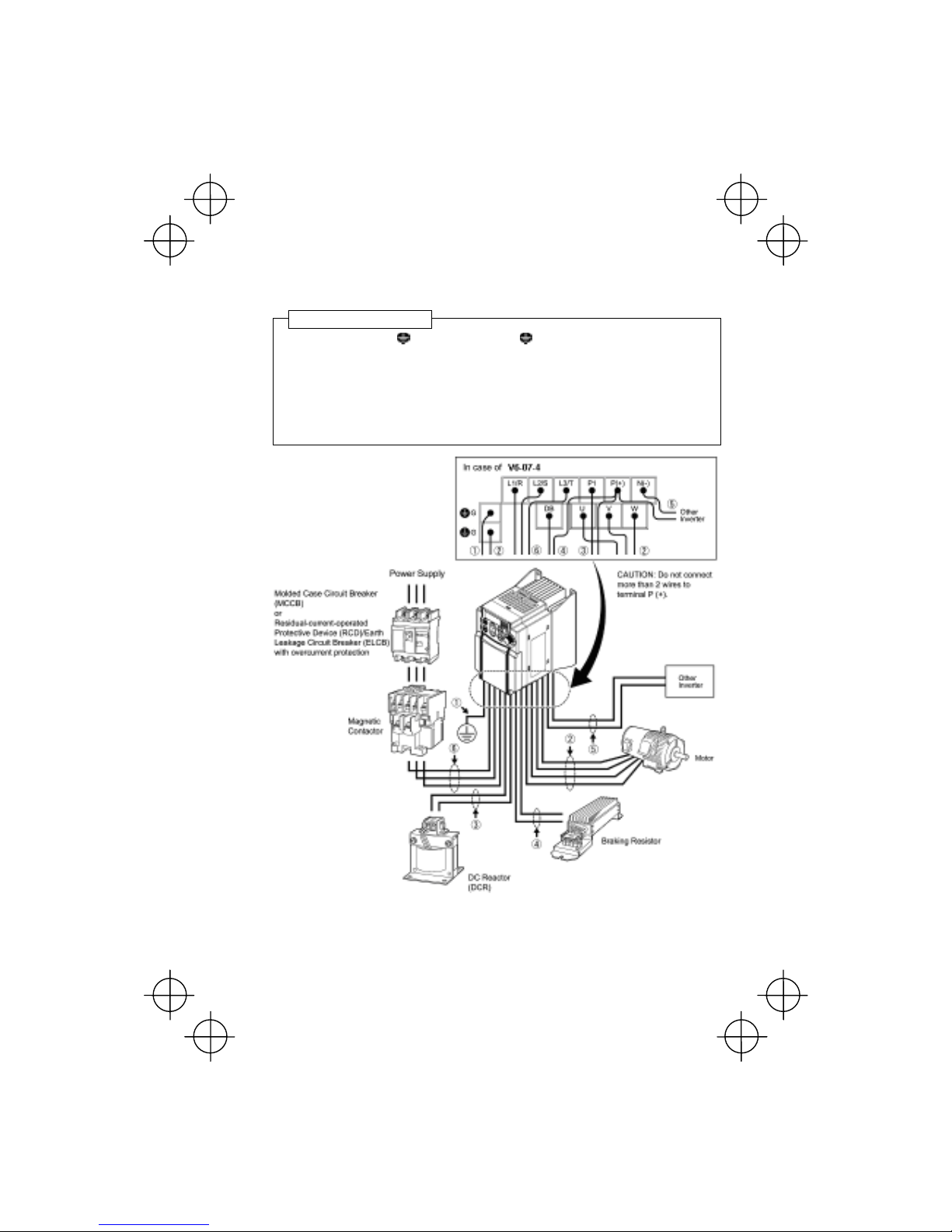
2.3.5 Wiring for main circuit terminals and grounding terminals
Follow the procedure below. Figure 2.3 illustrates the wiring procedure with peripheral equipment.
c Grounding terminal G (Use either one of the Gs.)
d Inverter output terminals (U, V, and W)
e DC reactor connection terminals (P1 and P(+))
*
f Braking resistor connection terminals (P(+) and DB)
*
g DC link circuit terminals (P(+) and N(-))
*
h Main circuit power input terminals (L1/R, L2/S and L3/T) or (L1/L and L2/N)
*Perform wiring as necessary.
Figure 2.3 Wiring Procedure for Peripheral Equipment
Wiring procedure
(This figure is a virtual representation.)

2-8
The wiring procedure for the V6-07-4 is given below as an e xample. For other inv erter types, perform
wiring in accordance with their individual terminal arrangement. (Refer to page 2-3.)
c Grounding terminals ( G)
Be sure to ground either of the two grounding terminals for safety and noise reduction. It i s stipulated
by the Electric Facility Technical Standard that all metal frames of electrical equipment must be
grounded to avoid electric shock, fire and other disasters.
Figure 2.4 Grounding Terminal
Wiring
Grounding terminals should be grounded as follows:
1) Connect the grounding terminal of inverters to a ground
electrode on which class D grounding work has been
completed, respectively, in compliance with the Electric Facility
Technical Standard.
2) Connect a thick grounding wire with a large surface area and
which meets the grounding resistance requirements listed in
Table 2.7. Keep the wiring length as short as possible.
Above requirements are for Japan. Ground the inverter
according to your national or local Electric code
requirements.
d Inverter output terminals, U, V, and W
1) Connect the three wires of the 3-phase motor to terminals U, V,
and W, aligning phases each other.
2) Connect the grounding wire of terminals U, V, and W to the
grounding terminal (
G).
Figure 2.5 Inverter Output
Terminal Wiring
- The wiring length between the inverter and moto
r
should not exceed 50 m.
-
Do not use one multicore cable to connect several
inverters with motors.
Table 2.7 Grounding Stipulated in the Electric Facility Technical Standard
Supply voltage Grounding work class Grounding resistance
3-phase 200 V Class D 100 Ω or less
Motor
50 m or less
Power
supply
Inverter

2-9
• Do not connect a power factor correcting capacitor or surge absorber to the inverter’s
output terminals (secondary circuit).
• If the wiring length is long, the stray capacitance between the wires will increase,
resulting in an outflow of the leakage current. It will activ ate the overcurre nt protection,
increase the leakage current, or will not assure the accuracy of the current display. In
the worst case, the inverter could be damaged.
• If more than one motor is to be connected to a single inv erter, the wiring length should
be the length of the wires to the motors.
e DC reactor terminals, P1 and P (+)
1) Remove the jumper bar from terminals P1 and P(+).
2) Connect a DC reactor (option) to terminals P1 and P(+).
• The wiring length should be 10 m or below.
• If both a DC reactor and a braking resistor are to be connected to the inverter, secure
both wires of the DC reactor and braking resistor together to terminal P(+). (Refer to
item
f on the next page.)
• Do not remove the jumper bar if a DC reactor is not going to be used.
Figure 2.6 DC Reactor Connection
2-10
f Braking resistor terminals, P(+) and DB
1) Connect terminals P and DB of a braki ng resistor to termin als P(+) and DB on the main circui t
terminal block. (For the braking resistor built-in type, refer to the next page.)
2) When using an external braking resistor, arrange the inverter and braking resi stor to keep the
wiring length to 5 m or less and twist the two wires or route them together in parallel.
Do not connect a braking resistor to any inverter with a rated capacity of 0.2 kW or below.
(Even if connected, the braking resistor will not work.)
Never insert a braking resistor between terminals P(+) and N(-), P1 and N(-), P(+) and P1, DB
and N(-), or P1 and DB.
Doing so could cause fire.
Figure 2.7 Braking Resistor
Connection without
DC Reactor
When a DC reactor is not to be connected together with
the braking resistor
1) Remove the screws from terminals P1 and P(+), togethe
r
with the jumper bar.
2) Put the wire from terminal P of the braking resistor and the
j
umper bar on terminal P(+) in this order, then secure them
with the screw removed in 1) above.
3) Tighten the screw on terminal P1.
4) Connect the wire from terminal DB of the braking resistor to
the DB of the inverter.
Figure 2.8 Braking Resistor
Connection with DC
Reactor
When connecting a DC reactor together with the braking
resistor
1) Remove the screw from terminal P(+).
2) Overlap the DC reactor wire and braking resistor wire (P)
as shown at left and then secure them to terminal P(+) o
f
the inverter with the screw.
3) Connect the wire from terminal DB of the braking resistor to
terminal DB of the inverter.
4) Do not use the jumper bar.
2-11
When using a braking resistor built-in type
A built-in braking resistor is connected to terminals P(+) and DB at the factory as shown below.
If you want to connect a DC reactor together with the
built-in braking resistor, follow the instructions given on
the previous page.
Figure 2.9 Built-in Braking Resistor
Connection
(This example shows the braking resistor
built-in type V6-15-3)
- If both wires of the built-in braking re si sto r
have been disconnected, you may
connect them to terminals P(+) and DB in
either combination.
- The braking resistor built-in type is
available only 1.5 kW or more.
Never insert a braking resistor between terminals P(+) and N(-), P1 and N(-), P(+) and P1, DB
and N(-), or P1 and DB.
Doing so could cause fire.
g DC link circuit terminals, P (+) and N (-)
These are provided for the DC link circuit system. Connect these terminals with terminals P(+) and N
(-) of other inverters.
Consult your Miki Pulley representative if these terminals are to be used.

2-12
h M ain cir cuit power input terminals, L1/R, L2/S, and L3/T (for three-phase voltage input)
1) For safety, make sure that the molded case circuit brea ke
r
(MCCB) or magnetic contactor (MC) is turned off before
wiring the main circuit power input terminals.
2) Connect the main circuit power supply wires (L1/R, L2/S
and L3/T) to the input terminals of the inverter via an
MCCB or residual-current-operated protective device
(RCD)
/
earth leakage circuit breaker (ELCB)*, and MC if
necessary.
It is not necessary to align phases of the power supply
wires and the input terminals of the inverter with each
other.
* With overcurrent protection
Figure 2.10 Main Circuit Power Input
Terminal Connection
It is recommended that a magnetic contactor be
inserted that can be manually activated. This is to
allow you to disconnect the inverter from the powe
r
supply in an emergency (e.g., when the protective
function is activated) so as to prevent a failure o
r
accident from causing the secondary problems.
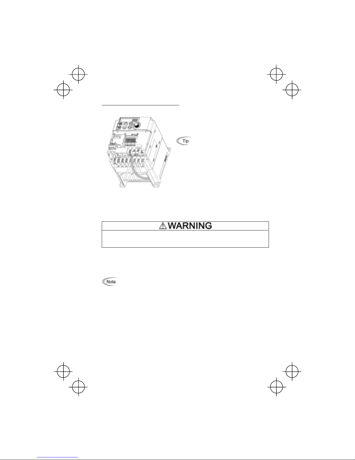
2.3.6 Replacing the main circuit terminal block (TB) cover
1) As shown in Figure 2.11, pull out the wires from the main circuit terminals in parallel.
2) Hold both sides of the main circuit TB cover between thumb and forefinger and slide it back
into place. Pull the wires out through the grooves of the main circuit TB cover.
Replace the main circuit TB cover , ta king care not to apply any stre ss to the wires. Apply ing
stress to the wires will impose a mechanical force on the screws on the main circuit
terminals, which may loosen the screws.
Figure 2.11 Putting Back the Main Circuit Terminal Block (TB) Cover

2-13
2.3.7 Wiring for control circuit terminals
In general, sheaths and covers of the control signal cables and wires are not specifically designed t o
withstand a high electric field (i.e., reinforced insulation is not applied). Therefore, if a control signal
cable or wire comes into direct contact with a live conductor of the main circuit, the insulation of the
sheath or the cover might break down, which would expose the signal wire to a high voltage of the main
circuit. Make sure that the control signal cables and wires will not come into contact with live conductors
of the main circuit.
Failure to observe these precautions could cause electric shock and/or an accident.
Noise may be emitted from the inverter, motor and wires.
Implement appropriate measure to prevent the nearby sensors and devices from malfun ctioning
due to such noise.
An accident could occur.
Figure 2.12 Example of Control
Circuit Wiring
Table 2.8 lists the symbols, names and functions of the
control circuit terminals. The wiring to the control circuit
terminals differs depending upon the setting of the function
codes, which reflects the use of the inverter.
Put back the main circuit TB cover and then conne ct w ires to
the control circuit terminals. As shown in Figure 2.12, pull the
wires out through the guides on the main circuit TB cover.
Route these wires correctly to reduce the influence of noise,
referring to the notes on the following pages.

2-14
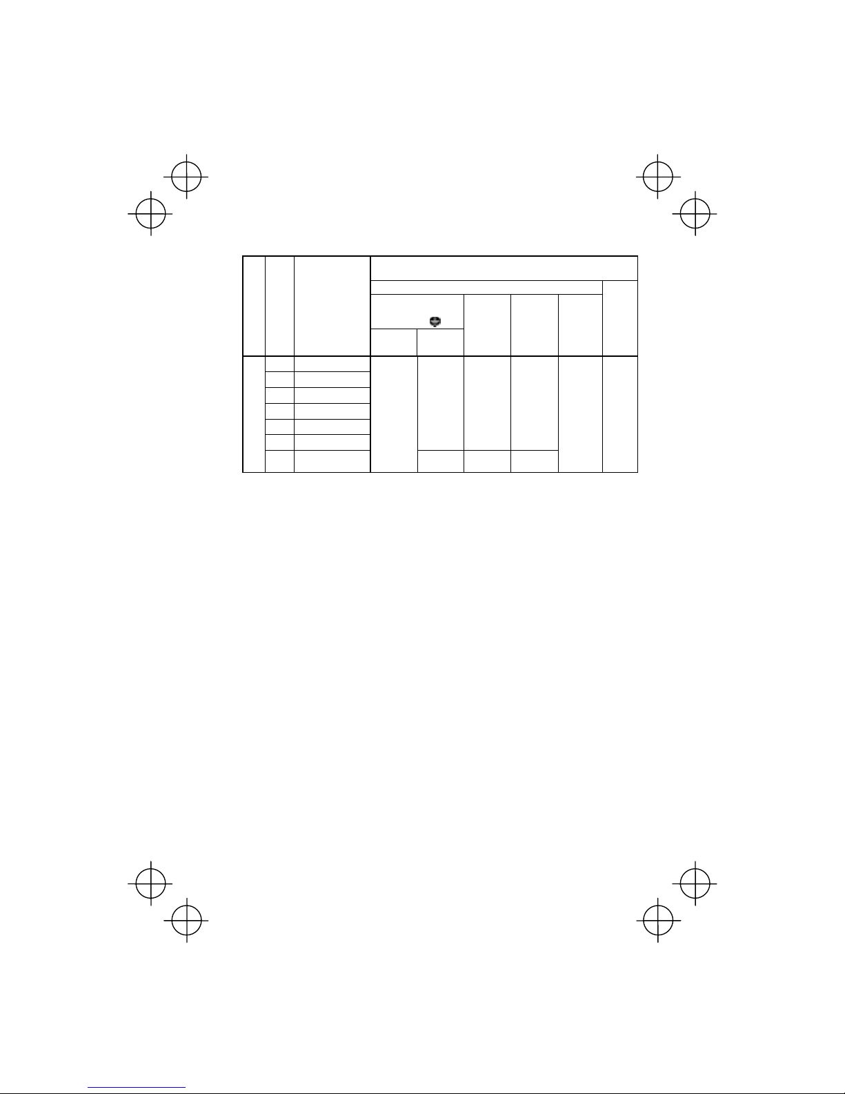
Table 2.8 Symbols, Names and Functions of the Control Circuit Terminals
Classifi-
cation
Symbol Name Functions
[13] Potenti-
ometer
power
supply
Power supply (+10 VDC) for frequency command potentiometer
(Potentiometer: 1 to 5 kΩ)
Allowable output current: 10 mA
[12] Voltage
input
(1) The frequency is set according to the external analog input voltage.
0 to +10 (VDC)/0 to 100 (%) (Normal mode operation)
+10 to 0 (VDC)/0 to 100 (%) (Inverse mode operation)
(2) Used for reference signal (PID process command) or PID feedback
signal.
(3) Used as additional auxiliary setting for various main frequency
commands.
* Input impedance: 22 kΩ
* Allowable maximum input voltage is +15 VDC. If the input voltage is +10
VDC or more, the inverter will limit it at +10 VDC.
[C1] Current
input
(1) The frequency is set according to the external analog input current
command.
+4 to +20 (mA DC)/0 to 100 (%) (Normal mode operation)
+20 to +4 (mA DC)/0 to 100 (%) (Inverse mode operation)
(2) Used for reference signal (PID process command) or PID feedback
signal.
(3) Connects PTC (Positive Temperature Coefficient) thermistor for motor
protection.
(4) Used as additional auxiliary setting to various main frequency
commands.
* Input impedance: 250 Ω
* Allowable input current is +30 mA DC. If the input current exceeds +20
mA DC, the inverter will limit it at +20 mA DC.
Analog input
[11] Analog
common
Common terminal for analog input and output signals
This terminal is electrically isolated from terminals [CM] and [Y1E].

2-15
Table 2.8 Continued
Classifi-
cation
Symbol Name Functions
- Since weak analog signals are handled, these signals are especially susceptible
to the external noise effects. Route the wiring as short as possible (within 20 m)
and use shielded wires. In principle, ground the shielding layer of the shielded
wires; if effects of external inductive noises are considerable, connection to
terminal [11] may be ef fectiv e. As shown in Figure 2.13 , ground the sin gle end of
the shield to enhance the shielding effect.
- Use a twin contact relay for weak signals if the relay is u sed in the con trol cir cuit.
Do not connect the relay's contact to terminal [11].
- When the inverter is connected to an external device outputting the analog
signal, a malfunction may be caused by electric noise generated by the inverter.
If this happens, according to the circumstances, connect a ferrite core (a toroidal
core or an equivalent) to the device outputting the analog signal and/or connect a
capacitor having the good cut-off characteristics for high frequency between
control signal wires as shown in Figure 2.14.
- Do not apply a voltage of +7.5 VDC or higher to terminal [C1]. Doing so could
damage the internal control circuit.
Analog input
Figure 2.13 Connection of Shielded Wire Figure 2.14 Example of Electric Noise Prevention

2-16
Item Min. Max.
ON level 0V 2V
Operation
voltage
(SINK)
OFF level 22V 27V
ON level 22V 27V
Operation
voltage
(SOURCE)
OFF level 0V 2V
Operation current at ON
(Input Voltage at 0 V)
2.5mA 5mA
Allowable leakage
current at OFF
- 0.5mA
Table 2.8 Continued
Classifi-
cation
Symbol Name Functions
[X1] Digital
input 1
[X2] Digital
input 2
[X3] Digital
input 3
[FWD] Forward
operation
command
[REV] Reverse
operation
command
(1) The various signals such as coast-to-stop, alarm from external
equipment, and multistep frequency selection can be assigned to
terminals [X1] to [X3], [FWD] and [REV] by setting function codes E01 to
E03, E98, and E99. For details, refer to Chapter 5, Section 5.2 "Overview
of Function Codes."
(2) Input mode, i.e. Sink/Source, is changeable by using the internal jumper
switch.
(3) Switches the logic value (1/0) for ON/OFF of the terminals between [X1]
to [X3], [FWD] or [REV], and [CM]. If the logic value for ON between [X1]
and [CM] is 1 in the normal logic system, for example, OFF is 1 in the
negative logic system and vice versa.
(4) The negative logic signaling cannot be applicable to [FWD] and [REV].
Digital input circuit specifications
[PLC] PLC
signal
power
Connects to PLC output signal power supply. (Rated voltage: +24 VDC,
Maximum output current: 50 mA)
Digital input
[CM] Digital
common
Common terminal for digital input signals
This terminal is electrically isolated from terminals [11] and [Y1E].

2-17
Table 2.8 Continued
Classifi-
cation
Symbol Name Functions
Turning on or off [X1], [X2], [X3], [FWD], or [REV] using a relay contact
Figure 2.15 shows two examples of a circuit that turns on or off control signal input [X1],
[X2], [X3], [FWD], or [REV] using a relay contact. Circuit (a) has a connecting jumper
applied to SINK, whereas circuit (b) has it applied to SOURCE.
NOTE: To configure this kind of circuit, use a highly reliable relay
(a) With a jumper applied to SINK
(b) With a jumper applied to SOURCE.
Figure 2.15 Circuit Configuration Using a Relay Contact
Turning on or off [X1], [X2], [X3], [FWD], or [REV] using a programmable logic
controller (PLC)
Figure 2.16 shows two examples of a circuit that turns on or off control signal in put [X1],
[X2], [X3], [FWD], or [REV] using a programmable logic controller (PLC). Circuit (a) has a
connecting jumper applied to SINK, whereas circuit (b) has it applied to SOURCE.
In circuit (a) below, short-circuiting or opening the transistor's open collector circuit in the
PLC using an external power source turns on or off control signal [X1], [X2], [X3], [FWD],
or [REV]. When using this type of circuit, observe the following:
- Connect the + node of the external po wer source (which should be isolated fro m the
PLC's power) to terminal [PLC] of the inverter.
- Do not connect terminal [CM] of the inverter to the common terminal of the PLC.
(a) With a jumper applied to SINK
(b) With a jumper applied to SOURCE
Digital input
Figure 2.16 Circuit Configuration Using a PLC
For details about the jumper setting, refer to Section 2.3.8 "Switching of
SINK/SOURCE (jumper switch)."

2-18
Table 2.8 Continued
Cl
ass
if
i
-
cation
Symbol Name Functions
[FMA] Analog
monitor
The monitor signal for analog DC voltage (0 to +10 VDC) is output. The
signal functions can be selected from the following with function code F31.
- Output frequency (before slip compensation)
- Output frequency (after slip compensation)
- Output current - Output voltage
- Input power - PID feedback amount
- DC link circuit voltage - Analog output test voltage (+)
*Input impedance of external device: Min. 5 kΩ
Analog output
[11] Analog
common
Common terminal for analog input and output signals
This terminal is electrically isolated from terminals [CM] and [Y1E].
(1) Various signals such as inverter running, speed/freq. arrival and
overload early warning can be assigned to the terminal [Y1] by setting
function code E20. Refer to Chapter 5, Section 5.2 "Overview of
Function Codes" for details.
(2) Switches the logic value (1/0) for ON/OFF of the terminals between [Y1]
and [Y1E]. If the logic value for ON between [Y1] and [Y1E] is 1 in th e
normal logic system, for example, OFF is 1 in the negative logic system
and vice versa.
Digital input circuit specification
Figure 2.18 shows examples of connection between the control circuit and
a PLC.
[Y1] Transistor
output
- Check the polarity of the external power inputs.
- When connecting a control relay, first connect a surge-absorbing
diode across the coil of the relay.
[PLC] Transistor
output
power
Power source of +24 VDC to be fed to the transistor output circuit load (50mA
at maximum).
To enable the source, it is necessary to short-circuit between terminals [Y1E]
and [CM].
Can also be used as a 24 VDC power source.
Transistor output
[Y1E] Transistor
output
common
Common terminal for transistor output signal
This terminal is electrically Isolated from terminals [CM] and [11].
Item Max.
ON level 2V
Operation
voltage
OFF level 27V
Maximum load current
at ON
50mA
Leakage current at OFF
0.1mA

2-19
Table 2.8 Continued
Classifi-
cation
Symbol Name Functions
Connecting Programmable Controller (PLC) to Terminal [Y1]
Figure 2.18 shows two examples of circuit connection between the transistor output of the
inverter’s control circuit and a PLC. In example (a), the input circuit of the PLC serves as
the sink for the control circuit, whereas in example (b), it serves as the source for the
control circuit.
(a) PLC serving as Sink
(b) PLC serving as Source
Transistor output
Figure 2.18 Connecting PLC to Control Circuit
[30A],
[30B],
[30C]
Alarm
relay
output
(for any
fault)
(1) Outputs a contact signal (SPDT) when a protective function has been
activated to stop the motor.
Contact rating: 250 VAC 0.3A cos φ = 0.3
+48 VDC, 0.5A
(2) A command similar to terminal [ Y1] can be selected for the transistor
output signal and use it for signal output.
(3) Switching of the normal/negative logic output is applicable to the
following two contact outputs: "Terminals [30A] and [30C] are
short-circuited for ON signal output" or "the terminals [30B] and [30C]
are short-circuited (non-excite) for ON signal output."
Communication
RS485
port*
RS485
communications I/O
(1) Used to connect the inverter with PC or PLC using RS485 port.
(2) Used to connect the inverter with the remote keypad. The inverter
supplies the power to the remote keypad through the extension cable
for remote keypad.
*
This terminal can be used with standard inverters equipped with an RS485 Communications Card (option).
-
Route the wiring of the control terminals as far from the wiring of the main circuit as
possible. Otherwise electric noise may cause malfunctions.
-
Fix the control circuit wires inside the inverter to keep them away from the live parts of
the main circuit (such as the terminal block of the main circuit).
Relay contact output

2-20
2.3.8 Switching of SINK/SOURCE (jumper switch)
Before changing the jumper switch, wait fo r at least fiv e minutes after the power h as been turned
off, then check that the DC link circuit voltage between the terminals P (+) and N (-) does not
exceed the safety voltage (+25 VDC) using a multi-meter.
An electric shock may result if this warning is not heeded as there may be some residual
electric charge in the DC bus capacitor even after the power has been turned off.
Figure 2.19 Switching of SINK/SOURCE (Jumper Switch)
To switch the sink/source of the digital
input signal, change the position of the
jumper switch using a pair of long-nose
pliers, as shown in Figure 2.19.
At the factory setting, the jumper switch
is positioned at SINK for the Asian and
Japanese versions.
2.3.9 Installing an RS485 communications card (option)
Figure 2.20 Installing an RS485 Communications Card
(Option)
When an optional RS485
Communications Card is to be used,
install it before putting back the control
circuit TB cover. Align the card with the
latch on the inverter and attach the card
to the connector that is located above
terminals [30A], [30B] and [30C].

2-21
• Before installing an RS485 Communications Card, turn off the power, w ait more than fiv e
minutes, and make sure, using a circuit tester or a similar instrument, that the DC link
circuit voltage between the terminals P (+) and N (-) has dropped below a safe voltage
(+25 VDC).
• Do not remove the terminal cover for the control circuits while power is applied, because
a high voltage exists on the RS485 Communications Card.
Failure to observe these precautions could cause electric shock.
• In general, sheaths and covers of the control signal cables and wires are not specifically
designed to withstand a high electric field (i.e., reinforced insulation is not applied).
Therefore, if a control signal cable or wire comes into direct contact with a live conductor
of the main circuit, the insulation of the sheath or the cover might break down, which
would expose the signal wire to a high voltage of the main circuit. Make sure that the
control signal cables and wires will not come into contact w ith live condu ctors of the main
circuit.
Failure to observe these precautions could cause electric shock and/or an
accident.
2.3.10 Replacing the control circuit terminal block (TB) cover
Upon completion of the wiring of the control circuits, fit the latches provided on the upper end of the
control circuit TB cover into the openings in the front face of th e inverter, and then close the TB cover
as shown in Figure 2.21.
NOTE: Take care not to pinch the control signal wires between the TB cover and inverter body.
(*When connecting an extension cable for remote operation or an off-the-shelf L AN cable, snip off the
barrier of the RS485 communications cable port using nippers.)
Figure 2.21 Putting Back the Control Circuit Terminal Block (TB) Cover

2-22
2.3.11 Cautions relating to harmonic component, noise, and leakage current
(1) Harmonic component
Input current to an inverter includes a harmonic component, which may affect other loads and
condensive capacitors that are connected to the same power source as the i nv erter. If the harmonic
component causes any problems, connect a DC reactor (option) to the inverter. It may also be
necessary to connect an AC reactor to the condensive capacitors.
(2) Noise
If noise generated from the inverter affects other devices, or that generated from peripheral
equipment causes the inverter to malfunction, follow the basic measures outlined below.
1) If noise generated from the inverter affects the other devices through power wires or grounding
wires:
- Isolate the grounded metal frames of the inverter from those of the other devices.
- Connect a noise filter to the inverter power wires.
- Isolate the power system of the other devises from that of the inverter with an insulated
transformer.
2) If induction or radio noise generated from the inverter a ffect s othe r dev ices through pow er wires
or grounding wires:
- Isolate the main circuit wires from the control circuit wires and other device wires.
- Put the main circuit wires through a metal conduit and connect the pipe to the ground near the
inverter.
- Mount the inverter onto the metal board and connect the whole board to the ground.
- Connect a noise filter to the inverter power wires.
3) When implementing measures against noise generated from peripheral equipment:
- For the control signal wires, use twisted or shielded-twisted wires. When using
shielded-twisted wires, connect the shield of the shielded wires to the common terminals of
the control circuit.
- Connect a surge absorber in parallel with a coil or solenoid of the magnetic contactor.
(3) Leakage current
Harmonic component current generated by insulated gate bipolar transistors (IGBTs) switching
on/off inside the inverter becomes leakage current through stray capacitors of inverter input and
output wires or a motor . If any of the problems li sted below o ccur , take appropr iate measures agai nst
them.
Table 2.9 Leakage Current Countermeasures
Problem Measures
An earth leakage circuit
breaker* that is connected
to the input (primary) has
tripped.
* With overcurrent protection
1) Decrease the carrier frequency.
2) Make the wires between the inverter and motor shorter.
3) Use an earth leakage circuit breaker that has a larger
current sensitivity than one currently being used.
4) Use an earth leakage circuit breaker that features measures
against harmonic component.
An external thermal relay
was activated.
1) Decrease the carrier frequency.
2) Increase the settling current of the thermal relay.
3) Use the thermal relay built in the inverter.

3-1
Chapter 3 OPERATION USING THE KEYPAD
3.1 Keys, Potentiometer, and LED on the Keypad
As shown in the figure at right, the
keypad consists of a four-digit LED
monitor, a potentiometer (PO T), and
six keys.
The keypad allows you to start and
stop the motor, monitor running
status, and switch to the menu mode.
In the menu mode, you may set the
function code data, monitor I/O signal
states, maintenance information, and
alarm information.
Table 3.1 Overview of Keypad Functions
Monitor,
Potentiometer
and Keys
Functions
Four-digit, 7-segment LED monitor which displays the following according to the
operation modes *.
In Running mode: Running status information (e.g., output frequency,
current, and voltage)
In Programming mode: Menus, function codes and their data
In Alarm mode: Alarm code, which identifies the error factor if the
protective function is activated.
Potentiometer (POT) which is used to manually set frequency, auxiliary
frequencies 1 and 2 or PID process command.
RUN key. Press this key to run the motor.
STOP key. Press this key to stop the motor.
/
UP/DOWN keys. Press these keys to select the setting items and change the
function data displayed on the LED monitor.
Program/Reset key which switches the operation modes* of the inverter.
In Running mode: Pressing this key switches the inverter to
Programming mode.
In Programming mode: Pressing this key switches the inverter to Running
mode.
In Alarm mode: Pressing this key after removing the error factor will
switch the inverter to Running mode.
Function/Data key which switches the operation you want to do in each mode as
follows:
In Running mode: Pressing this key switches the information to be
displayed concerning the status of the inverter (output
frequency (Hz), output current (A), output voltage (V),
etc.).
In Programming mode: Pressing this key displays the function code and sets
the data entered with the
and keys or the POT.
In Alarm mode: Pressing this key displays the details of the problem
indicated by the alarm code that has come up on the
LED monitor.
* V6 features three operation modes: Running, Programming, and Alarm. Refer to Section 3.2 "Overview of
Operation Modes."
STOP key
Potentiometer RUN key LED monitor
Down key Up key Function/Data key
Program/Reset key

3-2
Simultaneous keying
Simultaneous keying means pressing two keys at the same time (expressed by "+"). V6 series
supports simultaneous keying as listed below.
(For example, the expression "
+ keys" stands for pressing the key while holding down the
key.)
Table 3.2 Simultaneous Keying
O
p
eration mode Simultaneouskeyin
g
Used to:
Running mode Control entry to/exit from jogging operation.
+ keys
Programming
mode
+ keys
Change certain function code data.
(Refer to codes F00, H03, and H97 in Chapter 5
"FUNCTION CODES.")
Alarm mode + keys
Switch to Programming mode without resetting
the alarm.
3.2 Overview of Operation Modes
V6 series features the following three operation modes:
■ Running mode : This mode allows you to enter run/stop commands in regular operation.
You can also monitor the running status in real time.
■ Programming mode : This mode allows you to set function code data and check a variety of
information relating to the inverter status and maintenance.
■ Alarm mode : If an alarm condition occurs, the inverter automatically enters the Alarm
mode. In this mode, you can view the corresponding alarm code* and its
related information on the LED monitor.
* Alarm code: Indicates the cause of the alarm condition that has triggered a protective function. For details,
refer to Chapter 8, Section 8.6 "Protective Functions."
Figure 3.1 shows the status transition of the inverter between these three operation modes.
Figure 3.1 Status Transition between Operation Modes
Figure 3.2 illustrates the transition of the LED monitor screen during the Running mode, the
transition between menu items in the Programming mode, and the transition b etween alarm codes a t
different occurrences in the Alarm mode.

3-3
*1 In speed monitor, you can have any of the following displayed according to the sett ing of function code
E48: Output Frequency (Hz), Set Frequency (Hz), Load Sha ft Speed (r/min), Line Speed (m/min), and
Constant Rate of Feeding Time (min)
*2 Applicable only when PID control is employed.
*3 Applicable only when timer operation is selected by the setting of function code C21.
*4 Applicable only when a remote keypad (optional) is installed.
Figure 3.2 Transition between Basic Display Figures by Operation Mode

3-4
3.2.1 Running mode
When the inverter is turned on, it automatically enters Running mode. In Running mode, you can:
(1) Monitor the running status (e.g., output frequency, output current);
(2) Set up the set frequency and others;
(3) Run/stop the motor and;
(4) Jog (inch) the motor.
[ 1 ] Monitoring the Running Status
In Running mode, the seven items listed below can be monitored. Immediately after the inverter is
turned on, the monitor item specified by function code E43 is displayed. Press the
key to switch
between monitor items.
Table 3.3 Monitor Items
Monitor Items
Display Sample on
the LED monitor
Meaning of Displayed Value
Function
Code E43
Speed monitor
(Hz, rpm, m/min, min)
Refer to Table 3.4. 0
Output current (A)
Detected output current.
A: alternative expression for A (ampere)
3
Output voltage (V)
Specified output voltage.
U: alternative expression for V (voltage)
4
Input power (kW)
Electric power input to the inverter.
P: alternative expression for kW (kilo watt)
9
PID process command
(Note 1)
(Note 2)
10
PID feedback amount
(Note 1)
(Note 3)
(PID process command or PID feedback
amount) × (PID display coefficient A – B) + B
PID display coefficients A and B: Refer to
function codes E40 and E41
12
Timer (s) (Note 1)
(Note 4)
Remaining effective timer count 13
(Note 1) The PID process command and PID feedback amount are displayed only under the PID control
using a process command (J01 = 1 or 2). Further, the timer (for timer operation) is only displayed
when the timer is enabled (C21 = 1).
“– – – –“ will be displayed when the respective mode (PID control, timer) is not in effect.
(Note 2) The dot in the lowest digit will blink.
(Note 3) The dot in the lowest digit will light.
(Note 4) A positive integer is displayed.

3-5
Figure 3.3 shows the procedure for selecting the desired monitor item and the sub-item for speed
monitoring.
*1 The speed monitor displays the output frequency (Hz), set frequenc y (Hz), load shaft speed (rpm), line
speed (m/min.), or constant rate of feeding time (min.), depending on the setting of function code E48.
*2 The PID-related information will appear only when the inverter is under PID control. When PID control is
not in effect (J01 = 0) while data of the function code E43 is 10 or 12, or immediately after power on,
“– – – –“ will be displayed.
*3 This will appear only when timer operation is enabled by function code C21. When timer operation is not
in effect (C21 = 0) while data of the function code E43 is 13, or immediately after power on, “– – – –“ will
be displayed.
Figure 3.3 Selecting Monitor Item and Speed Monitor Sub-item

3-6
Table 3.4 lists the display items for the speed monitor that can be chosen with function code E48.
Table 3.4 Display Items on the Speed Monitor
Speed monitor items
Function code
E48
Meaning of Displayed Value
Output frequency (before slip
compensation) (Hz)
(Factory default)
0 Before slip compensation
Output frequency (after slip
compensation) (Hz)
1 Frequency actually being output
Set frequency (Hz) 2 Final set frequency
Load shaft speed (rpm) 4 Displayed value = Output frequency (Hz) x E50*
Line speed (m/min) 5 Displayed value = Output frequency (Hz) x E50*
Constant rate of feeding time
(min)
6
Displayed value =
E39×frequency Output
E50
*
*
When the value is equal to or more than 10000, will be displayed. Output frequencies contained in
these formulas are output frequencies before slip compensation.
[ 2 ] Setting up the Set Frequency, etc.
You can set up the desired frequency command and PID process command by using the
potentiometer and
and keys on the keypad. You can also set up the set frequency as load
shaft speed, line speed, and constant rate of feeding time by setting function code E48.
Setting up the set frequency
Using the built-in potentiometer (factory default)
By setting function code F01 to "4: Enable the built-in potentiometer" (factory default), you can
specify the set frequency using the potentiometer.

3-7
Using the and keys
(1) Set function code F01 to "0: Keypad operation." This ca n be done only when the remote keypad
is in Running mode.
(2) Press the or key to specify the set frequency. The lowest digit will blink.
(3) If you need to change the set frequency, press the
or key again. The new setting will be
automatically saved into the inverter’s memory. It is kept there even while the inverter is powered off,
and will be used as the initial frequency next time the inverter is powered on.
• If you have set the function code F01 to "0: Keypad operation ( or key )" but have
selected a frequency setting other than the frequency 1 (i.e., the frequency 2, set it via
communications, or as a multistep frequency), then you cannot use the
or key for
setting the set frequency even if the remote keypad is in Running mode. Pressing eithe
r
of these keys will just display the currently selected set frequency.
• When you start specifying or changing the se t frequ ency o r any other parameter with the
or key, the lowest digit on the display will blink and start changing. As you are
holding the key down, blinking will gradually move to the u pper digit places and the uppe
r
digits will be changeable.
• If you press the
or key once and then hold down the key for more than 1
second after the lowest digit st arts blinki ng, blinking will move to the next upper digit place
to allow you to change the value of that digit ( cursor mov ement). This w ay y ou can ea sily
change the values of the higher digits.
• By setting function code C30 to "0: Keypad operation (
or key)" and selecting
frequency set 2 as the frequency setting method, you can also specify or change the set
frequency in the same manner using the
and keys.
Alternatively , you can set up the set frequency, etc. from other menu items, depending on the setti ng
of function code E48 (= 4, 5, or 6) "LED monitor details (Select speed monitor)" as shown in the
following table.
Table 3.5 LED Monitor and Frequency Setting (with Speed Monitor selected)
Setting of E48 (displayed on LED monitor)
(with Speed Monitor selected)
Set frequency display Conversion of displayed value
0: Output frequency
(before slip compensation)
Frequency setting
1: Output frequency
(after slip compensation)
Frequency setting
2: Set frequency Frequency setting
4: Load shaft speed Load shaft speed setting
E50×settingFrequency
5: Line speed Line speed setting
E50×settingFrequency
6: Constant rate of feeding time Constant rate of feeding
time setting
E39 settingFrequency
E50
×

3-8
Make setting under PID control
To enable PID control, you need to set function code J01 to 1 or 2.
Under the PID control, the items that can be set or checked with the
and keys are different
from those under regular frequency control, depending upon the current LED monitor setting. If the
LED monitor is set to the speed monitor (E43 = 0), you may access manual feed commands (Set
frequency) with the
and keys; if it is set to any other, you may access PID process command
with those keys.
Setting the PID process command with the built-in potentiometer
(1) Set function code E60 to "3: PID process command 1."
(2) Set function code J02 to "1: PID process command 1."
Setting the PID process command with the
and keys
(1) Set function code J02 to "0: Keypad operation."
(2) Set the LED monitor to something other than the speed monitor (E43 = 0) in Running mode.
This setting is possible only in Running mode.
(3) Press the
or key to have the PID process command displayed. The lowest digit will blink
on the LED monitor.
(4) T o change the P ID process command, press the
or key again. The PID process command
you have specified will be automatically sav ed into the inv erter’s memory. It is kept there even if you
temporarily switch to another means of specifying the PID process command and then go back to
the means of specifying the PID process command via the remote keypad. Al so, it is kept there even
while the inverter is powered off, and will be used as the initial PID process command next time the
inverter is powered on.
• Even if multistep frequency is selected as the PID process command ((SS4) = ON), y ou
still can set the process command using the remote keypad.
• When function code J02 data has been set to any v alue except 0, pressing the
or
key displays the PID process command currently selected (you cannot change the
setting).
• When a PID process command is displayed, the decimal p oint next to the low est digit on
the LED display blinks to distinguish it from the regular frequency setting. When a PID
feedback amount is displayed, the decimal point next to the lowest digit on the LED
display is lit.

3-9
Setting up the set frequency with the and keys under PID control
To set the set frequency with the
and keys under the PID control, you need to specify the
following conditions:
- Set function code F01 to "0: Keypad operation."
- Select frequency command 1 (Frequency settings from communications link: Disabled, and
Multistep frequency settings: Disabled) as manual speed command.
- Set the LED monitor to the speed monitor in Running mode.
The above setting is impossible in any operation mode except Running mode.
The setting procedure is the same as that for usual frequency setting.
If you press the
or key in any conditions other than those described above, the following will
appear:
Table 3.6 PID Process Command Manually Set with the / Key and Requirements
Frequency
command 1
(F01)
Frequency
setting via
communications link
Multistep
frequency
setting
PID control
cancelled
Display during
or key
operation
PID enabled
0 Disabled Disabled
Cancelled
Frequency setting by keypad
PID enabled
PID output (as final frequency
command)
Other than the above
Cancelled
Manual speed command currently
selected (frequency setting)
[ 3 ] Running/Stopping the Motor
By factory default, pressing the
key starts
running the motor in the forward direction and
pressing the
key decelerates the motor to
stop. The
key is enabled only in Running
mode.
By changing the setting of function code F02,
you can change the starting direction of motor
rotation; for example, you can have the motor
start running in the reverse direction or in
accordance with the wiring connection at the
terminal block.

3-10
Operational relationship between function code F02 (Running/Stopping and Rotational
Direction) and
key
T able 3.7 list s the relationship b etween function code F02 setti ngs and the key, which determines
the motor rotational direction.
Table 3.7 Rotational Direction of Motor, Specified by F02
If Function code F02
is set to:
Pressing the
key
rotates the motor:
2 in the forward direction
3 in the reverse direction
For the details of operation with function code F02 set to "0" or "1," refer to Chapter 5.
[ 4 ] Jogging (Inching) the Motor
To jog the motor, follow the procedure given below.
c Making the inverter ready for jogging (The
appears on the LED monitor.)
1) Switch to Running mode. (Refer to page 3-2 for details.)
2) Press the
+ keys at the same time (simultaneous keying).
The LED monitor will display the jogging frequency for approx. 1 second and go back to
the
display.
• During jogging, the jogging frequency specified by function code C20 and the
acceleration/deceleration time specified by function code H54 for jogging w ill apply.
They are exclusively prepared for jogging. Set these codes indiv idually as required.
• Using the external input signal "JOG" also allows the transition between the
ready-to-jog state and normal running state.
• The transition (
+ keys) between the ready-to-jog state and normal running
state is enabled only when the inverter is not in operation.
d Jogging the motor
1) The inverter will jog the motor only while the
key is held down, and contrarily the
moment the
key is released, the inverter will decelerate and stop the motor.
e Exiting the ready-to-jog state (Going back to normal running)
1) Press the
+ keys at the same time (simultaneous keying).

3-11
3.2.2 Programming mode
Programming mode provides you with these functions--setting and checking function code data,
monitoring maintenance information and checking input/output ( I/O) signal st atus. The functions can
be easily selected with the menu-driven system. Table 3.8 lists menus available in Programming
mode. The leftmost digit (numerals) of each letter string indicates the corresponding menu number
and the remaining three digits indicate the menu contents.
When the inverter enters Programming mode from the second time on, the menu that was selected
last in Programming mode will be displayed.
Table 3.8 Menus Available in Programming Mode
Menu # Menu
LED
monitor
shows:
Main functions
Refer
to:
F codes
(Fundamental functions)
E codes
(Extension terminal functions)
C codes
(Control functions of frequency)
P codes
(Motor parameters)
H codes
(High performance functions)
J codes
(Application functions)
#1
"Data setting"
y codes (Link functions)
Selecting each of
these function
codes enables its
data to be displayed/changed.
[1]
#2 "Data checking"
Displays only function codes that have been
changed from their factory defaults. You may refer to
or change those function codes data.
[2]
#3
"Drive monitoring"
Displays the running information required for
maintenance or test running.
[3]
#4
"I/O checking"
Displays external interface information.
[4]
#5
"Maintenance
information"
Displays maintenance information including
accumulated run time.
[5]
#6
"Alarm
information"
Displays the latest four alarm codes. You may refer
to the running information at the time when the alarm
occurred.
[6]
#7
"Data copying"
Allows you to read or write function code data, as
well as verifying it.*
--
* To use this function, you will need a remote keypad (option).

3-12
Figure 3.4 illustrates the menu transition in Programming mode.
* Displayed only when a remote keypad (option) is set up for use.
Figure 3.4 Menu Transition in Programming Mode

3-13
Limiting menus to be displayed
The menu-driven system has a limiter function (specified by function code E52) that limits menus to
be displayed for the purpose of simple operation. The factory default is to display Menu #1 "Data
setting" only, allowing no switching to any other menu.
Table 3.9 Function Code E52 – Keypad (Mode Selection)
Function code data (E52) Menus selectable
0: Function code data setting mode Menu #1 "Data setting" (factory default)
1: Function code data check mode Menu #2 "Data checking"
2: Full-menu mode Menu #1 through #6 (#7*)
* Menu #7 appears only when the remote keypad (option) is set up for use.
If the full-menu mode is selected, pressing the or key will cycle through the
menu. With the
key, you can select the desired menu item. Once the entire menu
has been cycled through, the display will return to the first menu item.
[ 1 ] Setting Function Codes – "Data Setting"
Menu #1 "Data setting" in Programming mode allows you to set function codes for making the
inverter functions match your needs.
To set function codes in Menu #1 "Data setting," it is necessary to set function code E52 data to "0"
(Function code data setting) or "2" (Full-menu mode).
The table below lists the function cod es av ailable in the V 6 serie s. The fun ction codes are di splay e d
on the LED monitor on the keypad as shown below.
Function code group
ID number in each function code group

3-14
Table 3.10 List of V6 Function Codes
Function code group Function code Function Description
F codes
(Fundamental functions)
F00 to F51 Basic
functions
To be used for basic motor running.
E codes
(Extension terminal
functions)
E01 to E99 Terminal
functions
To be used to select the functions of
the control circuit terminals.
To be used to set functions related to
the LED monitor display.
C codes
(Control functions of
frequency)
C01 to C52 Frequency
control
functions
To be used to set application functions
related to frequency settings.
P codes
(Motor parameters)
P02 to P99 Motor
parameters
To be used to set special parameters
for the motor capacity, etc.
H codes
(High performance
functions)
H03 to H98 High level
functions
To be used for high added value
functions and complicated control,
etc.
J codes
(Application functions)
J01 to J06 Application
functions
To be used for PID control.
y codes
(Link functions)
y01 to y99 Link functions To be used for communications
Refer to Chapter 5 "FUNCTION CODES" for details on the function codes.
Function codes that require simultaneous keying
To change data for function codes F00 (Protect data), H03 (Initialize data), and H97 (Clear alarm
data) simultaneous keying operation is necessary--
+ keys or + keys. This prevents
data from being lost by mistake.
Changing, validating, and saving function code data when the motor is running
Some function code data can be changed while the motor is running and some cannot. Further,
amongst the function codes whose data can be changed w hile the motor i s running, there are some
for which the changes can be validated immediately and others for which they cannot. Refer to the
"Change when running" column in Chapter 5, Section 5.1 "Function Code Tables."

3-15
Figure 3.5 shows the status transition for Menu #1 "Data setting."
Figure 3.5 "Data Setting" Status Transition

3-16
Basic key operation
This section will give a description of the basic key operation, following the example of the function
code data changing procedure shown in Figure 3.6.
This example shows you how to change function code F01 data from the facto ry default "Enable the
built-in potentiometer (F01 = 4)" to "Enable the
and keys on the built-in keypad (F01 = 0)."
(1) When the inverter is powered on, it automatically enters Running mode. In Running mode,
press the
key to enter Programming mode. The menu for function selection will be
displayed.
(2) With the menu displayed, use the
and keys to select the desired function code group. (In
this example, select ).
(3) Press the
key to display the function codes in the function code group selected in (2). (In this
example, function code
will appear.)
Even if the function code list for a particular function code group is displayed, it is possible to
transfer the display to a different function code group using the
and keys.
(4) Select the desired function code using the
and keys and press the key. (In this
example, select function code .)
The data of this function code will appear. (In this example, data " "
of will appear.)
(5) Change the function code data using the
and keys. (In this example, press the key
four times to change data to .)
(6) Press the
key to establish the function code data.
The
will appear and the data will b e saved in th e memory inside the inverter . The di splay
will return to the function code list, then mov e to the nex t function code. (In this ex ample, .)
Pressing the
key before the key ca ncel s the chan ge ma de to t he da ta. Th e data re ver ts
to the previous value, the display returns to the function code list, and the original fun ction code
reappears.
(7) Press the key to return to the menu from the function code list.
<Cursor movement>
You can move the cursor when changing function code data by holding down the
key
for 1 second or longer in the same way as with the frequency settings.
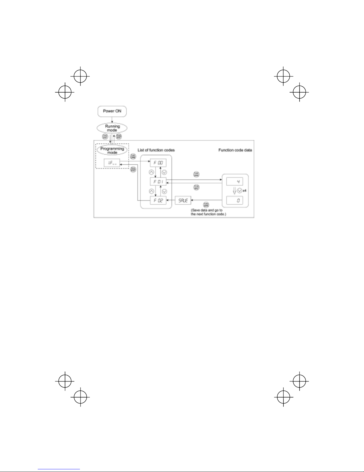
3-17
Figure 3.6 Example of Function Code Data Changing Procedure
[ 2 ] Checking Changed Function Codes – "Data Checking"
Menu #2 "Data checking" in Programming mode all ows you to check function codes that have been
changed. Only the function code for the data that has been changed from the factory defaults are
displayed on the LED monitor. You may refer to the function code data and change it again if
necessary. Figure 3.7 shows the status transition diagram for "Data checking."

3-18
* Pressing the
key when the data is displayed will take you back to .
Figure 3.7 "Data Checking" Status Transition (Changes made only to F01, F05, E52)
Basic key operation
The basic key operation is the same as for "Data setting."
To check function codes in Menu #2 "Data checking," it is necessary to set function code
E52 to "1" (Function code data check mode) or "2" (Full-menu mode).
For details, refer to "Limiting menus to be displayed" on page 3-13.

3-19
[ 3 ] Monitoring the Running Status – "Drive Monitoring"
Menu #3 "Drive monitoring" is used to check the running statu s during maintenance and test running.
The display items for "Drive monitoring" are listed in Table 3.11. Figure 3.8 shows the status
transition diagram for "Drive monitoring."
Figure 3.8 "Drive Monitoring" Status Transition
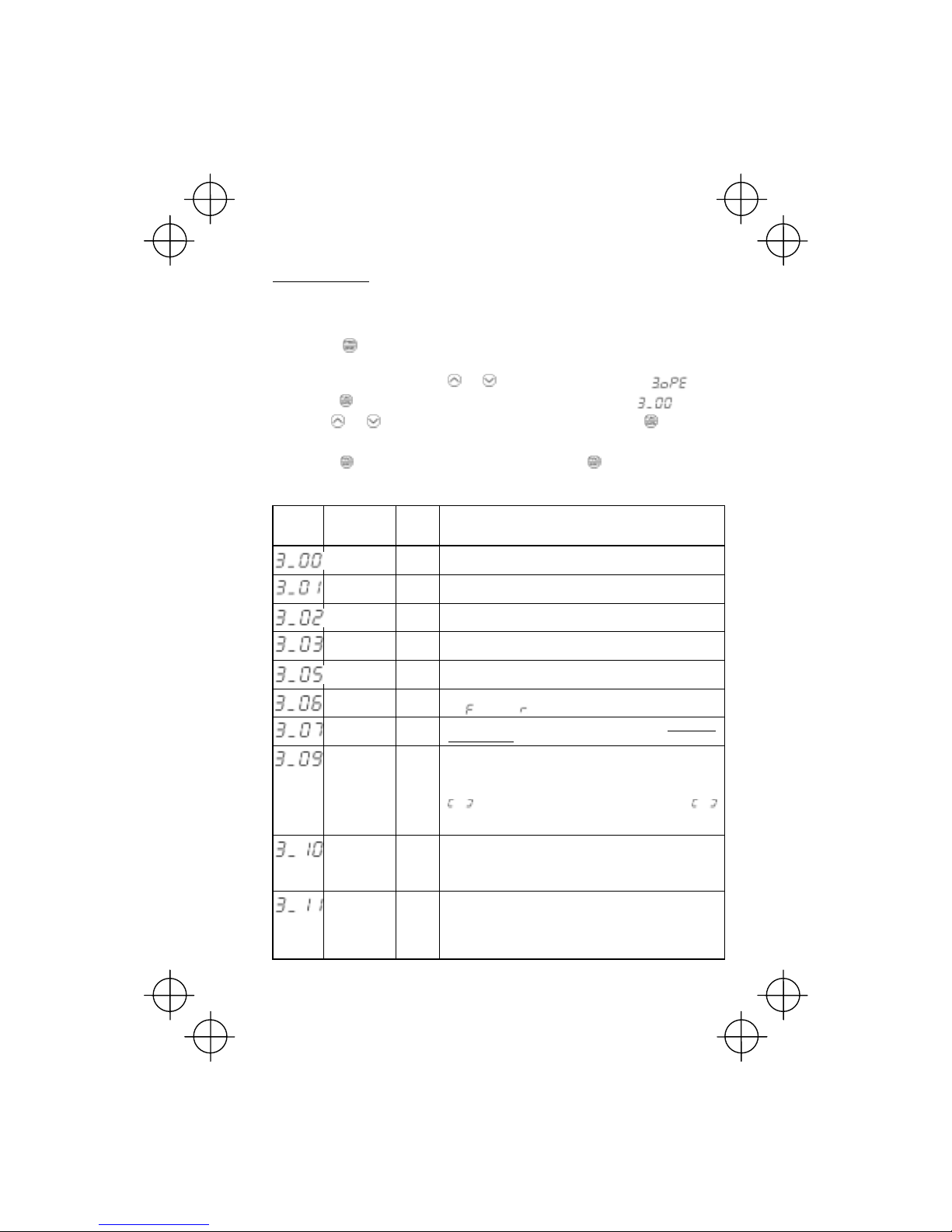
3-20
Basic key operation
Before checking the running status on the drive monitor, set function code E52 to "2" (full-menu
mode).
(1) When the inverter is powered on, it automatically enters Running mode. In Running mode,
press the
key to enter Programming mode. The menu for function selection will be
displayed.
(2) With the menu displayed, use the
and keys to select "Drive monitoring" ( ).
(3) Press the
key to display the desired code in the monitoring item list (e.g. ).
(4) Use the
and keys to select the desired monitoring item, then press the key.
The running status information for the selected item will appear.
(5) Press the
key to return to the monitoring item list. Press the key again to return to the
menu.
Table 3.11 Drive Monitoring Display Items
LED
monitor
shows:
Contents Unit Description
Output
frequency
Hz Output frequency before slip compensation
Output
frequency
Hz Output frequency after slip compensation
Output
current
A Output current
Output
voltage
V Output voltage
Set
frequency
Hz Set frequency
Running
direction
N/A Displays the running direction currently being outputted.
F: forward; R: reverse, – – – –: stop
Running
status
N/A Displays the running status in hex. format. Refer to "Displaying
running status" on the next page.
Load shaft
speed
(line speed)
rpm
(m/min)
The unit for load shaft speed is rpm and that for line speed is
m/min.
Display value = (Output frequency Hz before slip compensation)
× (Function code E50)
appears for 10000 (rpm or m/min) or more. When
appears, decrease function code E52 data so that the LED
monitor displays 9999 or below, referring to the above equation.
PID process
command
N/A The command is displayed through the use of function code E40
and E41 data (PID display coefficients A and B).
Display value = (PID process command) × (Coefficient A - B) + B
If PID control is disabled, "– – – –" appears.
PID feedback
amount
N/A This value is displayed through the use of function code E40
data and function code E41 data (PID display coefficients A and
B).
Display value = (PID feedback amount) × (Coefficient A - B) + B
If PID control is disabled, "– – – –" appears.

3-21
Displaying running status
T o display the runni ng st atus in hex adecimal format, e ach st ate has be en assi gned to bit s 0 to 15 as
listed in Table 3.12. Table 3.13 shows the relationship between each of the status assignments and
the LED monitor display. Table 3.14 gives the conversion table from 4-bit binary to hexadecimal.
Table 3.12 Running Status Bit Allocation
Bit Notation
Content
Bit Notation
Content
15 BUSY
1 when function code data is being
written.
7 VL 1 under voltage limiting control.
14 Always 0. 6 TL Always 0.
13
WR
Always 0. 5 NUV
1 when the DC link circuit voltage
is higher than the undervoltage
level.
12 RL
1 when communication is effective
(when run commands and set
frequencies commands are issued
via communications).
4 BRK Always 0.
11 ALM 1 when an alarm has occurred. 3 INT
1 when the inverter output is
stopped.
10 DEC 1 during deceleration. 2 EXT 1 during DC braking.
9 ACC 1 during acceleration. 1 REV
1 during running in the reverse
direction.
8 IL 1 under current limiting control. 0 FWD
1 during running in the forward
direction.
Table 3.13 Running Status Display
LED No. LED4 LED3 LED2 LED1
Bit 1514 13 12 11109876543210
Notation BUSY WR RL ALM DEC ACC IL VL TL NUV BRK INT EXT REV FWD
Binary 10 0 0 0 01100100001
Example
Hexadecimal
on the
LED
monitor

3-22
Hexadecimal expression
A 4-bit binary number can be expressed in hexadecimal format (1 hexadecimal digit). Table 3.14
shows the correspondence between the two not ations. The hex adecimals are shown as they appear
on the LED monitor.
Table 3.14 Binary and Hexadecimal Conversion
Binary Hexadecimal Binary Hexadecimal
0 0 0 0 1000
0 0 0 1 1001
0 0 1 0 1010
0 0 1 1 1011
0 1 0 0 1100
0 1 0 1 1101
0 1 1 0 1110
0 1 1 1 1111

3-23
[ 4 ] Checking I/O Signal Status – "I/O Checking"
With Menu #4 "I/O checking," you can display the I/O status of external signals without using a
measuring instrument. External signals that can be displayed include digital I/O signals and analog
I/O signals. Table 3.15 lists check items available. The status transition for I/O checking is shown in
Figure 3.9.
Figure 3.9 "I/O Checking" Status Transition
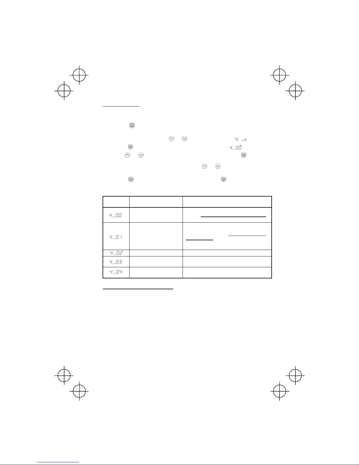
3-24
Basic key operation
Before checking the status of the I/O signals, set function code E52 to "2: Full-menu mode."
(1) When the inverter is powered on, it automatically enters Running mode. In Running mode,
press the
key to enter Programming mode. The menu for function selection will be
displayed.
(2) With the menu displayed, use the
and keys to select "I/O check" ( ).
(3) Press the
key to display the codes for the I/O check item list. (e.g. 0)
(4) Use the
and keys to select the desired I/O check item, then press the key.
The corresponding I/O check data will appear. For control I/O signal terminal and control circuit
terminal input under communication control, use the
and keys to select one of the two
different display methods.
(5) Press the
key to return to the I/O check item list. Press the key again to return to the
menu.
Table 3.15 I/O Check Items
LED monitor
shows:
Contents Description
I/O signals on the control
circuit terminals
Shows the ON/OFF state of the digital I/O terminals.
Refer to "
Displaying control I/O signal terminals"
below for details on the display contents.
I/O signals on the control
circuit terminals under
communication control
Shows the ON/OFF state for the digital I/O terminals
that received a command via RS485
communications. Refer to "
Displaying control I/O
signal terminals" and “Displaying control I/O signal
terminals under communication control” below for
details of the item displayed.
Input voltage on terminal [12] Shows the input voltage on terminal [12] in volts (V).
Input current on terminal [C1] Shows the input current on terminal [C1] in
milliamperes (mA).
Output voltage to analog
meters [FMA]
Shows the output voltage on terminal [FMA] in volts
(V).
Displaying control I/O signal terminals
The status of control I/O signal terminal status may be displayed with ON/OFF of the LED segment
or in hexadecimal display.
■ Display I/O signal status with ON/OFF of the LED Segment
As shown in Table 3.16 and the figure below, each of the segments "a" to "e" on LED1 lights when
the corresponding digital input terminal ([FWD], [REV], [X1], [X2], or [X3]) is short-circuited with
terminal [CM] or terminal [PLC]*, and does not light when it is open. Segment "a" on LED3 lights
when the circuit between output terminal [Y1] and terminal [Y1E] is closed and does not light when
the circuit is open. Segment "a" on LED4 is for te rminal [30ABC]. Segment "a" on LED4 lights when
the circuit between terminals [30C] and [30A] is short-circuited (ON) and does not light when it is
open.
* Terminal [CM] if the jumper switch is set for SINK; terminal [PLC] if the jumper switch is set for
SOURCE.

3-25
• If all terminal input signals are OFF (open), segment "g" on all of LEDs 1 to 4 will blink
("––––").
• Refer to Chapter 5 "FUNCTION CODES" for details.
Table 3.16 Segment Display for External Signal Information
Segment LED4 LED3 LED2 LED1
a 30ABC Y1-Y1E —
FWD-CM or
FWD-PLC *2
b — — —
REV-CM or
REV-PLC *2
c — — —
X1-CM or
X1-PLC *2
d — — —
X2-CM or
X2-PLC *2
e — — —
X3-CM or
X3-PLC *2
f — — (XF)*1 —
g — — (XR)*1 —
dp — — (RST)*1 —
—: No corresponding control circuit terminal exists.
*1 (XF), (XR), and (RST) are assigned for communication. Refer to "
Displaying control I/O signal
terminals under communication control" on the next page.
*2 Terminal [CM] if the jumper switch is set for a sink; terminal [PLC] if the jumper switch is set for a source.
■ Displaying I/O signal status in hexadecimal format
Each I/O terminal is assigned to bit 15 through bit 0 as shown in Table 3.17. An unassigned bit is
interpreted as "0." Allocated bit data is displayed on the LED monitor in 4 hexadecimal digits ("0" to
"F" each).
With the V6, digital input terminals [FWD] and [REV] are assigned to bit 0 and bit 1, respectively.
Terminals [X1] through [X3] are assigned to bits 2 through 4. The bit is set to "1" when the
corresponding input terminal is short-circuited with terminal [CM] or terminal [PLC ] *, and is set to "0 "
when it is open. For example, when [FWD] and [X1] are on ( short-circuited) and all the oth ers are of f
(open), "0005" is displayed on LED4 to LED1.
* Terminal [CM] if the jumper switch is set for a sink; terminal [PLC] if the jumper switch is set for a
source.
Digital output terminal [Y1] is assigned to bit 0. Bit 0 i s set to "1" w hen this ter minal is short- cir cuite d
with [Y1E], and to "0" when it is open. The status of the relay contact output terminal [30ABC] is
assigned to bit 8. It is set to "1" when the circuit between output terminals [30A] and [30C] is closed
and to "0" when the circuit between [30B] and [30C] i s closed. For ex ample, if [Y1] is on a nd [30A] is
connected to [30C], then "0101" is displayed on the LED4 to LED1.
Table 3.17 presents an example of bit assignment and corresponding hexadecimal display on the
7-segment LED.

3-26
Table 3.17 Segment Display for I/O Signal Status in Hexadecimal Format
LED No. LED4 LED3 LED2 LED1
Bit 15 14 13 12 11 10 9 8 7 6 5 4 3 2 1 0
Input
terminal
(RST)*
(XR)* (XF)* - - - - - - - - X3 X2 X1 REV FWD
Output
terminal
- - - - - - -
30AC
- - - - - - - Y1
Binary 0 0 0 0 0 0 0 0 0 0 0 0 0 1 0 1
Example
Hexadecimal
on the
LED
monitor
– : No corresponding control terminal exists.
* (XF), (XR), and (RST) are assigned for communication. Refer to "
Displaying control I/O signal terminals
under communication control
."
Displaying control I/O signal terminals under communication control
During control via communication, input commands sent via RS485 communications cable can be
displayed in two ways: "display with ON/OFF o f the LED segment" and "in hexadecimal format." The
content to be displayed is basically the same as th at for the control I/O signal terminal st atus display ;
however, (XF), (XR), and (RST) are added as inputs. Note that under communications control, I/O
display is in normal logic (using the original signals that are not inverted).

3-27
[ 5 ] Reading Maintenance Information – "Maintenance Information"
Menu #5 "Maintenance information" in Programming mode contains information necessary for
performing maintenance on the inverter. Table 3.18 lists the maintenance information display items
and Figure 3.10 shows the status transition for maintenance information.
* The part in the dotted-line box is applicable only when a remote keypad is set up for operation.
Figure 3.10 "Maintenance Information" Status Transition
Basic key operation
Before viewing maintenance information, set function code E52 to "2" (full-menu mode).
(1) When the inverter is powered on, it automatically enters Running mode. In Running mode,
press the
key to enter Programming mode. The menu for function selection will be
displayed.
(2) With the menu displayed, use the
and keys to select "Maintenance information" ( ).
(3) Press the
key to display the list of maintenance item codes (e.g. ).
(4) Use the
and keys to select the desired maintenance item, then press the key.
The data of the corresponding maintenance item will appear.
(5) Press the
key to return to the list of maintenance items. Press the key again to return to
the menu.

3-28
Table 3.18 Maintenance Display Items
LED Monitor
shows:
Contents Description
Cumulative run
time
Shows the cumulative power-ON time of the inverter.
Unit: thousands of hours.
When the total ON-time is less than 10000 hours (display: 0.001 to
9.999), data is shown in units of one hour. When the total time is
10000 hours or more (display: 10.00 to 65.53), it is shown in units of
10 hours. When the total time exceeds 65535 hours, the displ ay will
be reset to 0 and the count will start again.
DC link circuit
voltage
Shows the DC link circuit voltage of the inverter.
Unit: V (volts)
Max. temperature
of heat sink
Shows the maximum temperature of the heat sink for every hour.
Unit: ºC
Max. effective
current
Shows the maximum effective current for every hour.
Unit: A (amperes)
Capacitance of
the DC bus
capacitor
Shows the current capacitance of the DC bus capacitor, based on the
capacitance when shipping as 100%. Refer to Chapter 7
"MAINTENANCE AND INSPECTION" for details.
Unit: %
Cumulative run
time of
electrolytic
capacitor on the
printed circuit
board
Shows the cumulative run time of the capacitor mounted on the
printed circuit board.
The display method is the same as for "accumulated run time" above.
However, when the total time exceeds 65535 hours, the count stops
and the display remains at 65.53.
Cumulative run
time of the
cooling fan
Shows the cumulative run time of the cooling fan.
The cooling fan ON/OFF control (function code H06) is effective, so
the time when the fan is stopped is not counted.
The display method is the same as for "accumulated run time" above.
However, when the total time exceeds 65535 hours, the count stops
and the display remains at 65.53.
Number of
startups
The cumulative total number of times an inverter run command has
been issued is calculated and displayed.
1.000 indicates 1000 times. When any number ranging from 0.001 to
9.999 is displayed, the display increases by 0.001 per startup, and
when any number from 10.00 to 65.53 is displayed, the display
increases by 0.01 every 10 startups. When the total number exceeds
65535, the display will be reset to 0 and the count will start again.
No. of RS485
errors
Shows the cumulative total number of RS485 communication errors
since first power ON.
Once the number of errors exceeds 9999, the display (count) returns
to 0.
RS485
communications
error content
Shows the latest error that has occurred with RS485 communications
in decimal format.
For the error content, refer to the user's manual for RS485
communication (MEH448).
ROM version of
the inverter
Shows the ROM version of the inverter as a 4-digit display.
ROM version of
the keypad
Shows the ROM version of the keypad panel as a 4-digit display. (For
active remote keypad only.)

3-29
[ 6 ] Reading Alarm Information – "Alarm Information"
Menu #6 "Alarm information" in Programming mode shows, in alarm code, the causes of the past 4
alarms. Further, it is also possible to display alarm information that indica tes the sta tus of the inverter
when the alarm condition occurred. Figure 3.11 shows the status transition of the alarm information
and Table 3.19 lists the details of the alarm information.
Figure 3.11 "Alarm Information" Status Transition

3-30
Basic key operation
Before viewing alarm information, set function code E52 to "2" (full-menu mode).
(1) When the inverter is powered on, it automatically enters Running mode. In Running mode,
press the
key to enter Programming mode. The menu for function selection will be
displayed.
(2) With the menu displayed, use the
and keys to select "Alarm information" ( ).
(3) Press the
key to display the alarm list code (e.g. ).
In the list of alarm codes, the alarm information fo r the last 4 alarms is saved as an alarm history.
(4) Each time the
or key is pressed, the last 4 alarms are displayed in order from the most
recent one as "
", " ", " " and " ."
(5) While the alarm code is displayed, press the
key to have the corresponding alarm item
number (e.g. ) and data (e.g. Output frequency) displayed alternately in intervals of
approximately 1 second. You can also have the item number (e.g. ) and data (e.g.
Output current) for any other item displayed using the
and keys.
(6) Press the
key to return to the alarm list. Press the key again to return to the menu.
Table 3.19 Alarm Information Displayed
LED monitor
shows:
(item No.)
Contents Description
Output frequency Output frequency before slip compensation
Output current Output current
Output voltage Output voltage
Set frequency Set frequency
Running direction
This shows the running direction being output.
F: normal; R: reverse; – – – –: stop
Running status
This shows the running status in hexadecimal. Refer to
Displaying running status in [3] "Monitoring the Running
Status."
Cumulative running
time
Shows the cumulative power-ON time of the inverter.
Unit: thousands of hours.
When the total ON-time is less than 10000 hours (display:
0.001 to 9.999), data is shown in units of one hour. When the
total time is 10000 hours or more (display: 10.00 to 65.53), it is
shown in units of 10 hours. When the total time exceeds 65535
hours, the display will be reset to 0 and the count will start
again.
No. of startups
The cumulative total number of times an inverter run command
has been issued is calculated and displayed.
1.000 indicates 1000 times. When any number ranging from
0.001 to 9.999 is displayed, the display increases by 0.001 per
startup, and when any number from 10.00 to 65.53 is displayed,
the display increases by 0.01 every 10 startups. When the total
number exceeds 65535, the display will be reset to 0 and the
count will start again.

3-31
DC link circuit voltage
Shows the DC link circuit voltage of the inverter's main circuit.
Unit: V (volts)

3-32
Table 3.19 Continued
LED monitor
shows:
(item No.)
Contents Description
Max. temperature of
heat sink
Shows the temperature of the heat sink.
Unit: ºC
Terminal I/O signal
status (displayed
with the ON/OFF of
LED segments)
Signal input terminal
status (in hexadecimal format)
Terminal output
signal status (in
hexadecimal format)
Shows the ON/OFF status of the digital I/O terminals. Refer to
"
Displaying control I/O signal terminals" in [4] "Checking I/O
Signal Status" for details.
No. of consecutive
occurrences
This is the number of times the same alarm occurs
consecutively.
Overlapping alarm 1
Simultaneously occurring alarm codes (1)
(– – – – is displayed if no alarms have occurred.)
Overlapping alarm 2
Simultaneously occurring alarm codes (2)
(– – – – is displayed if no alarms have occurred.)
Terminal I/O signal
status under
communication control
(displayed with the
ON/OFF of LED
segments)
Terminal input signal
status under
communication control
(in hexadecimal
format)
Terminal output signal
status under
communication control
(in hexadecimal
format)
Shows the ON/OFF status of the digital I/O terminals under
communication control. Refer to "
Displaying control I/O
signal terminals under communication control" in [4]
"Checking I/O Signal Status" for details.
When the same alarm occurs a number of times in succession, the alarm information fo
r
the first occurrence is retained and the information for the subsequent occurrences is
discarded. Only the number of consecutive occurrences will be updated.

3-33
3.2.3 Alarm mode
When an abnormal condition occurs, the protective function is invoked to issue an alarm, and the
inverter automatically enters Alarm mode. At the same time, an alarm code appears on the LED
monitor.
Releasing the Alarm and Transferring the Inverter to Running Mode
Remove the cause of the alarm and press the
key to release the alarm and return to Running
mode. The alarm can be removed using the
key only when the alarm code is displayed.
Displaying the Alarm History
It is possible to display the most recent 3 alarm codes in addition to the one currently displayed.
Previous alarm codes can be displayed by pressing the
or key while the current alarm code is
displayed.
Displaying the Status of Inverter at the time of Alarm
If an alarm occurs, you may check various running status information (output frequency and output
current, etc.) by pressing the
key when the alarm code is displayed. The item number and data
for each running information is displayed in alternation.
Further, you can view various pieces of information on the status of the inverter using the
or
key. The information displayed is the same as for Menu #6 "Alarm information" in Programming
mode. Refer to Table 3.19 in 3.2.2 [6] "Reading Alarm In formation."
Pressing the
key while the status information is display ed returns the di splay to the alarm codes.
When the status information is displayed af ter removal of th e alarm cause , pressing the
key twice will take you backt o the display of the alarm code, and then the inverter will be
released from the alarm state. If a run command ha s been receiv ed by thi s tim e, the mo to
r
will start running.
Transit to Programming Mode
Y ou can also go ba ck to Programming mode by pressing the
+ keys simultaneously while the
alarm is displayed, and modify the setting of function codes.
Figure 3.12 summarizes the possible transitions between different menu items.

3-34
Figure 3.12 Alarm Mode Status Transition

4-1
Chapter 4 RUNNING THE MOTOR
4.1 Running the Motor for a Test
4.1.1 Inspection and preparation prior to the operation
Check the following prior to starting the operation.
(1) Check if connection is correct.
Especially check if the power wires are connected to inverter output terminals U, V and W and
that the grounding wire is connected to the ground electrode correctly.
• Do not connect power supply wires to the inverter output terminals U, V, and W. Otherwise, the
inverter may be broken if you turn the power on.
• Be sure to connect the grounding wires of the inv erter and the motor to the gro und ele ctrode s.
Otherwise, electric shock may occur.
(2) Check for short circuits between terminals
and exposed live parts and ground faults.
(3) Check for loose terminals, connectors and
screws.
(4) Check if the motor is separated from
mechanical equipment.
(5) Turn the switches off so that the inverter does
not start or operate erroneously at power-on.
(6) Check if safety measures are taken against
runaway of the system, e.g., a defense to
protect people from unexpectedly
approaching your power system.
<for 3-phase power supply>
Figure 4.1 Connection of Main Circuit Terminals
(Three-phase power supply)
4.1.2 Turning on power and checking
• Be sure to install the covers for both the main circuit terminal block and control circuit terminal
block before turning the power on.
Do not remove the cover during power application.
• Do not operate switches with wet hands.
Otherwise electric shock could occur.
Turn the power on and check the following points. This
is a case when no function code data is changed from
the factory setting.
(1) Check if the LED monitor displays "0.00" (means
that the set frequency is 0 Hz) that is blinking. (See
Figure 4.2.)
If the LED monitor display s numbers except "0 .00,"
then rotate the potentiometer to set "0.00" as the
set frequency.
(2) Check if a built-in cooling fan rotates (for models
with 1.5 kW or more).
Figure 4.2 Display of the LED Monitor
after Power-on

4-2
4.1.3 Preparation before running the motor for a test--Setting function code data
Before starting runni ng th e motor, set functi on code da ta speci fied i n Table 4.1 to the motor ratings
and your system design values. For the motor, check the rated values printed on the nameplate of
the motor. For your system design values, ask system designers about them.
For details about how to change function code data, refer to Chapter 3, Section 3.2.2
"Programming mode [1] Setting the Function Codes." If the motor cap acity is dif ferent from the
inverter capacity, refer to Chapter 5, function code H03.
Table 4.1 Settings of Function Code Data before Driving the Motor for a Test
Function code Name Function code data Factory setting
Base frequency 60.0 (Hz)
Rated Voltage (at base
frequency)
0 (V)
(Output voltage interlocked
with the source voltage)
Motor Parameter
(Rated capacity)
Applicable motor rated
capacity
Motor Parameter
(Rated current)
Rated current of applicable
motor
Motor Selection
Motor ratings (printed on the
nameplate of the motor)
0: Characteristic of motor, 0
Maximum frequency 60.0 (Hz)
Acceleration time 1* 6.00 (s)
Deceleration time 1*
System design values
* For a test-driving of the motor,
increase values so that they
are longer than your system
design values. If the set time is
short, the inverter may not
start running the motor.
6.00 (s)
4-3
4.1.4 Test run
If the user set the function codes wrongly or without completely understanding this Instruction
Manual, the motor may rotate with a torque or at a speed not permitted for the machine.
Accident or injury may result.
Follow the descriptions of the previous Section 4.1.1, "Inspection and Preparation prior to the
Operation" to Section 4.1.3, "Preparation before running the motor for a test," and begin test-driving
of the motor.
If any abnormality is found to the inverte r or motor , immediately stop operation and determine the
cause referring to Chapter 6, "TROUBLESHOOTING."
------------------------------------------------ Procedure for Test Run ------------------------------------------------
(1) Turn the pow er on and check that the LED monito r blinks while indica ting the 0.00 Hz frequen cy.
(2) Rotate the built-in potentiometer clockwise, set the frequency to a low frequency such as 5 Hz.
(Check that set frequency blinks on the LED monitor.)
(3) Press the
key to start running the motor in the forward direction. (Check that the set
frequency is displayed on the LED monitor correctly.)
(4) To stop the motor, press the
key.
<Check the following points>
• Check if the direction of rotation is correct.
• Check for smooth rotation without motor humming or excessive vibration.
• Check for smooth acceleration and deceleration.
When no abnormality is found, rotate the potentiometer clockwise to raise the set frequency. Check
the above points for the test-driving of the motor.
-----------------------------------------------------------------------------------------------------------------------------------
4.2 Operation
After checking that the operations finished correctly through the above test-driving, start normal
operation.

5-1
Chapter 5 FUNCTION CODES
5.1 Function Code Tables
Function codes enable the V6 series of inverters to be set up to match your system requirements.
Each function code consists of a 3-letter string. The fir st letter is an alphabet that identifies its group
and the following two letters are numerals that identify each individual code in the group. The
function codes are classified into seven groups: Fundamental Functions (F codes)
, Extension
Terminal Functions (E codes), Control Functions of Frequency (C codes), Motor Parameters (P
codes), High Performance Functions (H codes), Application Functions (J codes), and Link Function
(y codes). To determine the property of each function code, set data to the function code.
The following descriptions supplement those given in the function code tables on page 5-3 and
subsequent pages.
Changing, validating, and saving function code data when the motor is running
Function codes are indicated by the following based on whether they can be changed or not when
the inverter is running:
Notation Change when running Validating and saving function code data
Y* Possible
If the data of the codes marked with Y* is changed, the change
will immediately take effect; however, the change is not saved
into the inverter's memory. To save the change, press the
key. If you press the
key without pressing the key to exit
the current state, then the changed data will be discarded and
the previous data will take effect for the inverter operation.
Y Possible
The data of the codes marked with Y can be changed with the
and keys regardless of whether the motor is running or
not. Pressing the
key will make the change effective and
save it into the inverter's memory.
N Impossible —
Copying data
Connecting a remote keypad (option) to an inverter via the RS485 communications card (option)
allows copying the data stored in the inverter's memory into the keypad's memory (refer to Menu #7
"Data copying" in Programming mode). With this feature , you can ea sily tran sfer the dat a sav ed in a
source inverter to other destination inverters.
If the specifications of the source and destination inverters dif fer, some code data may not be copied
to ensure safe operation of your power system. Therefore, you need to set up the uncopied code
data individually as necessary. Whether data will be copied or not is detailed with the following
symbols in the "Data copy" column of the function code tables given below.
Y: Will be copied unconditionally.
Y1: Will not be copied if the rated capacity differs from the source inverter.
Y2: Will not be copied if the rated input voltage differs from the source inverter.
N: Will not be copied. (The function code marked "N" is not subject to the Verify operation, either.)
It is recommended that you set up those function codes w hich are not subje ct to th e Copy opera tion
individually using Menu #1 "Data setting" as necessary.

5-2
Using negative logic for programmable I/O terminals
The negative logic signaling system can be used for the digital input and output terminals by setting
the function codes specifying the properties for those terminals. Negative logic refers to inverted
ON/OFF (logical value 1 (true)/0 (false)) state of input or output signal. An ON-active signal (the
function takes effect if the terminal is short-circuited.) in the normal logic system is functionally
equivalent to OFF-active signal (the function takes effect if the terminal is opened.) in the negative
logic system.
To set the negative logic system for an I/O signal terminal, display data of 1000s (by adding 1000 to
the data for the normal logic) in the corresponding function code and then press the
key.
For example, if a coast-to-stop command (BX: data = 7) is assigned to any one of digital input
terminals [X1] to [X3] by setting any of function codes E01 through E03, then turning (BX) on will
make the motor coast to a stop. Similarly, if the coast-to-stop command (BX: data = 1007) is
assigned, turning (BX) off will make the motor coast to a stop.
Restriction on data displayed on the LED monitor
Only four digits can be displayed on the 4-digit LED monitor. If you enter more than 4 digits of data
valid for a function code, any digits after the 4th digit of the set data will not be displayed, however
they will be processed correctly.
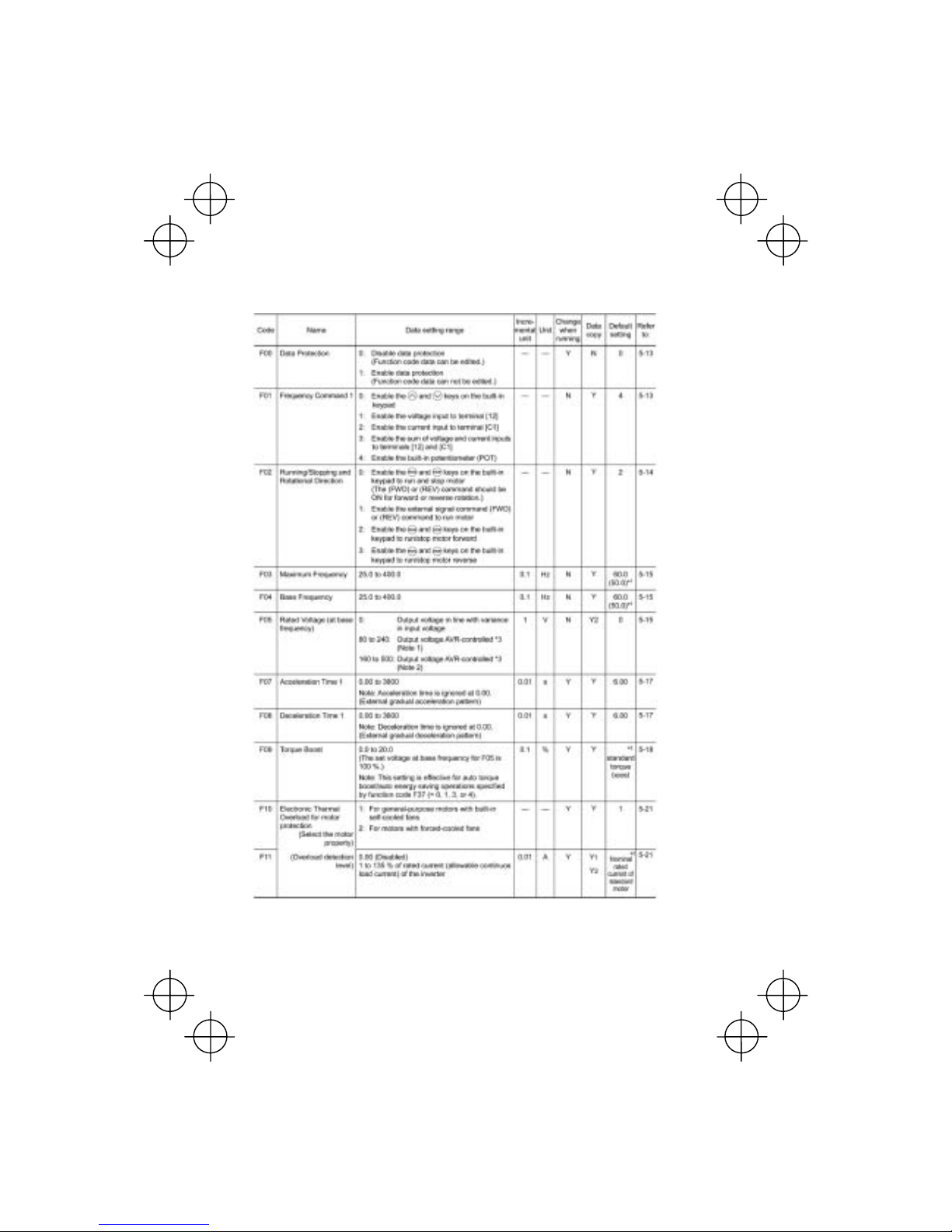
5-3
The following tables list the function codes available for the V6 series of inverters.
F codes: Fundamental Functions
*1 Values in parentheses ( ) in the above table denote default settings for the EU version except three-phase 200 V
se-ries of inverters.
*2 "Standard torque boost," "Nominal rated current of standard motor," and "Nominal rated capacity of standard motor"
differ depending upon the rated capacity. Refer to Table 5.1 "Standard Motor Parameters" on page 5-12.
*3 AVR: Automatic Voltage Regulat or
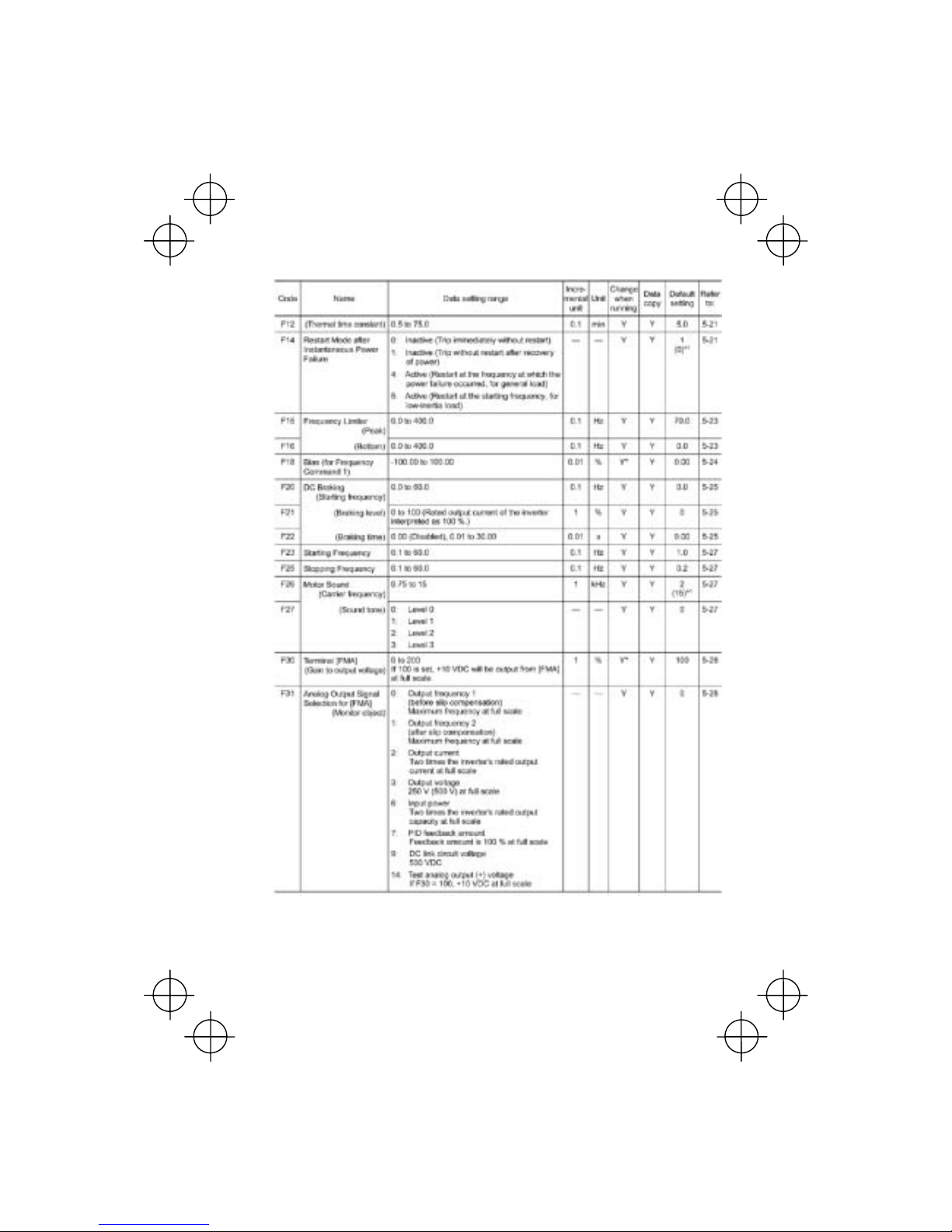
5-4

5-5
(Note) The default setting of function code F50 is 999 forless than0.75kW standard models, and 0 for braking resistor
built-in type, more than 1.5kW models.
E codes: Extension Terminal Functions

5-6
(Note) Function codes E45 to E47 appear on the LED monitor; however, the V6 series of inverters does not recognize these codes.
*1 Values in parentheses ( ) in the above table denote default settings for the EU version.
*2 "Standard torque boost," "Nominal rated current of standard motor," and "Nominal rated capacity of standard motor"
differ depending upon the rated input voltage and rated capacity. Refer to Table 5.1 “Standard Motor Parameters" on
page 5-12.

5-7

5-8
C codes: Control Functions of Frequency

5-9
P codes: Motor Parameters
H codes: High Performance Functions
* "Standard torque boost," "Nominal rated current of standard motor," and "Nominal rated capacity of standard motor"
differ depending upon the rated input voltage and rated capacity. Refer to Table 5.1 "Standard Motor Parameters".

5-10
(Note 1) Function code H71 appears on the LED monitor; however, the V6 series of inverters does not recognize this
code.
(Note 2) Function code H95 is valid on the inverters with ROM versions of C1S11000 or higher. (The lowest four digits of
the ROM version can be displayed on the LED monitor. For details, refer to 3.2.2 [5] "Reading Maintenance
Information" in Chapter 3.
* Value in p arentheses ( ) i n the H95 de fault setting column denotes the setting for the EU v ersion. If initialized by H03, the
H95 will be set to 0.

5-11
J codes: Application Functions
y codes: Link Functions
* The table below lists the factory settings of "Standard torque boost," "Nominal rated current of
standard motor," an d "Nominal rated ca p acity of st an dard motor" in the "Default setting " column of
the above tables.

5-12
Table 5.1 Standard Motor Parameters
Standard
torque
boost (%)
Nominal rated current of
standard motor (A)
Nominal rated
capacity of
standard motor
(kW)
Function codes
F11, E34 and P03
Shipping destination (version)
Power
supply
voltage
Applicable
motor
rating
(kW)
Inverter type
Function code
F09
Asia EU Japan
Function code
P02
0.1 V6 – 01 – 4 8.4 0.62 0.68 0.61 0.1
0.2 V6 – 02 – 4 8.4 1.18 1.30 1.16 0.2
0.4 V6 – 04 – 4 7.1 2.10 2.30 2.13 0.4
0.75 V6 – 07 – 4 6.8 3.29 3.60 3.36 0.75
1.5 V6 – 15 – 3 6.8 5.55 6.10 5.87 1.5
2.2 V6 – 22 – 3 6.8 8.39 9.20 8.80 2.2
Three-
phase
200 V
3.7 V6 – 37 – 3 5.5 13.67 15.00 14.38 3.7

5-13
5.2 Overview of Function Codes
This section provides an overview of the function codes frequently used for th e V6 series of inv erter.
F00 Data Protection
Specifies whether function code data is to be protected from being accidentally
changed by keypad operation. If data prote ction is enabled (F00 = 1),
or key
operation to change data is disabled so that no function code dat a, except F00 dat a,
can be changed from the keypad. To change F00 data, simultaneous keying of
+
keys is required.
F01, C30 Frequency Command 1 and 2
Selects the devices to set the set frequency for driving the motor.
Set F01 to: To do this
0 Enable the and keys on the built-in keypad. (Refer to
Chapter 3 "OPERATION USING THE KEYPAD.")
1 Enable the voltage input to terminal [12] (0 to +10 VDC, maximum
frequency obtained at +10 VDC).
2 Enable the current input to terminal [C1] (+4 to +20 mA DC,
maximum frequency obtained at +20 mA DC).
3 Enable the sum of volt age and current inputs to terminals [12] and
[C1]. See the two items listed above for the setting range and
maximum frequencies.
Note: If the sum exceeds the maximum frequency, the maximum
frequency will apply.
4 Enable the built-in potentiometer (POT). (Maximum frequency
obtained at full scale of the POT)
• For frequency commands by terminals [12] (voltage) and [C1]
(current) and by the built-in potentiometer, setting the gain and bias
changes the relationship between those fre quency commands and the
drive frequency to enable matching your system requirements. Refe
r
to function code F18 for details.
• For the inputs to terminals [12] (voltage) and [C1] (current), low-pass
filters can be enabled. Refer to the FUNCTION CODES “C33” and
“C38” for details.
In addition to "F01 Frequency set 1," "C30: Frequency se t 2" is available. To switch
between them, use the terminal command (Hz2/Hz1). For details of the (Hz2/Hz1),
refer to "E01 to E03, E98, and E99: Command Assignment to Terminals [X1] to [X3],
[FWD], and [REV]."

5-14
F02 Running/Stopping and Rotational Direction
Selects a source issuing a run command--keypad or external control signal input.
- If F02 = 0, 2, or 3, the inverter can run the motor by the
and
keys on the
built-in keypad. The motor rotational direction can be specified in two ways,
either by control signal input (F02 = 0) or by use of prefixed forward or reverse
rotation (F02 = 2 or 3).
When F02 = 0, to specify the motor rotational direction by control signal input,
assign the commands (FWD) and (REV) to terminals [FWD] and [REV],
respectively. Turn on the (FWD) or (REV) for the forward or reverse direction,
respectively, and then press the
key to run the motor.
- If F02 = 1, the inverter can run the motor by control signal inputs. To specify the
motor rotational direction, assign the commands (FWD) and (REV) to terminals
[FWD] and [REV], respectively. Turn on the (FWD) or (REV) for the forward or
reverse direction, respectively. If both of (FWD) and (REV) are turned on
simultaneously, the inverter immediately decelerates to stop the motor.
The table below lists the operational relationship between function code F02
(Running/Stopping and Rotational Direction), the
and key operation, and
control signal inputs to terminals [FWD] and [REV ], w hich determine s the r ot a tional
direction.
Control signal inputs to
terminals [FWD] and [REV]
Function
code F02:
Key on the
keypad
Function code E98
(FWD) command
Function code E99
(REV) command
Motor
rotational
direction
OFF OFF Stop
ON OFF Forward
OFF ON Reverse
key
ON ON Stop
OFF OFF
ON OFF
OFF ON
0
key
ON ON
Stop
OFF OFF Stop
ON OFF Forward
OFF ON Reverse
1 Ignored.
ON ON Stop
key
Forward
2 (forward/
fixed)
key
Ignored.
Stop
key
Reverse
3
(reverse/
fixed)
key
Ignored.
Stop

5-15
• If you have assigned the (FWD) or (REV) function to the [FWD] or
[REV] terminal, you cannot change the setting of function code F02
while the terminals [FWD] and [C M ]* or the te rminal s [REV ] and [CM ]*
are short-circuited.
• If you have specified the external signal (F02=1) as the running
command and have assigned functions other than the (F WD) or (REV)
function to the [FWD] or [REV] terminal, caution should be exercised in
changing the settings. Because, if under this condition you assign the
(FWD) or (REV) function to the [FWD] or [REV] terminal while the
terminals [FWD] and [CM]* or the terminals [REV] and [CM]* are
short-circuited, the motor would start running.
*[CM] replaces with [PLC] for SOURCE mode.
F03 Maximum Frequency
Sets the maximum frequency to drive the motor. Setting the frequency out of the
range rated for the equipment driven by the inverter may cause damage or a
dangerous situation. Set a maximum frequency appropriate for the equipment. For
high-speed motors, it is recommended that the carrier frequency be set to 15 kHz.
The inverter can easily set high-speed operation. When chang ing the speed setting ,
carefully check the specifications of motors or equipment beforehand.
Otherwise injuries could occur.
If you modify the data of F03 to apply a higher drive frequency,
concurrently change the data of F15 for a peak frequency limiter suitable
to the drive frequency.
F04
F05
H50
H51
Base Frequency
Rated Voltage (at Base Frequency)
Non-linear V/f Pattern (Frequency)
Non-linear V/f Pattern (Voltage)
These function codes set the base frequency and the v oltage a t the ba se frequ ency
essentially required for running the motor properly. If combined with the related
function codes H50 and H51, these function codes may set data needed to drive the
motor along the non-linear V/f pattern.
The following description includes setting-up required for the non-linear V/f pattern.
Base frequency (F04)
Set the rated frequency printed on the nameplate located on the motor.
Rated voltage (at base frequency) (F05)
Set 0 or the rated voltage printed on the nameplate labeled on the motor.
- If 0 is set, the inverter supplies voltage equivalent to that of the power source of
the inverter at the base frequency. In this case, the output voltage will vary in line
with any variance in input voltage.
- If the data is set to anything othe r than 0, the inverter au tomatically keeps the
output voltage constant in line with the setting. When any of the automatic torque
boost settings, automatic energy saving or slip compensation is active, the
voltage settings should be equal to the rating of the motor.

5-16
If F05 is set to match the rated voltage of the motor, motor efficiency will
be better than that it is set to 0. Therefore, when brakes are applied to the
motor, energy loss decreases and the motor regenerates larger braking
energy, which can easily cause the overvoltage protection function (
OUn
where n=1 to 3) to be activated. Note that the allowable power
consumption capacity of the inverter for braking energy is limited by the
specifications. If the overvoltage protection function is activated, it may be
necessary to increase deceleration time or use an external braking
resistor.
Non-linear V/f pattern for frequency (H50)
Sets the non-linear V/f pattern for frequency component.
(Setting 0.0 to H50 disables the non-linear V/f pattern operation.)
Non-linear V/f pattern for voltage (H51)
Sets the non-linear V/f pattern for voltage component.
If the rated voltage at base frequency (F05) is set to 0, the data settings of function
codes H50 and H51 will be ignored.
If you set the data of H50 to 25 Hz or lower (Operation under low base
frequency), the inverter output voltage may be limited.
Defining non-linear V/f patterns (F04, F05, H50 and H51)
Function codes F04 and F05 define a non-linear V/f pattern that forms the
relationship between the inverter's output frequency and voltage.
Furthermore, setting the non-linear V/f pattern using function codes H50 and H51
allows patterns with higher or lower voltage than that of the normal pattern to be
defined at an arbitrary point inside or outside the base frequency. Generally, when a
motor is driven at a high speed, its internal impedance may increase and output
torque may decrease due to the decreased drive voltage. This feature helps you
solve that problem. Note that setting the voltage in excess of the inverter’s input
source voltage is not allowed.
Normal (linear) V/f pattern
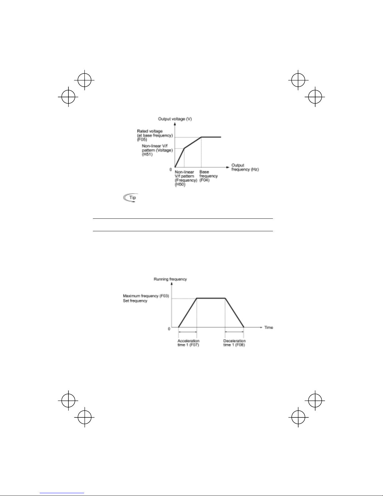
5-17
V/f pattern with single non-linear point inside the base frequency
You can also set the optional non-linear V/f range (H50: Frequency) for
frequencies exceeding the base frequency (F40).
F07
F08
Acceleration Time 1, Deceleration Tim e 1
The acceleration time specifies the length of time the frequency increa ses from 0 Hz
to the maximum frequency. The deceleration time specifies the length of time the
frequency decreases from the maximum frequency down to 0 Hz.
In case the set frequency is equal to the maximum frequency (F03)
The actual acceleration and deceleration times are the same as the specified
acceleration time and deceleration time.

5-18
In case the set frequency is lower than the maximum frequency (F03)
The actual acceleration and deceleration times are shorter than the specified
acceleration time and deceleration time.
• If you choose S-curved acceleration/deceleration or curvilinear
acceleration/deceleration in "curvilinear acceleration/deceleration"
(H07), the actual acceleration/deceleration times are longer than the
specified times.
• If you specify an improperly short acceleration/deceleration time, then
the current limiting function or the automatic deceleration function ma
y
activated, resulting in an actual acceleration/deceleration time longe
r
than the specified one.
F09
F37
Torque Boost
Load Selection/Auto Torque Boost/Auto Energy Saving Operation
In general, there are two different propertie s of loads--the v ariable torque loud (fans
and pumps) and the constant torque load (industrial machinery). You can select a
V/f pattern optimized to the load property.

5-19
Manual torque boost
In manual torque boost mode, the inverter maintains the output at a constant level
regardless of the load. When you use this mode, select the appropriate V/f pattern
(variable torque or constant torque characteristics) with Load Selection (F37). To
keep the motor starting torque, manually select optimal inverter output voltage for
the motor and load by setting an optimal torque boost rate to F09 in accordance with
the motor and its load.
Setting an excessive torque boost rate may result i n over-excitation an d overheat of
the motor during light or no load operation.
Manual torque boost keeps the output voltage constant even if the load varies,
assuring stable motor operation.
Variable torque characteristics (F37 = 0)
Constant torque characteristics (F37 = 1)
• Set an appropriate torque boost rate that will keep the starting torque
of the motor within the voltage level in the low frequency zone. Setting
an excessive torque boost rate may result in over-excitation o
r
overheat of the motor during no load operation.
• The F09 data setting is effective when F37 (Load Selection/Auto
Torque Boost/Auto Energy Saving Operation) is set to 0, 1, 3, or 4.
Automatic torque boost
This feature automatically optimizes the output voltage to fit the motor and its load.
Under a light load, it decreases the output voltage to prevent the motor from
over-excitation; under a heavy load, it increases the output voltage to increase
torque.
Since this feature is related to the motor properties, it is necessary to set the rated
voltage at base frequency (F05) and motor parameters (P codes) properly.
For the automatic torque boost feature, which is related to the moto
r
characteristics, you need to consistently set the voltage at the base
frequency (F05) and motor parameters P02, P03 and P99 appropriately
for the motor rating and characteristics.
Auto energy saving operation
This feature controls the terminal volt age of the motor au tomatically to minimize the
motor power loss. (Note that this feature may not be effective depending upon the
motor characteristics. Check the characteristics before using this feature.)
The inverter enables this feature for constant speed operation only. During
acceleration and deceleration, the inverter will run w ith manual or automatic torque
boost, depending on function code F37. If auto energy saving opera tion i s ena bled,
the response to a change in motor speed may be slow. Do not use this feature for a
system that requires quick acceleration and deceleration.

5-20
Use auto-energy saving only where the base frequ ency is 60 Hz or lower.
If the base frequency is higher than 60 Hz, then you may get little or no
energy saving effect.
The auto energy saving operation is designed for use with the frequency
lower than the base frequency. If the frequency becomes higher than the
base frequency, the auto energy saving operation will be invalid.
For the auto energy saving function, which is related to the moto
r
characteristics, you need to consistently set the voltage at the base
frequency (F05) and motor parameters P02, P03 and P99 appropriately
for the motor rating and characteristics.
Given below are examples of proper setting in combination with F09 and F37.
If you do not select auto energy saving operation
Load type To select manual torque
boost, set:
To select automatic torque
boost, set:
Variable torque
F37 = 0
F09 = 0.0 to 20.0 (%)
Constant torque
F37 = 1
F09 = 0.0 to 20.0 (%)
F37 = 2
If you select auto energy saving operation
Load type To select manual torque
boost, set:
To select automatic torque
boost, set:
Variable torque
F37 = 3
F09 = 0.0 to 20.0 (%)
Constant torque
F37 = 4
F09 = 0.0 to 20.0 (%)
F37 = 5

5-21
F10 to F12
Electronic Thermal Simulation for protection of motor
(Select the motor characteristics, overload detection level, and Thermal time
constant)
F10 through F12 set the thermal characteristics of the motor for electronic thermal
simulation, which is used to detect overload conditions of the motor. More
specifically, F10 specifies the motor characteristics, F12 the thermal time constant,
and F11 the overload detection level.
Thermal characteristics of the motor specified by these function codes are
also used for the overload early warning. Therefore, ev en if you ne ed only
the overload early warning, set these characteristics data to function
codes F10 and F12.
F10 selects the cooling characteristics of the motor--built- in cooling fan or externally
powered forced-ventilation fan.
Set F10 to: If the motor is cooled by:
1 Built-in cooling fan for general-purpose motors (self-cooled)
(The cooling performance will decrease with low frequency
operations.)
2 Forced-ventilation fan powered by an inverter-driven motor or
high-speed motor
(The cooling performance will be kept constant regardless of the output
frequency.)
F11 specifies the le vel at which an ov erload condition is to be recognized. Or dinarily,
set F11 to 1.0 to 1.1 times the allowable continuous current (rated current of the
motor (P03)) at the rated drive frequency (base frequency) of the motor. To disable
the electronic thermal function, set F11 to 0.00 (no effect).
F12 sets the thermal time constant of the motor. The inverter interprets the time
constant as an operation period of the electronic thermal function. During the
specified operation period, the inverter will activ ate the electronic th ermal function i f
150% current of the operation level specified by F11 flows continuously. The time
constant of other induction motors is set to approximately 5 minutes by factory
default.
Data entry range: 0.5 to 75.0 (minutes, in 0.1-minute increment)
F14 Restart Mode after Instantaneous Power Failure
Selects the action of the inverter to be followed when an instantaneous power
failure occurs.
If the inverter detects that the DC link circuit voltage has dropped to less than the
specified undervoltage limit during operation, it interprets the state as an
occurrence of an instantaneous power failure. However, if the inverter runs with a
light load connected to the motor and the period of the power failure is too short,
then it may not detect the power failure and continue to run.

5-22
- Trip immediately (F14 = 0)
If an instantaneous power failure occurs when the inverter is in Running mode so
that the inverter detects undervoltage of the DC link circuit, then the inverter
immediately stops its output and displays the undervoltage alarm "
LU " on the LED
monitor. The motor w ill coast to a stop and the inv erter will no t rest art automatically.
- Trip after recovery of power (F14 = 1)
If an instantaneous power failure occurs when the inverter is in Running mode,
causing the inverter to detect undervoltage of the DC link circuit, the inverter
immediately stops its output without transferring to Alarm mode or displaying the
undervoltage alarm "
LU ". The motor will coast to a stop. When the power is
recovered, the inverter will enter Alarm mode for undervoltage with displaying the
alarm "
LU ". The motor will be still coasting.
- Restart at the frequency at which the power failure occurred (F14 = 4)
If an instantaneous power failure occurs when the inverter is in Running mode so
that the inverter detects undervoltage of the DC link circuit, then the inverter saves
the current output frequency and stops its output to make the motor to coast to a
stop. When the power is recovered with any run command being on , the inverter will
restart at the saved frequency.
During the instantaneous power failure, if the motor speed slows down, the current
limiter function of the inverter will be activated and automatically lower the output
frequency. Upon synchronization of the output frequency and motor speed, the
inverter accelerates up to the previous output frequency. Refer to the figure (F14 =
4) given below for details.
To synchronize the output frequency and motor speed, however, the momentary
overcurrent limiter (H12 = 1) should be enabled.
This setting is optimal for operations in which the motor speed rarely slows down
due to the heavy moment of inertia of its load even if the motor coasts to a stop
because of the instantaneous power failure.
- Restart at the starting frequency (F14 = 5)
If an instantaneous power failure occurs when the inverter is in Running mode so
that the inverter detects undervoltage of the DC link circuit, then the inverter
immediately stops its output. After the power is recovered, entry of any run
command will restart the inverter at the frequency specified by function code F23.
 Loading...