

TRS-ETA-005-01 /MD-000074158A
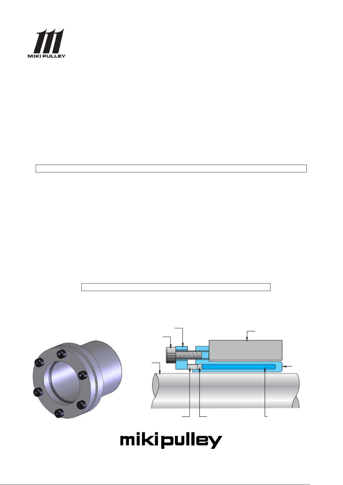
Shaft
Clamping bolt
Hub
Piston ring
Sleeve
Flange
Sealing ring
Pressure medium
P1
P2
P4
P8
ETP BUSH
ETP-CLASSIC
ETP-A/ETP-A-B/ETP-A-C
ETP-A-S/ETP-A-R
Instruction Manual
Before use this product, read the instruction manual carefully and use the product safety and correctly.
1.Before using・・・・・・・・・・・・・・・
2.Safety Precautions・・・・・・・・・・・・
3.Installation procedure ・・・・・・・・・・
4.Removal ・・・・・・・・・・・・・・・・・
1.Before using
1-1 After opening the package
First, please check the following points.
1) Is the product what you ordered?
2) Is the product damaged during transportation?
If any problems are found, please contact your supplier.
1-2 Structure and Parts
-1-
DANGER
When death or serious injury may result
by mishandling
CAUTION
When disability or only physical damage
may result by mishandling
Structural precautions
Touching the product during operation could cause injury. Place a safety
cover to avoid any accident. Additionally, set up a safety mechanism for
quick stop of the product when opening the cover.
Do not use the product near flammable liquids or in the presence of gas
and other explosive air particles.
The driven and driving sides could be completely detached when the
product is damaged. Set up a safety mechanism such as a safety brake to
avoid any danger.
Mounting precautions
Depending on the tightening adjustment of bolt or screw, exceptionally
dangerous situations such as product damage or performance degradation
could occur. Always use a calibrated torque wrench and clamp at the
tightening torque specified by Miki Pulley.
It is very dangerous if the driving part starts by accident while mounting
the product. Be sure that the main power of the equipment is turned off.
Cautions during operation
If the product is used in excess of more than its maximum rated
permissible speed, very dangerous product damage could occur by a large
vibration.
Due to the exposed rotor, touching the product during operation may
cause injury. Make sure not to touch the product during operation.
Using the product with more than the "maximum permissible
misalignment" could cause damage or adverse effect on the equipment.
Always operate the product within the specified "maximum permissible
DANGER
2.Safety Precautions
Please read carefully through the instruction manual and the technical information for proper
use and safety. In this manual, safety precautions are classified by "DANGER" and "CAUTION".
Equipment use (atomic energy, aerospace, medical treatment, transportation, or various
safety devices) that may result in serious bodily injury or loss of life directly by mechanical
failure or mishandling, careful examination is necessary. Contact us for further information. The
company has taken all possible measures to produce a quality product; however, continuous
rotational states when the clutch can not be disengaged or coasting of the machine when the
brakes went off is envisioned as emergency. Please pay attention to safety measures in case
anything goes wrong.
-2-
misalignment."
Cautions for maintenance and inspection
It is extremely dangerous if the driving part starts operating by accident
while dismounting the product. Make sure that the main power of the
equipment is off.
Cautions for disposal
Do not leave the product around where young children may play.
Structural precautions
Do not use the product in an environment where chemicals may spill,
humidity is high, or in hot or cold temperature.
Mounting precautions
The installation of the product must be performed within the specified
maximum permissible error. Using the product with more than the
maximum permissible error could cause damage or adverse effect on the
equipment.
Using a bolt or screw that is not specified by our company could damage
the product. Do not use any bolt or screw unspecified.
To avoid any injury by stripping, spring pin or keyway, make sure to wear
protective equipment such as safety glasses or gloves.
Lifting of a heavy weight could cause back injury. Use a hoist when
carrying or mounting the product.
Cautions during operation
Using the product with more than the specified permissible torque could
cause damage or adverse effect on the equipment.
If abnormal noises or vibrations occur during operation, improper
mounting should be considered. Do not leave the situation as it is. It may
cause damage to the equipment itself. Also, for reasons other than above,
the belts and other screws may loosen or become defective even if the
product is mounted correctly.
Using the product when the locking part is in a slip condition could over
heat the product, which could cause damage to the equipment.
Cautions for maintenance and inspection
We will refuse to take responsibility as to the damaged product that is
dismantled, remodeled or repaired by a third party except our company and
the designated company. Therefore, for the product that the assembly
process or procedure of dismantlement is described in the manual, we will
not be responsible as well. Please use our service network for repair and
dismantlement.
Cautions for disposal
Call for a waste-control-collection company for disposal.
CAUTION
-3-

3.Installation procedure
①
②
③
④
3-1 Cleaning the shaft and hub
Wipe off any rust, dust and oil contents adhering to the surface of the shaft and hub with cloth. If
any grease is attached, remove the grease completely. Meanwhile, the oil content attached on the
surface of the ETP-CLASSIC should be also removed.
(Notice)
Do not use molybdenum-containing oil. It will affect a change in the coefficient of friction.
3-2 Mounting on the shaft and hub
Place the ETP-CLASSIC by the hub and mount in the shaft. If a correct positioning for the shaft and
hub is necessary, adjust their positions before fastening the pressure screw.
(Notice)
Do not fasten the pressure screw until the ETP-CLASSIC is completely set to the shaft and hub.
3-3 Fastening the clamping bolt
Put a hand over the ETP-CLASSIC and fasten the clamping bolt half-turn each in the order of ①
② ③ ④ as below. Using a torque wrench, fasten the ETP-CLASSIC with a prescribed torque. Do
not set the tightening torque by fastening the clamping bolt with stronger torque force than
prescribed and then loosening it.
Stainless steel, which is material of the clamping bolt of the ETP-AR, is easily scratched. Please be
careful handling especially when fastening the bolt.
-4-

ETP-A
ETP-A-B
ETP-A-C
ETP-A-S
Bolt
Bolt tightening torque
[N・m]
15
3-M5×10
6
19-20
3-M5×12
8
22-30
4-M5×12
8
32
4-M5×14
8
35-38
6-M5×14
8
40-48
6-M5×16
8
50
6-M6×18
13
55
8-M6×18
13
60-65
8-M6×20
13
70
6-M8×20
32
75-80
6-M8×22
32
90-100
8-M8×25
32
ETP-A-R
Bolt
Bolt tightening torque
[N・m]
15
4-M5×10
4.5
20
5-M5×12
4.5
25-30
7-M5×12
4.5
35
9-M5×14
4.5
40
9-M5×16
4.5
45
9-M6×16
7.8
50
9-M6×18
7.8
-5-

Model
Operating Temp. limit [℃]
ETP-A
-30~+85
ETP-A-B
ETP-A-C
ETP-A-S
ETP-A-R
Model
Size
Mating
shaft
tolerance
Mating
hub
tolerance
Surface
roughness
ETP-A
ETP-A-B
ETP-A-C
ETP-A-S
15
h7
H7
25S
(Ave.roughness
of center line
6.3a)or less
19-100
k6-h8
ETP-A-R
15
h7
20-50
h8
3-4 Confirming after mounting
Confirm if the gap between the flange and sleeve is even. If there is not enough gap between the
flange and sleeve, the ETP-CLASSIC may not function properly. In that case, reconfirm the
measurement tolerance and material of the shaft and hub.
3-5 Points to be checked
■Operating temperature limit
■Mating shaft tolerance, mating hub tolerance and surface roughness
-6-

■ Keyway shape that may become unable to disconnect by the sleeve
ETP-CLASSIC size
S[mm]
ETP-CLASSIC size
S[mm]
15
3
45
6.5
19,20
3.5
48,50
7
22,24
4
55
7.5
25
3.6
60
8
28
4.5
65
9
30,32
5
70,75,80
9.5
35,38
5.5
90
10.5
40,42
6
100
12.5
Lh
S
S
Ls
ETP-A
ETP-A-B
ETP-A-C
ETP-A-S
ETP-A-R
deformation
In case there is a keyway in the shaft and hub as illustrated above, ETP-CLASSIC cannot be used.
However, ETP-CLASSIC can be used if the keyway is completely filled, and formed with
epoxy putty (Recommendation: Bond-all AB).
■ Tolerance of the edge
The performance of the ETP-CLASSIC is defined when the shaft and hub act over the entire length
for the shaft-side basic dimension, Ls, and the hub-side basic dimension, Ln. Therefore,
set out the shaft and hub to act over the entire length for the basic dimension. If the length of
shaft・hub is limited in design, set the size in order that it becomes under the S sizes indicated
in the chart below. In case the size is over the S size, the stress becomes concentrated at the edge
of sleeve, which causes deformation of the sleeve. In that case, the ETP-CLASSIC becomes unable
to disconnect.
4.Removal
-7-

4-1 Safety inspection
Confirm if no torque or thrust power is applied to the ETPCLASSIC before to start dismounting.
Also, make sure if there is any danger of fall due to the empty weight of the shaft and hub. There
is no self-locking mechanism for the ETP-CLASSIC. By loosening the clamping bolt, its fastening
power is quickly released.
4-2 Removal
Loosen the clamping bolt until the fastening power is released. The pressure screw should be just
slackened, not to be removed. If the ETP-CLASSIC can not be removed for
some reason, remove all of the clamping bolts, flanges and piston rings, and use the tap hole of
the sleeve as a releasing screw hole.
Contact by email
Please contact us using the inquiry form and be aware that support for inquiries received on Saturdays, Sundays,
holidays, New Year's, and summer business holidays will be provided on the next business day.
Contact by phone
Japanese/English
Miki Pulley International Business Department
TEL +81-46-257-5109
-8-
 Loading...