

Page 1
www.mikado-heli.de
© Mikado Model Helicopters GmbH 2010, V1.0
LOGO 600
Manual
Mikado Model Helicopters GmbH • Friedrich-Klausing-Straße 2 • 14469 Potsdam • Germany
phone +49 (0)331 23749-0 • fax +49 (0)331 23749-11 • www.mikado-heli.de
Page 2

Manual LOGO 600 - ©Mikado Model Helicopters GmbH - Page 2
Speed-
controller
Index
OPERATING YOUR MODEL SAFELY
Operate the helicopter in spacious areas with no people
nearby.
!Warning: Do NOT operate the helicopter in the following places and situations (or else you risk severe
accidents):
• in places where children gather or people pass
through
• in residential areas and parks
• indoors and in limited space
• in windy weather or when there is any rain, snow, fog
or other precipitation
If you do not observe these instructions you may be held
reliable for personal injury or property damage!
Always check the R/C system prior to operating your
helicopter. When the R/C system batteries get weaker,
the operational range of the R/C system decreases. Note
that you may lose control of your model when operating
it under such conditions.
Keep in mind that other people around you might also
be operating a R/C model.
Never use a frequency which someone else is using at
the same time. Radio signals will be mixed and you will
lose control of your model.
If the model shows irregular behavior, bring the model
to a halt immediately. Turn off all power switches and
disconnect the batteries. Investigate the reason and x
the problem. Do not operate the model again as long
as the problem is not solved, as this may lead to further
trouble and unforeseen accidents.
! Warning: In order to prevent accidents and personal
injury, be sure to observe the following:
Before ying the helicopter, ensure that all screws are
tightened. A single loose screw may cause a major
accident.
Replace all broken or defective parts with new ones, as
damaged parts lead to crashes.
Never approach a spinning rotor. Keep at least 10 meters/yards away from a spinning rotor blades.
Do not touch the motor immediately after use. It may be
hot enough to cause burns.
Perform all necessary maintenance.
PRIOR TO ADJUSTING AND OPERATING YOUR MODEL, OBSERVE THE FOLLOWING
!Warning: Operate the helicopter only outdoors and out of
people’s reach as the main rotor operates at high rpm!
! Warning: While adjusting, stand at least 10 meters/
yards away from the helicopter!
Novice R/C helicopter pilots should always seek advice
from experienced pilots to obtain hints with assembly and
for pre-ight adjustments. Note that a badly assembled
or insufciently adjusted helicopter is a safety hazard!
In the beginning, novice R/C helicopter pilots should
always be assisted by an experienced pilot and never
y alone!
Tools for Assembly & R/C Equipment
Radio with Heli-Software
Receiver
Motor + Speed Controller (check the Mikado
webpages for recommended motors)
Alle shown products are examples. You may use different brands.
Scissors
Rubber Hammer
Screwdrivers
(plus and minus)
Hex Wrenches
1.5/2.0/2.5/3.0 mm
(.055/.079/.098/.118 in)
Ball
link
pliers
Threadlock
circlips
pliers
Grease
Pitch Gauge
Safety Instructions
Safety Instructions . . . . . . . . . . . . . . . . . . 2
Tools for Assembly & R/C Equipment . . . . . . . . 2
1 Mainframe . . . . . . . . . . . . . . . . . . . . . 3
2 Tail Rotor . . . . . . . . . . . . . . . . . . . . . . 4
3 Tail Boom . . . . . . . . . . . . . . . . . . . . . 5
4 Main Gear & Tail Boom Assembly . . . . . . . . . 6
5 V-Bar Rotor Head . . . . . . . . . . . . . . . . . 7
6 Servo Installation . . . . . . . . . . . . . . . . . 8
7 Mounting the Motor . . . . . . . . . . . . . . . . 9
8 Canopy Mounting . . . . . . . . . . . . . . . . . 9
9 Radio and Battery . . . . . . . . . . . . . . . . 10
10 Overview Chassis . . . . . . . . . . . . . . . 11
11 Overview Tail Rotor . . . . . . . . . . . . . . . 12
12 Overview V-Bar Head . . . . . . . . . . . . . 13
V-Bar
Manual Mikado LOGO 600
Note: There is no bag 4 and 10. The bags are numbered 1 to 12, with the exception of 4 and 10.
Max. rotorhead rpm LOGO 600: 2000
Max. collective range: +/- 12°
Max. Rotor blade size: 600 mm - 620 mm
Max. LiPo Akku size: 10S 5000 mAh
LOGO 600 is not recommended for novices. This helicopter is
a complex system. Basic knowledge of the function of a model
helicopter is required to build and operate the LOGO 600.
Page 3
Manual LOGO 600 - ©Mikado Model Helicopters GmbH - Page 3
14x M2,5
3x
SW5x59
2x 3x17
4x
3x5x2,5
10x M2,5x10
4x M3x10
4x M2,5x16
4x M2,5x12
2x M3x20
10x19x5
M2,5x16 (4x)
3x7x3
3x17
M2,5x12
M2,5x12
M3x10
M3x20
M3x10
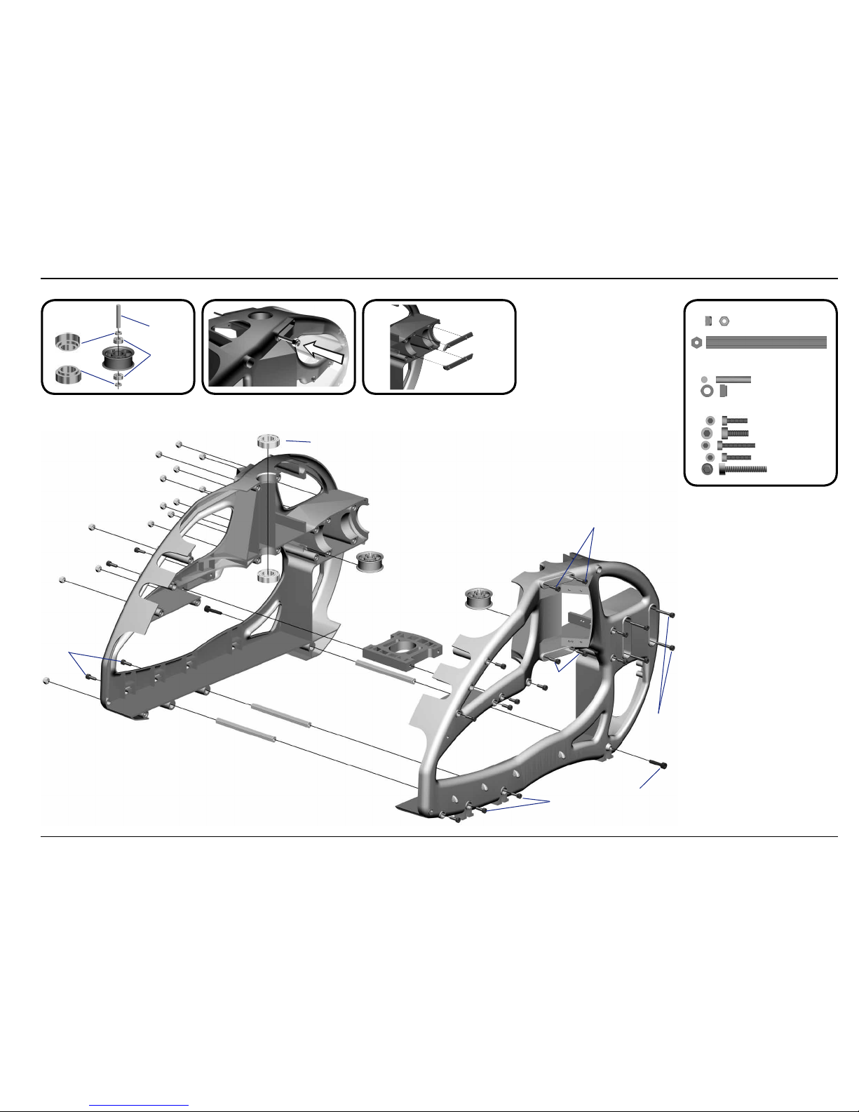
Using the rod M2.5x60 from bag 7, position all 14
nylon nuts in the right side frame.
Before you combine the two sides of the main
frame, attach the two belt tensioners (#4089,
bag 6).
1 Mainframe
Bag 1
Bag 1
All parts shown in the boxes are displayed in real size.
Page 4
Manual LOGO 600 - ©Mikado Model Helicopters GmbH - Page 4
4x M3
1x M2,5x6
1x 5x26,5
2x M3x8
4x
M3x35
M3x14
M2x8
3x6x2,5
3x5x0,5
3x5x5
M3 Stopp
(4x)
5x22,3
5x13x4
M2,5x6
M3x35 (4x)
M3x8
M3x16
4x8x2
6x8x0,5
M2,5x6
M3 Stopp
2,5x6x0,5
1x 3x5x5
1x M2x8
1x
Kugel/ball/Rotule Ø4,8x2
1x
3x5x0,5
1x M3x14
2x
3x6x2,5
2x
6x8x0,5
2x M2,5x6
2x
2,5x6x0,5
2x 4x8x3
2x
4x8x2
2x M3x16
2x
4x8x3,5
2x
M3
Ball Ø6 mm
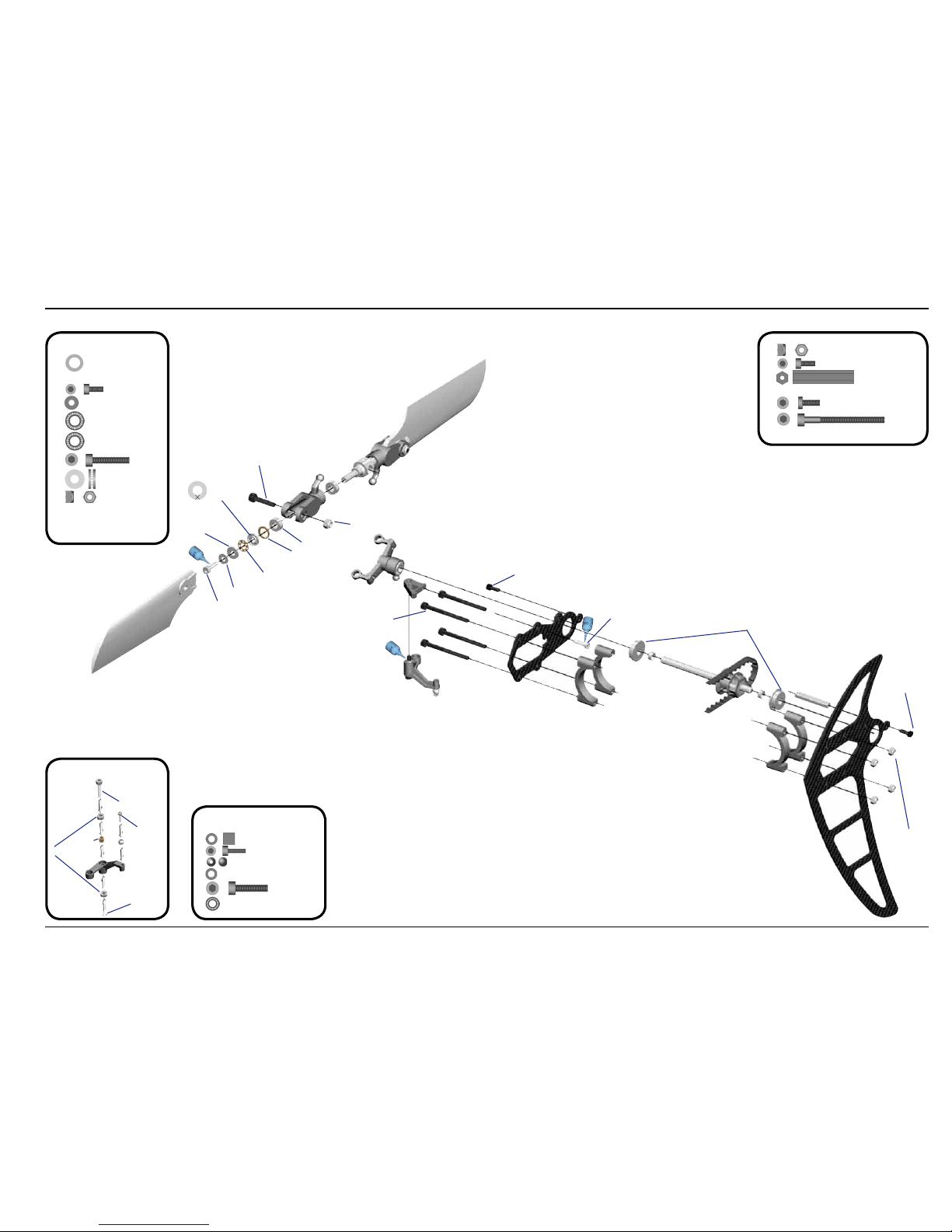
2 Tail Rotor
Bag 5
Bag 5
Bag 5
Apply grease
to bearing
Small inner
diameter
Large inner
diameter
Glue ball bearings using 5min Epoxi.
Page 5

Manual LOGO 600 - ©Mikado Model Helicopters GmbH - Page 5
2x M3
1x M2x6
1x M2 Stop
2x M2,5x30
4x
Kugel/ball/Rotule Ø6x3
2x
M3x40
M3x40
M2x6
M2 Stop
M3x3
M2,5x30 (2x)
Ø4x705 mm
Ø5x520 mm
3 Tail Boom
Bag 6
Bag 5
Bag 6 + 11
Bag 6 + 11
Ball Ø6 mm
Ball Ø6 mm
Attach the ball links so that the engraved
number is on the outer surface pointing towards you.
5 Min. Epoxy
5 Min. Epoxy
Page 6

Manual LOGO 600 - ©Mikado Model Helicopters GmbH - Page 6
5
4x M3
4x M3x10
4x M3x3
1x
4x M3x8
1x 10x16x0,2
1x 10x16x0,5
1x 3x16
1x M2,5x8
4
10x16x0,2
10x16x0,5
M3x8
(4x)
M3x10
M3x10
M3 Stopp (4)
M3x20
(7x)
1x 2,2x6
Secure scids using set screws 3x3.
Tighten tooth belt:
Pull tail rotor backwards and tighten screws
Grease
autorotation hub
4 Main Gear & Tail Boom Assembly
Bag 2 • Bag 3 • Bag 6 • Bag 8
Bag 2
Swashplate bag 3
Bag 8
Tighten the pivot bolts
very carefully. Do not
overtighten them, as
they will break off.
Attach the tail boom with a screw 2.2x6
Push in tail boom until locked.
Page 7

Manual LOGO 600 - ©Mikado Model Helicopters GmbH - Page 7
1x M3x45
2x
3x5x1,2
4x
M2,5x10
12x 2,2x13
2x M2x10
1x M2x12
4x
9x M2
3x M2,5x30
2,2x13 (4x)
18 mm
(4x)
2,2x13
(4x)
M2,5x10 (4x)
4
5
6
7
9
5 Servo Installation
Bag 1 • Bag 9
Bag 9
Bag 1
Bag 9
Bag 1
Apply a small amount
of oil to the rotor shaft.
If you are installing Futaba servos, add the
distance plate for the two aileron servos.
Aileron left Aileron right
Elevator
Rudder
LOGO Rotor Head (V-Stabi, flybarless head)
16 mm 16 mm 16 mm 14 mm
Attach the ball links so that the engraved
number is on the outer surface pointing
towards you.
Page 8

Manual LOGO 600 - ©Mikado Model Helicopters GmbH - Page 8
5x M3x8
6x 3x8
2x 8x11x0,5
4x 8x16x5
2x 8x16x5
2x
11,5x16x1
2x M3x10
1x M3x20
2x M3x35
2x M5x12
2x M4x35
2x
5x15x1
3x M3
2x M4
2x Ø4,8x3
2x 3x12
4x 3x7x3
4x 3x6x2,5
2x 3x5x2
2x M3x14
1x M3x5
2x 3x5x0,3
4
7
8
9
5
6
M3x8 (5x)
M3 Stopp
M3 Stopp
M3x20
3x12
(5x)
48 mm
M3x10
M3x35
3x7x3
3x5x2
3x6x2,5
M3x14
M3x5
3x5x0,3
8x11x0,5
3x8
2x
M5x12
M5x12
10x14x1
8x14x4
11,5x16x1
11,5x16x1
6 V-Bar Rotor Head 600
Bag 7
Bag 7
Please adjust the swashplate driver in such a way
that the balls on the inner and outer ring of the
swashplate are positioned exactly on a line along
the longitudinal axis of the heli.
Large inner
diameter
Small inner
diameter
Apply grease to bearing
If the blade holder shows axial
play, use one shime 10x16x0.5.
If the blade holder shows axial
play, use one shime 10x16x0.5.
Page 9

Manual LOGO 600 - ©Mikado Model Helicopters GmbH - Page 9
2x 4x8x1
2x M4x14
7 Mounting the Motor 8 Mounting the Canopy
Bag 1Bag 1
Installation of the Motor Pinion
Screw the motor pinion onto the motor shaft, making sure that
it can still be moved. Now mount the motor on the motor plate
and move the pinion so it is aligned well with the main gear.
As visual help for aligning the pinion you may use the small
ridge which separates the two parts of the pinion. When the
pinion is aligned correctly it will easily engage with the main
gear. If the pinion does not engage with the main gear, it is not
correctly aligned. After the pinion is correctly aligned, take the
motor out of the mainframe and tighten the set screw.
Gear Backlash
Move the motor with the pinion until it is limited by the gear.
Tighten one of the M4x14 screws slightly. You must still be able
to swivel the motor around its own axis. In this way you can
easily determine the correct distance between the main gear
and the pinion. There should be no (!) gear backlash. At the
same time, the motor should not (!) exert any pressure onto the
running surface of the main gear. After you have determined
the correct distance, tighten the second M4x14 screw.
Bag 1
available pinions for
module 1 diameter 6 mm
(not included in kit)
10 teeth* #4410
11 teeth #4411
12 teeth #4412
13 teeth #4413
14 teeth #4414
15 teeth #4415
*diameter 5 mm
For very hard 3d flying counterbearing
no. #4373 (30 mm, 6 mm shaft)
should be installed.
Bag 1
Page 10

Manual LOGO 600 - ©Mikado Model Helicopters GmbH - Page 10
4 5
6
87
9 Radio and Battery
Battery:
Attach the battery with the 3
Velcros.
Position of servo arms for the tail rotor when sticks are centered
Position of servo arms for the aileron servos
when sticks are centered (0 deg. Pitch)
Velcro
V-Bar Main board
Receiver
Position for mounting V-Bar gyro
Position of LiPo battery
for the power supply of receiver.
speed
controller
Page 11

Manual LOGO 600 - ©Mikado Model Helicopters GmbH - Page 11
LOGO 600 #04366
10 Overview Chassis
Page 12

Manual LOGO 600 - ©Mikado Model Helicopters GmbH - Page 12
11 Overview Tail Rotor
Page 13

Manual LOGO 600 - ©Mikado Model Helicopters GmbH - Page 13
Construction & Rendering: Mehran Mahinpour Tirooni • Layout & Realisation: CDT-Berlin
www.mikado-heli.de
12 Overview V-Bar Head
 Loading...