

Page 1
www.mikado-heli.de
LOGO 400 SE
©Mikado Model Helicopters GmbH, V2.0
Manual
Mikado Model Helicopters GmbH • Friedrich-Klausing-Straße 2 • 14469 Potsdam • Germany
Phone +49 (0)331 23749-0 • Fax +49 (0)331 23749-11 • www.mikado-heli.de
Page 2

Manual LOGO 400 SE Page 2 ©Mikado Modellhubschrauber
Details
Page 3
Manual LOGO 400 SE Page 3 ©Mikado Modellhubschrauber
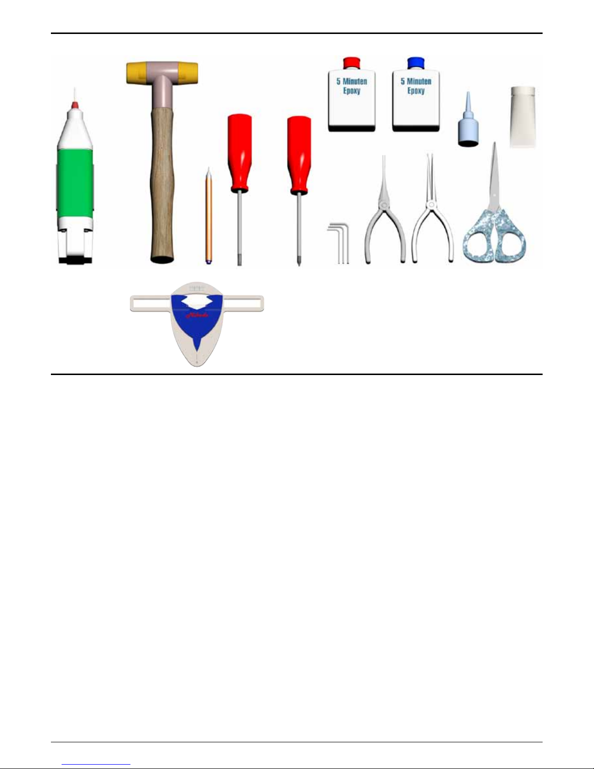
Tools for Assembly & R/C Equipment
Scissors
Rubber Hammer
Drill with
1.5mm bit
(.059 in)
Marker
Screwdrivers
(plus and minus)
Hex Wrenches
1.5/2.0/2.5/3.0 mm
(.055/.079/.098/.118 in)
Ball
link
pliers
Threadlock
Ball
link
pliers
Grease
Pitch Gauge
Safety Instructions
OPERATING YOUR MODEL SAFELY
Operate the helicopter in spacious areas with no people nearby. !Warning: Do NOT operate the helicopter in the following
places and situations (or else you risk severe accidents):
• in places where children gather or people pass through
• in residential areas and parks indoors and in limited space
• in windy weather or when there is any rain, snow, fog or other
precipitation
If you do not observe these instructions you may be held reliable
for personal injury or property damage!
Always check the R/C system prior to operating your helicopter.
When the R/C system batteries get weaker, the operational range
of the R/C system decreases. Note that you may lose control of
your model when operating it under such conditions.
Keep in mind that other people around you might also be operating
a R/C model. Never use a frequency which someone else is using
at the same time. Radio signals will be mixed and you will lose
control of your model.
If the model shows irregular behavior, bring the model to a halt
immediately. Turn off all power switches and disconnect the batteries. Investigate the reason and x the problem. Do not operate
the model again as long as the problem is not solved, as this may
lead to further trouble and unforeseen accidents.
! Warning: In order to prevent accidents and personal injury, be
sure to observe the following:
Before ying the helicopter, ensure that all screws are tightened.
A single loose screw may cause a major accident.
Replace all broken or defective parts with new ones, as damaged
parts lead to crashes. Never approach a spinning rotor. Keep at
least 10 meters/yards away from a spinning rotor blades. Do not
touch the motor immediately after use. It may be hot enough to
cause burns. Perform all necessary maintenance.
PRIOR TO ADJUSTING AND OPERATING YOUR MODEL,
OBSERVE THE FOLLOWING
! Warning: Operate the helicopter only outdoors and out of
people’s reach as the main rotor operates at high rpm!
! Warning: While adjusting, stand at least 10 meters/yards away
from the helicopter!
Novice R/C helicopter pilots should always seek advice from
experienced pilots to obtain hints with assembly and for pre-ight
adjustments. Note that a badly assembled or insufciently adjusted helicopter is a safety hazard! In the beginning, novice R/C
helicopter pilots should always be assisted by an experienced
pilot and never y alone! Throttle channel should be in motor OFF
position while powering up. When switching the R/C system ON
or OFF, always proceed in the following order:
When switching ON:
Position the throttle control stick (on transmitter) to a position
where the LOGO 10 motor does not operate.
• Turn on the transmitter.
• Turn on the receiver.
• Connect the motor battery.
• Operate your model.
When switching OFF:
• Turn off the motor (move throttle control to a position where
motor does not operate).
• Wait until the rotor head has stopped spinning.
• Disconnect the motor battery.
• Turn off receiver.
• Turn off transmitter.
Page 4
Manual LOGO 400 SE Page 4 ©Mikado Modellhubschrauber
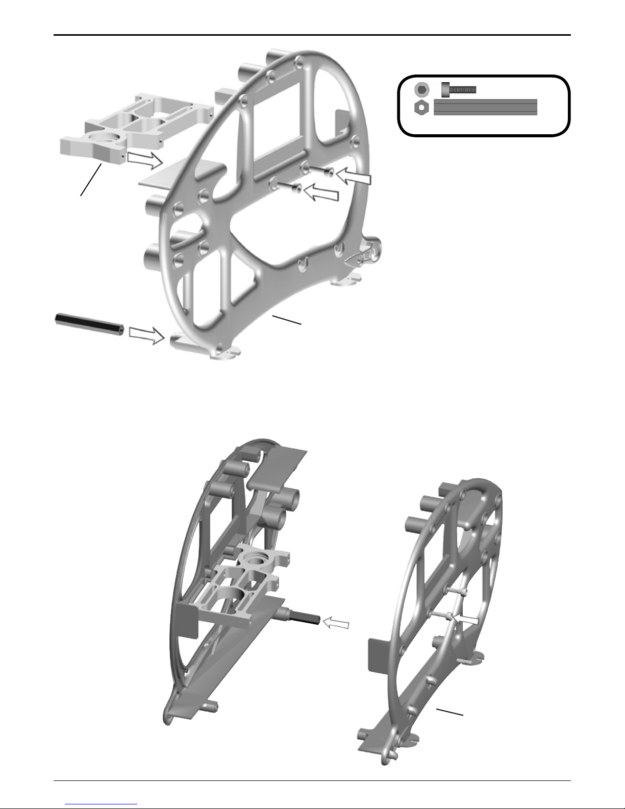
#4187
#4170
#4188
4x M3x10 #1953
1x
38 mm #2371
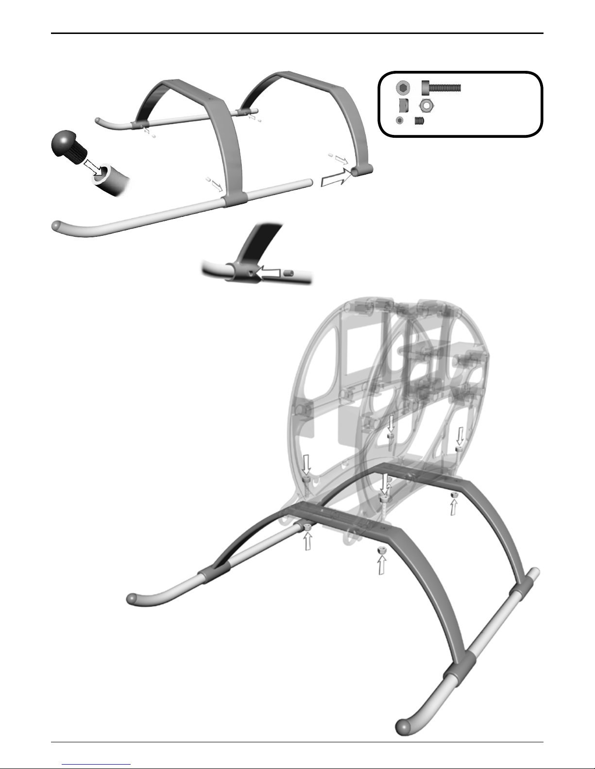
1 Main Frame
1.1 Main Frame
Bag 1 • Bag 12
Page 5
Manual LOGO 400 SE Page 5 ©Mikado Modellhubschrauber
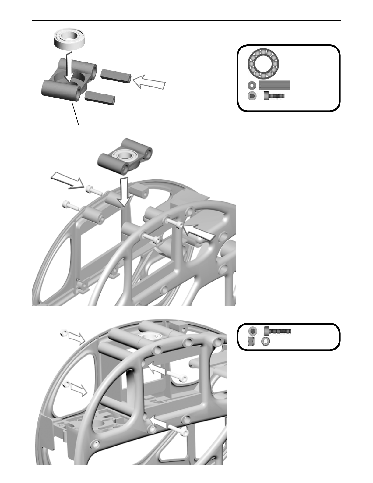
1x 10x19x5 #1329
2x
19 mm #2371
4x
M3x10 #1953
#2380
2x M3x14 #1955
2x
M3 Stopp #2074
1 Main Frame
1.2 Bearing Case
Bag 1 • Bag 10 • Bag 12
Page 6
Manual LOGO 400 SE Page 6 ©Mikado Modellhubschrauber
4x M3x12 #1954
4x
M3 #2074
4x
M3x3 #1920
2 Landing Gear
Bag 8 • Bag 12
Page 7
Manual LOGO 400 SE Page 7 ©Mikado Modellhubschrauber
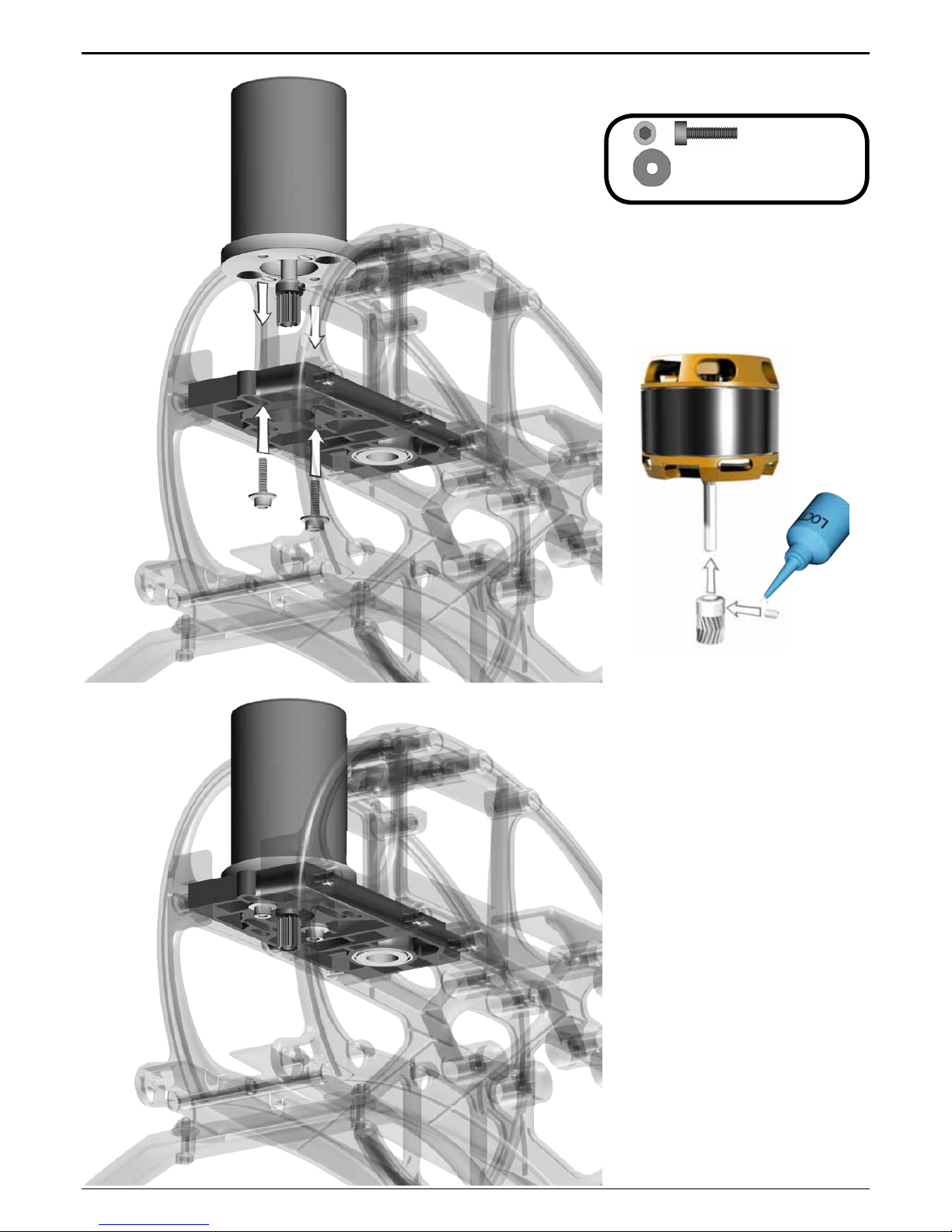
2x M3x12 #1954
2x
3x9x1 #2011
3 Motor Installation
3.1 Motor Attachment
Bag 1 • Bag 12
When installing the motor, tighten
the socket head cap screws only
slightly, making sure that the motor
can still be moved on the motor
plate.
Do not tighten the set screw fully until
the nal position of the pinion on the
motor shaft is determined. This is
done after installing the main gear.
There are two options for attaching
the pinion:
1. For securing the pinion, you may
atten the motor shaft where the set
screw meets the motor shaft - without
making a at surface on the motor
shaft.
2. Alternatively, you may screw the
set screw directly onto the motor
shaft. For this it is required that the
set screw has an appropriate rim for
engaging the motorshaft (all Mikado
pinions have this rim). Note, however,
that after attaching the set screw
once, the rim becomes blunt and may
not be used again.
Page 8

Manual LOGO 400 SE Page 8 ©Mikado Modellhubschrauber
#2731
#2725
4x M3x8 #1915
4x
10x16x0.5 #2010
1x M,5x8 #1940
1x
#1344
#04177
4 Main Gear
4.1 Hub
Bag 2
Page 9
Manual LOGO 400 SE Page 9 ©Mikado Modellhubschrauber
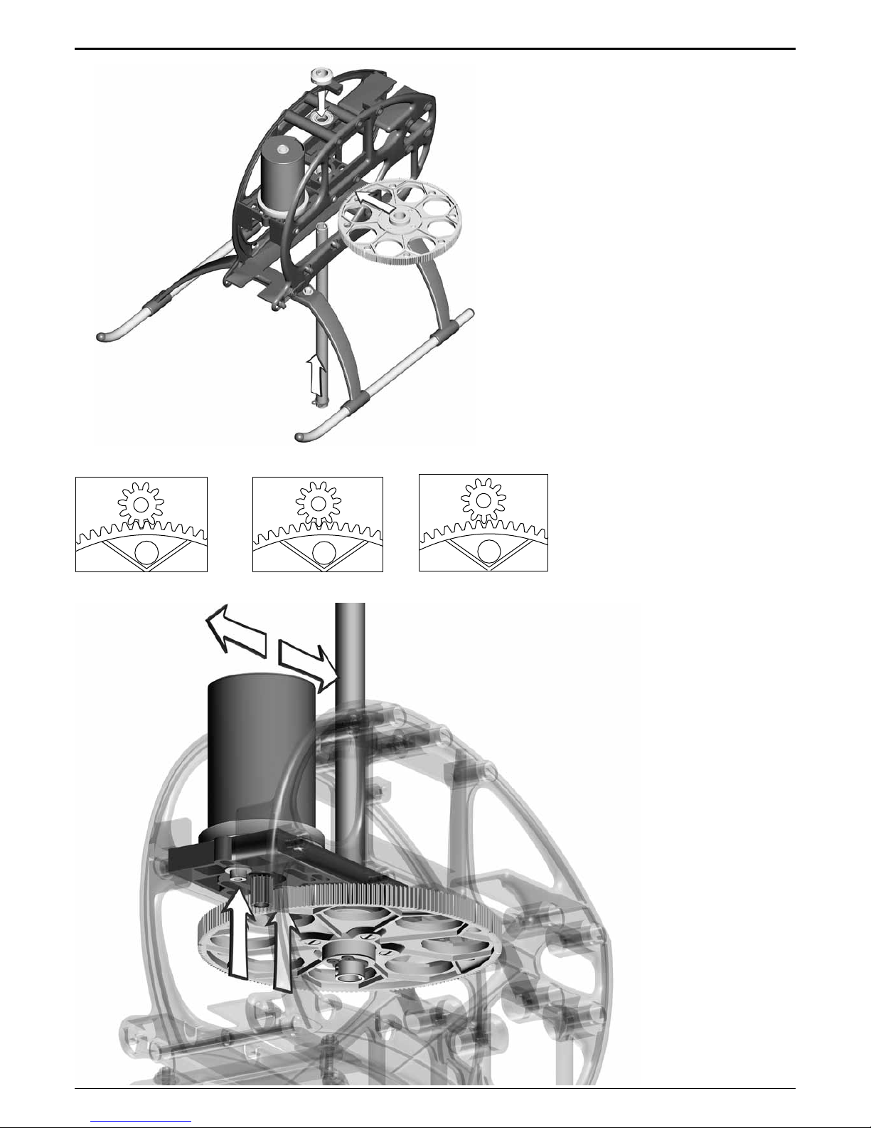
4 Main Gear
After having attached the freeway
hub of the main gear to the rotor
shaft, pull the rotor shaft slightly
upward and simultaneously push
the main shaft collar down onto ball
bearing. Next tighten the set screws.
The rotor shaft should turn easily and
it should not have any axial play.
4.2 Adjusting Gear Backlash
The gear backlash must be adjusted (see drawings). Excess backlash can cause premature wear of
the main gear and will lead to shorter
ight times.
too much backlash correct backlash too little backlash
Page 10
Manual LOGO 400 SE Page 10 ©Mikado Modellhubschrauber
# 4189
# 4181
#2467
#2476
#2466
#2189
#4150
1x 2x10mm #2469
2x
5x10x4 #2470
2x
5x10x0.1 #2004
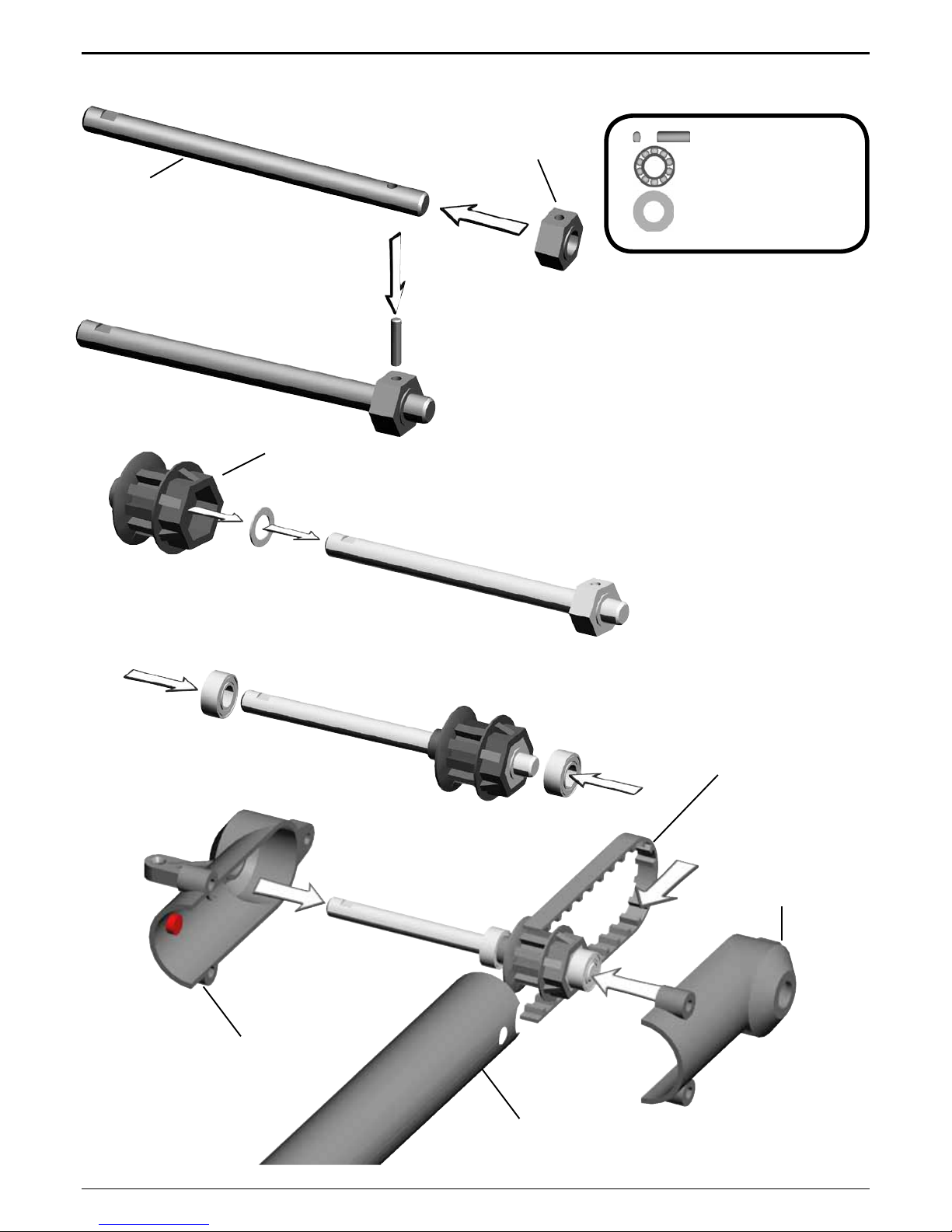
5 Tail Rotor
5.1 Tail Rotor Shaft
Bag 5 • Bag 10
Should you have difculty mounting
the 2x10 mm pin, carefully tap it with
a rubber hammer, or use a vice. The
5x10x4 bearings can also be mounted on the rotor shaft using a vice and
tapping the shaft softly with a rubber
hammer. If the tail rotor shaft shows
axial play after closing the two halves
of the tail rotor case, use one or two
of the 5x10x0.1 washers which are
included in the bag.
Page 11

Manual LOGO 400 SE Page 11 ©Mikado Modellhubschrauber
#4182
2x M3x25
#1958
1x
M3x10 #1953
3x
M3 #2074
5 Tail Rotor
5.2 Vertical Fin
Bag 5 • Bag 12
Page 12

Manual LOGO 400 SE Page 12 ©Mikado Modellhubschrauber
#2455
#2452
2x 6x10x2,5 #1440
#3030
2x7mm
5 Tail Rotor
5.3 Pitch Slider
Bag 5 • Bag 10
It is important that the tail pitch plate #3030 is aligned properly on the
control sleeve #2455. In the case of
misalignment, the control sleeve may
become deformed.
The mounted tail pitch plate should
be able to move on the tail rotor shaft
with little resistance.
Page 13

Manual LOGO 400 SE Page 13 ©Mikado Modellhubschrauber
#2449
2x 3x6x2,5 #2330
1x
M3x14 #1955
1x
M2x8 #1902
1x
#1570
1x
3x5x5 #2448
1x
3x5x0,5 #2002
5 Tail Rotor
5.4 Tail Rotor Lever
Bag 5 • Bag 12
The mounted tail rotor lever should
be able to move with little resi-
stance.
Page 14

Manual LOGO 400 SE Page 14 ©Mikado Modellhubschrauber
M3x3
M3x16
4x8x3
#2462
4x8x2
#3051
5x8x0,5
M2,5x6
M3 Stopp
2,5x6x0,5
3x M2,5x6
2x
2,5x6x0,5
2x
4x8x3
2x 4x8x2
2x
M3x16
2x 4x8x3,5
2x
M3
1x M3x3
2x
5x8x0,5
5 Tail Rotor
5.5 Tail Rotor Hub
Bag 5 • Bag 10
Small inner
diameter
Large inner
diameter
Apply grease
to bearing
Page 15

Manual LOGO 400 SE Page 15 ©Mikado Modellhubschrauber
#2485
6 Tail Boom
6.1 Tail Boom Holder
Bag 6
Turn the tail drive belt 90° degrees
(clockwise).
Page 16

Manual LOGO 400 SE Page 16 ©Mikado Modellhubschrauber
#2728
1x 4x13x5 #937
1x
4x9x4 #2489
2x 4x8x1 #2013
1x
3x5 #1921
1x
M3x18 #1965
1x
M3 #2074
#2488
!
6 Tail Boom
6.2 Tail Drive Pulley
Bag 6 • Bag 10 • Bag 12
Important: Check belt tension
prior to every ight. Incorrect belt
tension can cause disturbances
for your model R/C system. Incorrect belt tension can lead to a
situation where you lose control of
the tail rotor of your helicopter.
For tightening the belt pull the tail
boom holder toward the front. Belt
tension is xed with the M3x18 sokket head cap screw for tightening the
tail boom holder to the tail boom. The
belt should be tight. When pressing
with your ngers, both sides of the
belt should not come in contact with
each other.
Page 17

Manual LOGO 400 SE Page 17 ©Mikado Modellhubschrauber
#4179
5 Min. Epoxy
1x M2x6 #1901
1x
M2 #2070
2x
M2,5x30#2770
6 Tail Boom
6.3 Tail Control Rod
Bag 6
Screw the two 2 mm ball links onto
the control rods. Their exact positions
are of no importance at this point. The
ball ends are attached to the balls
more easily when the text on them is
pointed away from the helicopter.
Page 18

Manual LOGO 400 SE Page 18 ©Mikado Modellhubschrauber
8x M3 x12 #1954
2x
27,5 mm
#2371
2x
23 mm
#2371
2x
M3x16 #1956
2x
M3 #2074
#4184
#4184
6 Tail Boom
6.4 Installation
Bag 6 • Bag 12
For mounting the tail assembly in
the side-frames, pull the rear ends of
the side-frames apart.
For adjusting the gear backlash,
insert a strip of paper between the
main gear and the drive pulley, then
press the drive pulley against the
main gear.
6.5 Tail Rotor Blades
Bag 5
Tighten the screws holding the
tail rotor blades, but ensure that the
blades move easily in the tail rotor
holders under centrifugal force.
Page 19

Manual LOGO 400 SE Page 19 ©Mikado Modellhubschrauber
2x 2,9x19
2x
M3 #2074
4x
4,8 mm #1574
4x
M2,5x30 #2770
2x
M3x20 #1957
2x
3x5x2 #2463
#4178
#1565
#4182
2,9x19
6 Tail Boom
6.6 Tail Boom Brace
Bag 1 • Bag 6 • Bag 9
5 min epoxy
The ball links should be screwed
onto the control rod such that one is
turned at 90 degrees with respect to
the other.
Page 20

Manual LOGO 400 SE Page 20 ©Mikado Modellhubschrauber
7 Finished Main Frame & Tail Boom
Page 21

Manual LOGO 400 SE Page 21 ©Mikado Modellhubschrauber
2x M2x8 #1902
2x
M2x10 #1903
6x
M2 #2070
4x
4,8 #1570
14-15 mm
16-17 mm 16-17 mm 16-17 mm
(7x)
8 Swashplate
Bag 3
9 Servo Arms
Bag 9
Rudder Servo Elevator Servo Aileron Servo Aileron Servo
Tighten the pivot bolts
very carefully. Do not
overtighten them, as
they will break off.
120° CCPM
Rudder Servo Elevator Servo Aileron Servo left Aileron Servo right
Page 22

Manual LOGO 400 SE Page 22 ©Mikado Modellhubschrauber
14 mm
(.472 in)
#2770
10 Servo Installation
10 .2 Tail Rotor Servo
With LOGO 400 side-frames you
can use two different sizes of tail
rotor servos. A larger standard-size
tail rotor servo can be mounted to the
left side-frame, a smaller mini servo
is mounted to right side-frame.
10.3 Elevator Servo
Linkage measurements for 3D
pitch range (-12° to +12°)
10.1 Linkage
Bag 9
Page 23

Manual LOGO 400 SE Page 23 ©Mikado Modellhubschrauber
#2383
#2384
#2382
10 Servo Installation
10.4 Elevator Linkage/Swashplate
10.5 Canopy Fixing Bolts
Bag 1
Page 24

Manual LOGO 400 SE Page 24 ©Mikado Modellhubschrauber
10 Servo Installation
10.6 Aileron Servo left
10.7 Aileron Servo right
Page 25

Manual LOGO 400 SE Page 25 ©Mikado Modellhubschrauber
10 Servo Installation
10.8 Aileron Linkage
Page 26

Manual LOGO 400 SE Page 26 ©Mikado Modellhubschrauber
5x M3x8
2x
3x7
2x
2,5x7
2x
8x11x4
2x
8x11x1
4x
8x14x4
2x
6x14x5
2x
10x14x1
2x
M3x10
1x
M3x20
2x
M3x22
2x
M4x12
2x
M3x24
2x
4x12x1
3x
M3
2x
Ø4,8x3
2x 3x12
4x
3x7x3
4x
3x6x2,5
2x
3x5x2
2x
M3x14
1x
M3x5
2x
3x5x0,3
M4x12
4x12x1
3x7
2,5x7
8x11x1
8x11x4
10x14x1
(5x)
M3x10
M3x8 (5x)
8x14x4
3x12
3x7x3
3x5x2
3x6x2,5
2x
M3x14
M3x5
3x5x0,3
11 VBar Rotorhead
Bag 7
Large inner
diameter
Small inner
diameter
Apply grease to bearing
Page 27

Manual LOGO 400 SE Page 27 ©Mikado Modellhubschrauber
M3 Stopp
M3x20
37 mm
M3x22
Please adjust the swashplate driver in such a
way that the balls on the inner and outer ring of
the swashplate are positioned exactly on a line
along the longitudinal axis of the heli.
11 VBar Rotorhead
Page 28

Manual LOGO 400 SE Page 28 ©Mikado Modellhubschrauber
1x
M3x40
2x
M3x12 #1954
1x
M3x10 #1953
3x M2,5x10 #1938
3x
M2,5 #2071
#4185
M2,5x10
M3x10
M3x12
M2,5x10
M3x12
M3x40
12 Battery Support
Bag 1 • Bag 12
Page 29

Manual LOGO 400 SE Page 29 ©Mikado Modellhubschrauber
13 Overview
13.1 Chassis
Page 30

Manual LOGO 400 SE Page 30 ©Mikado Modellhubschrauber
13 Overview
13.2 Rotor Head
Page 31

Manual LOGO 400 SE Page 31 ©Mikado Modellhubschrauber
www.mikado-heli.de
Construction & Rendering: Mehran Mahinpour Tirooni • Layout & Realisation: CDT-Berlin
13 Overview
13.3 Tail Boom/Tail Rotor
 Loading...