

Page 1
Manual
LOGO 20
www.mikado-heli.de
Mikado Modellhubschrauber • Friedrich-Klausing-Straße 2 • 14469 Potsdam • Germany
Phone +49 (0)331 23749-0 • Fax +49 (0)331 23749-11 • www.mikado-heli.de
© Mikado Modellhubschrauber, V2.0
Page 2

Index
1 Main Frame .........................................5
1.1 Motorplate 5
1.2 Elevator Lever 6
1.3 Motorplate 6
1.4 Bearing Case for Main Shaft 7
2 Landing Gear ...................................... 8
3 Motor Installation ............................... 9
4 Main Gear ..........................................10
4.1 Main Gear Hub 10
4.2 Main Rotor Shaft 11
4.3 Adjusting Gear Backlash 13
5 RC Support .......................................14
5.1 Battery Fixing Rings14
5.2 RC Support14
5.3 Servo Tray 15
5.4 Front Battery Fixing Rings 15
5.5 Frame 16
6 Wash-Out...........................................1 7
7 Swashplate .......................................18
8 Preparation for Servo Installation .19
8.1 Servo Arms 19
8.2 Servo Centering 19
8.3 Elevator and Aileron Servos (2x) 20
8.4 Tail Servo 20
9 Aileron Lever .................................... 21
10 Control Rods ..................................22
10.1 Length of Control Rods 22
10.2 Elevator and Aileron Linkages 22
11 Swashplate Guide Bracket ...........24
12 Installation of Wash-Out Hub ....... 2 4
13 Main Frame without Rotor Head .. 2 5
14 Tail Rotor .........................................26
14.1 Tail Rotor Shaft 26
14.2 Vertical Fin 27
14.3 Tail Pitch Slider 28
14.4 Tail Rotor Lever 29
14.5 Tail Rotor Hub 30
15 Tail ....................................................31
15.1 Tail Boom Assembly 31
15.2 Tail Boom Holder 32
15.3 Tail Dr ive Pulley 33
15.4 Control Rods 34
15.5 Tail Assembly 35
15.6 Tail Rotor Blades 36
15.7 Horizontal Fin 36
15.8 Tail Support 37
16 Finished Main Frame ..................... 38
17 Main Rotor Head ............................ 39
17.1 Blade Grips 39
17.2 Mixing Arms 39
17.3 Yoke 40
17.4 Seesaw 41
17.5 Flybar Control Bridge 42
17.6 Flybar 43
17.7 Flybar Paddles 4 4
17.8 Final Assembly 45
17.9 Rotor Head Linkage 46
17.10 LOGO 20 Finished 48
18 RC Installation ................................49
19 Decals ..............................................51
20 How to Avoid Interference............ 5 2
21 RC Programming ...........................53
22 Rotor Blades ...................................60
22.1 Balancing of Rotor Blades 60
22.2 Static Balancing 60
23 Final Pre-Flight Check ..................61
23.1 Direction of Main and Tail Rotation 61
23.2 Blade Tracking Adjustment 61
24 Control Movements.......................62
24.1 Pitch/Throttle 62
24.2 Rotor Head 62
24.3 Elevator 63
24.4 Aileron 63
25 Overview .........................................64
25.1 Chassis 64
25.2 Rotor Head 65
25.3 Tail Boom/Tail Rotor 65
26 Tuning/Accessories.......................66
Manual
All parts shown in the boxes are displayed in real size.
LOGO 20
Page 2 ©Mikado Modellhubschrauber
Page 3

Safety Instructions
OPERATING YOUR MODEL SAFELY
Operate the helicopter in spacious areas with no people nearby.
!Warning: Do NOT operate the helicopter in the following places and situations
(or else you risk severe accidents):
• in places where children gather or people pass through
• in residential areas and parks
• indoors and in limited space
• in windy weather or when there is any rain, snow, fog or other precipitation
If you do not observe these instructions you may be held reliable for personal injury or property damage!
Always check the R/C system prior to operating your helicopter.
When the R/C system batteries get weaker, the operational range of the R/C system decreases. Note that you
may lose control of your model when operating it under such conditions.
Keep in mind that other people around you might also be operating a R/C model.
Never use a frequency which someone else is using at the same time. Radio signals will be mixed and you will
lose control of your model.
If the model shows irregular behavior, bring the model to a halt immediately. Turn off all power switches and
disconnect the batteries. Investigate the reason and fix the problem. Do not operate the model again as long as the
problem is not solved, as this may lead to further trouble and unforeseen accidents.
!Warning: In order to prevent accidents and personal injury, be sure to observe the following:
Before flying the helicopter , ensure that all screws are tightened. A single loose screw may cause a major accident.
Replace all broken or defective parts with new ones, as damaged parts lead to crashes.
Never approach a spinning rotor. Keep at least 10 meters/yards away from a spinning rotor blades.
Do not touch the motor immediately after use. It may be hot enough to cause burns.
Perform all necessary maintenance.
PRIOR TO ADJUSTING AND OPERATING YOUR MODEL, OBSERVE THE FOLLOWING
!Warning: Operate the helicopter only outdoors and out of people’ s reach as the main rotor operates at high rpm!
!Warning: While adjusting, stand at least 10 meters/yards away from the helicopter!
Novice R/C helicopter pilots should always seek advice from experienced pilots to obtain hints with assembly
and for pre-flight adjustments. Note that a badly assembled or insufficiently adjusted helicopter is a safety hazard!
In the beginning, novice R/C helicopter pilots should always be assisted by an experienced pilot and never fly
alone!
Throttle channel should be in motor OFF position while powering up.
When switching the R/C system ON or OFF, always proceed in the following order:
When switching ON:
• Position the throttle control stick (on transmitter) to a position where the LOGO 10 motor does not operate.
• Turn on the transmitter.
• Turn on the receiver.
• Connect the motor battery .
• Operate your model.
When switching OFF:
• Turn off the motor (move throttle control to a position where motor does not operate).
• Wait until the rotor head has stopped spinning.
• Disconnect the motor battery.
• Turn off receiver.
• Turn off transmitter.
Manual
LOGO 20
Page 3 ©Mikado Modellhubschrauber
Page 4
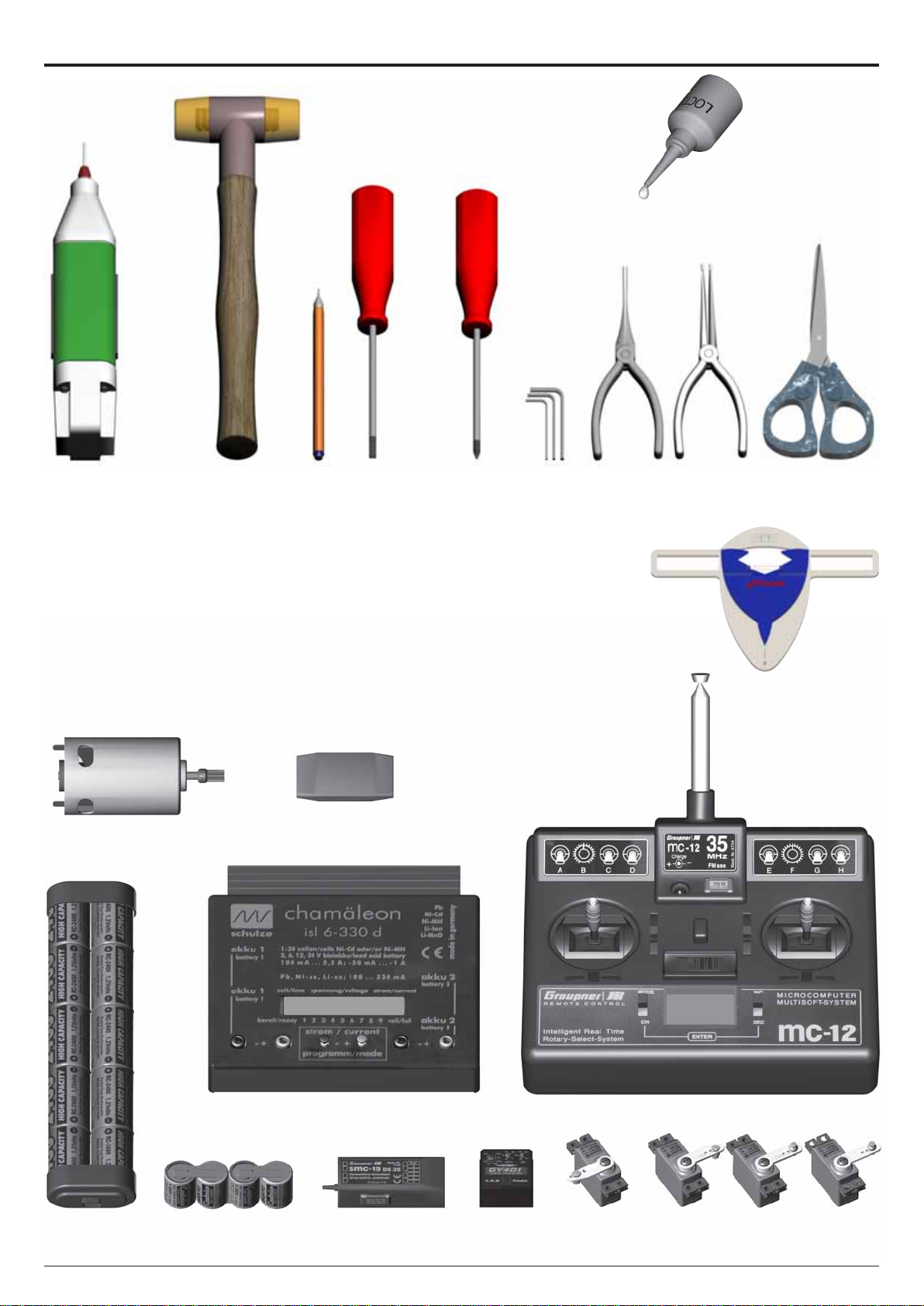
Tools for Assembly & R/C Equipment
Rubber Hammer
Drill with
1.5mm bit
(.059 in)
Marker
Screwdrivers
(plus and minus)
Hex Wrenches
1.5/2.0/2.5/3.0 mm
(.055/.079/.098/.118 in)
Threadlock
Ball link pliers
Scissors
Pitch Gauge
Alle shown products are examples. You may use different brands.
Motor + Speed Controller (check the Mikado
webpages for recommended motors)
Fast Charger (Schulze isl 6-330d or isl 6-636+)
Receiver (Graupner DS 19
or SMC 19 SPCM)
Radio with Heli-Software
Manual
LOGO 20
Battery (Sanyo RC2400 or Sanyo 3000 NiMH)
Receiver Battery
(Sanyo AR500)
Gyro (Futaba GY240
or GY401)
Page 4 ©Mikado Modellhubschrauber
4x Servos
Page 5
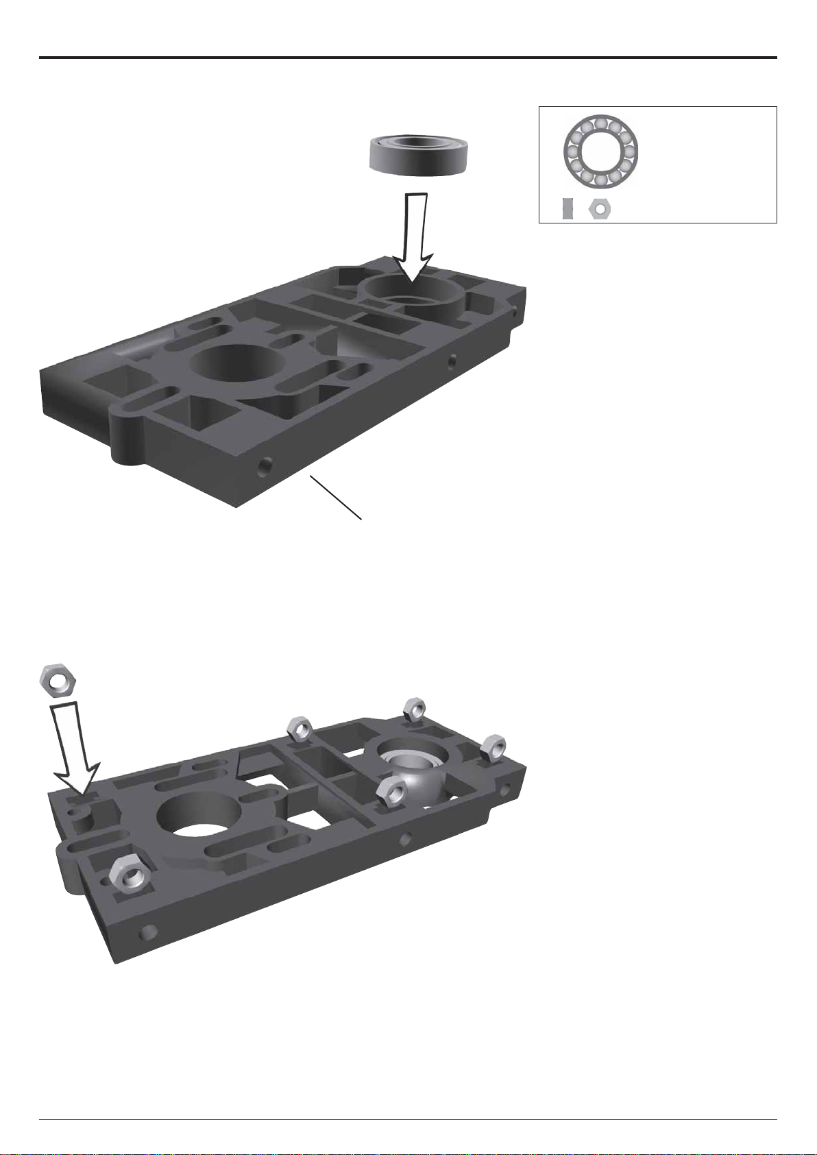
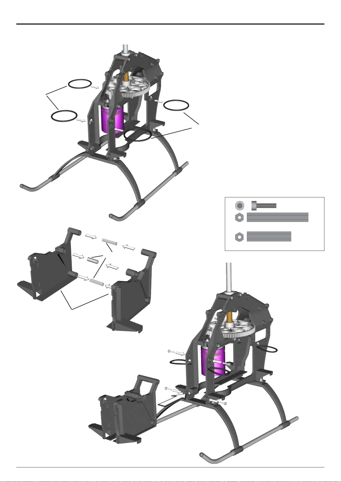
1 Main Frame
1.1 Motorplate
Bag 1 • Bag 10
1x 10x19x5 #1329
#2379
6x
M3 #2072
Manual
LOGO 20
Page 5 ©Mikado Modellhubschrauber
Page 6

#1570
1 Main Frame
1.2 Elevator Lever
Bag 1 • Bag 10 • Bag 12
2x 4x8x3 mm #2397
Choose correct
countersunk screw
#2394
#1570
2x
1x
1x
Ø4,8 mm #1570
M2x8 #1902
M2x10 #1911
1.3 Motor Plate
Bag 1 • Bag 12
4x M3x10 #1953
2x
M3x14 #1955
#2375
#2379
#2376
Manual
LOGO 20
Page 6 ©Mikado Modellhubschrauber
Page 7

1 Main Frame
1.3 Bearing Case for Main Shaft
Bag 1 • Bag 12
2x 19 mm #2370
#2381
4x
M3x12 #1954
Manual
LOGO 20
Page 7 ©Mikado Modellhubschrauber
Page 8
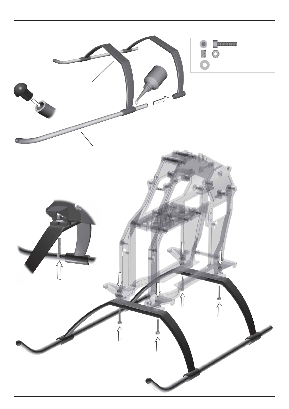
2 Landing Gear
Bag 8 • Bag 12
4x M3x14 #1955
#2495
#2496
4x
4x
Align the skids and secure them
with superglue.
M3 #2074
3x7x0,5 #2012
Manual
LOGO 20
Page 8 ©Mikado Modellhubschrauber
Page 9

3 Motor Installation
3 Motor Installation
Bag 1• Bag 12
2x M3 #2072
Pinion not
included in kit
#2499
2x
2x
2x
Some electric motors are constructed such that they cannot be moved
along the motor plate. If you are using
one of these motors, please use the
motor adaptor plate #2499. The plate
is not needed for Hacker motors.
Please check from the Mikado
website which pinion works best with
the motorset you have (on the Mikado webpage go to LOGO 10 and click
“Motorization”). When a wrong pinion is used, the performance of your
electric helicopter will deteriorate and
the motor or speed controller can be
damaged.
M3x8 #1915
M3x12 #1964
3x7x0,5 #2012
Do not tighten the set screw fully
until the final position of the pinion on
the motor shaft is determined. This is
done after installing the main gear.
There are two options for attaching
the pinion:
1. For securing the pinion, you may
flatten the motor shaft where the set
screw meets the motor shaft - without
making a flat surface on the motor
shaft.
2. Alternatively, you may screw the
set screw directly onto the motor
shaft. For this it is required that the
set screw has an appropriate rim for
engaging in the motorshaft (all Mikado pinions have this rim). Note,
however, that after attaching the set
screw once, this rim becomes blunt
so that the screw may not be used
again.
Manual
LOGO 20
Page 9 ©Mikado Modellhubschrauber
Page 10
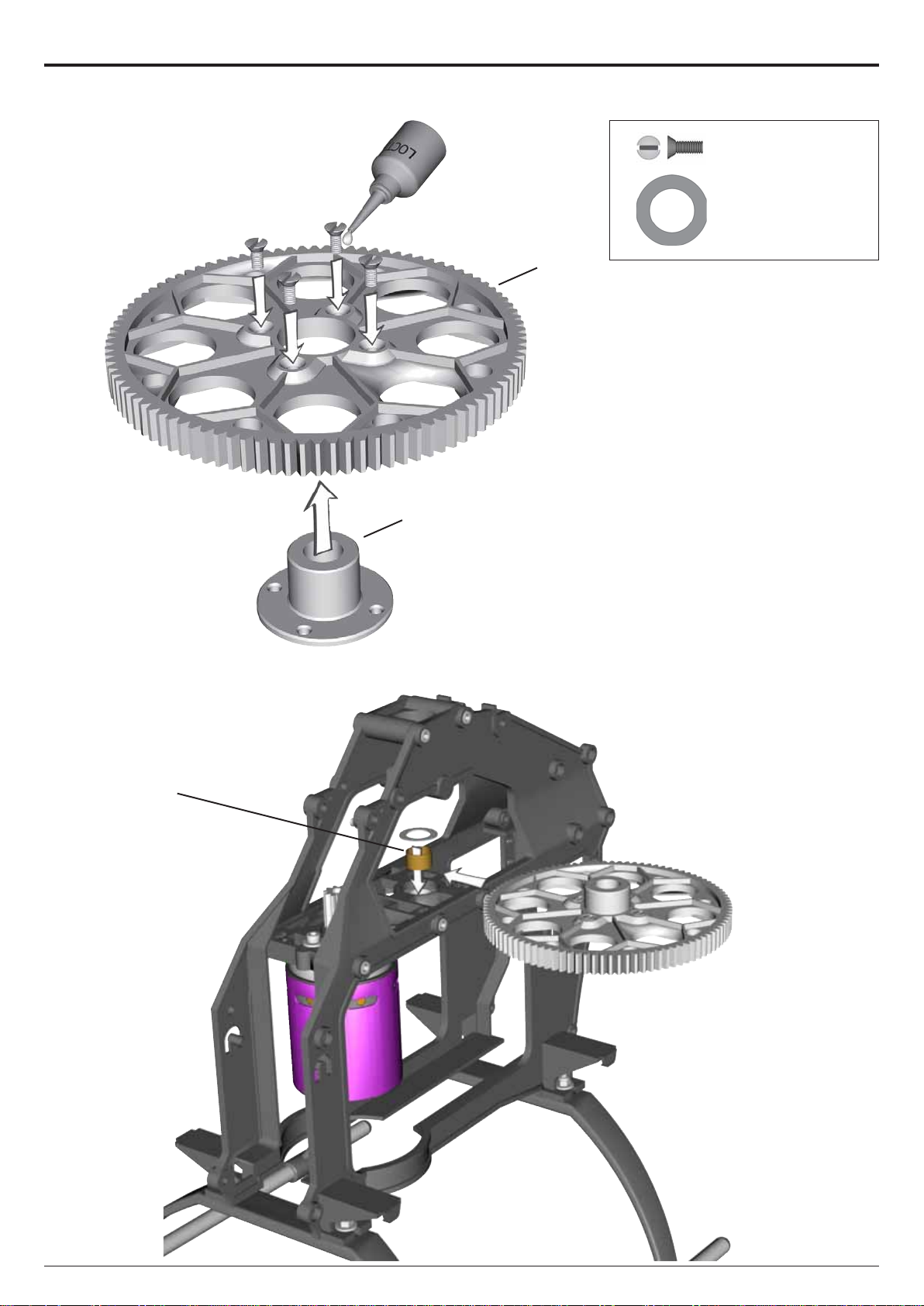
4 Main Gear
4.1 Hub
Bag 2
4x M3x8 #1915
#2410
#3000
1x
10x16x0,5 mm #2010
#2414
Manual
LOGO 20
Page 10 ©Mikado Modellhubschrauber
Page 11
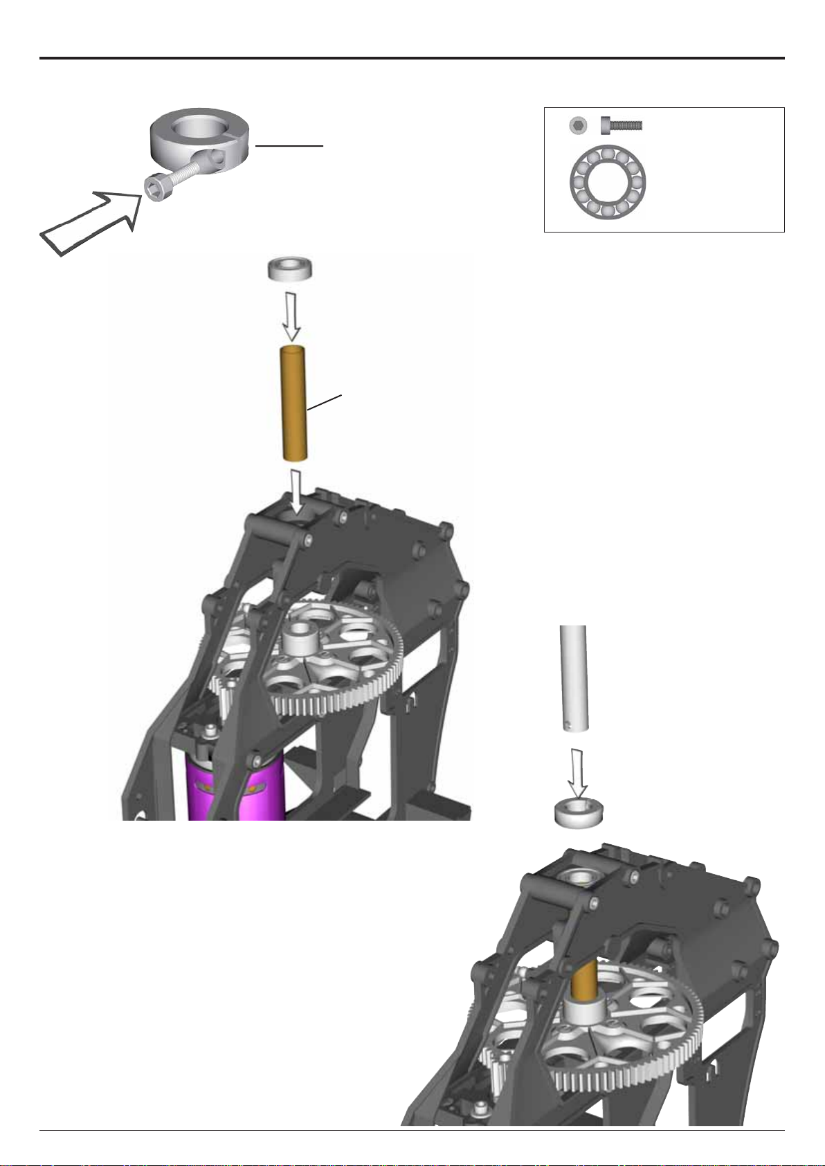
#2385
4 Main Gear
4.2 Rotor Shaft
Bag 2 • Bag 12
1x M2,5x8 #1940
#2414
1x
10x19x5 #1329
Manual
LOGO 20
Page 11 ©Mikado Modellhubschrauber
Page 12
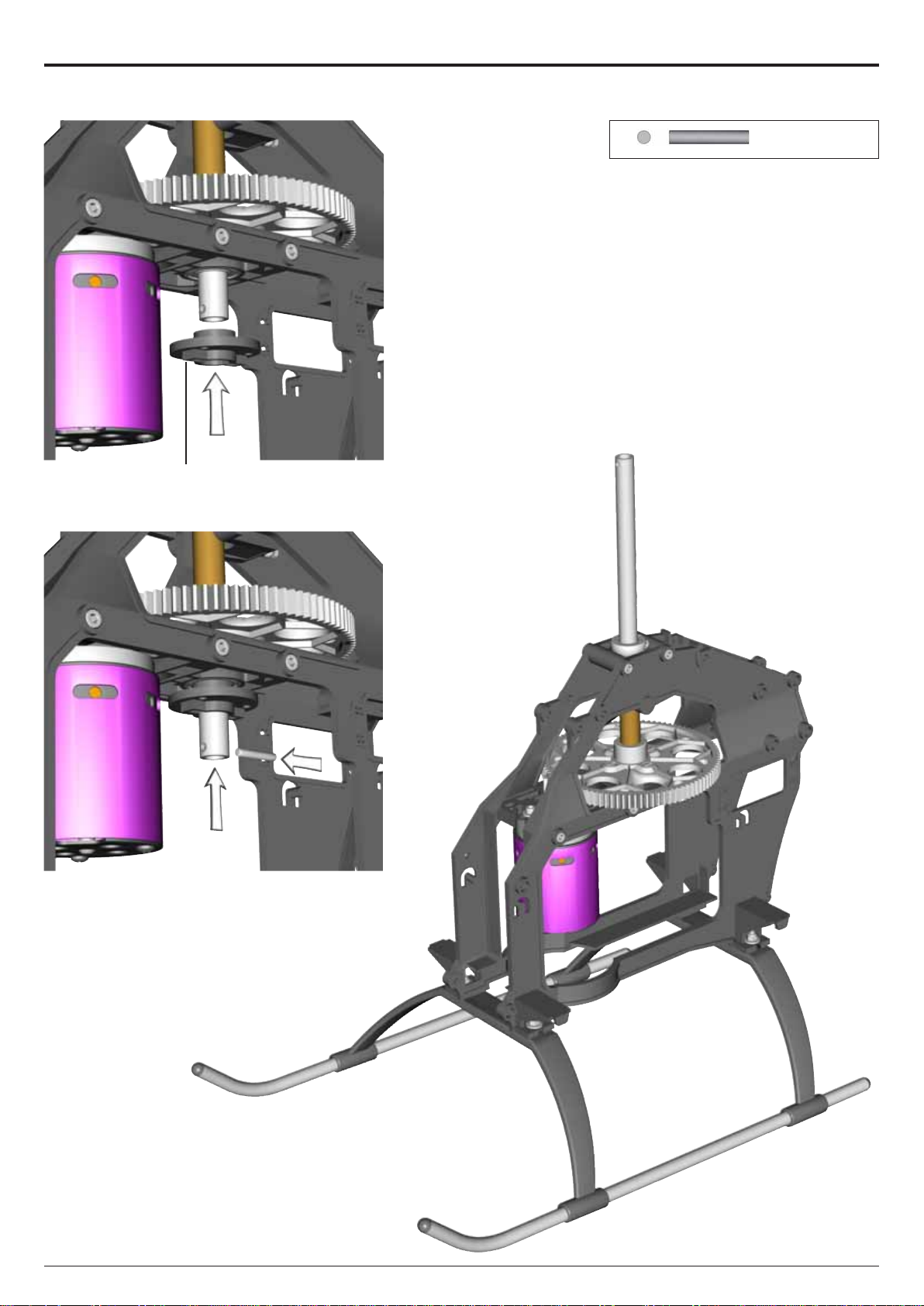
#2389
4 Main Gear
4.2 Rotor Shaft
Bag 2 • Bag 12
1x 3x18 #2388
Manual
LOGO 20
Page 12 ©Mikado Modellhubschrauber
Page 13
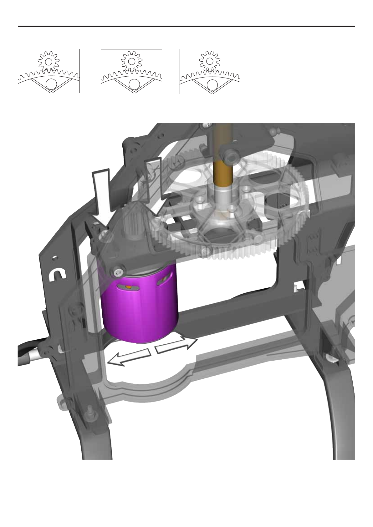
4.3 Adjusting Gear Backlash
too little backlash correct backlash too much backlash
4 Main Gear
The gear backlash must be adjusted (see drawings). Excess backlash can cause premature wear of the
main gear and will lead to shorter flight
times.
Manual
LOGO 20
Page 13 ©Mikado Modellhubschrauber
Page 14
#2425
5 RC Support
5.1 Battery Fixing Rings
Bag 4
#2425
#2420
5.2 RC Support
Bag 4 • Bag 12
4x M3x12 #1954
2x
38mm #2370
1x
27,5mm #2370
#2370
Manual
LOGO 20
Page 14 ©Mikado Modellhubschrauber
Page 15
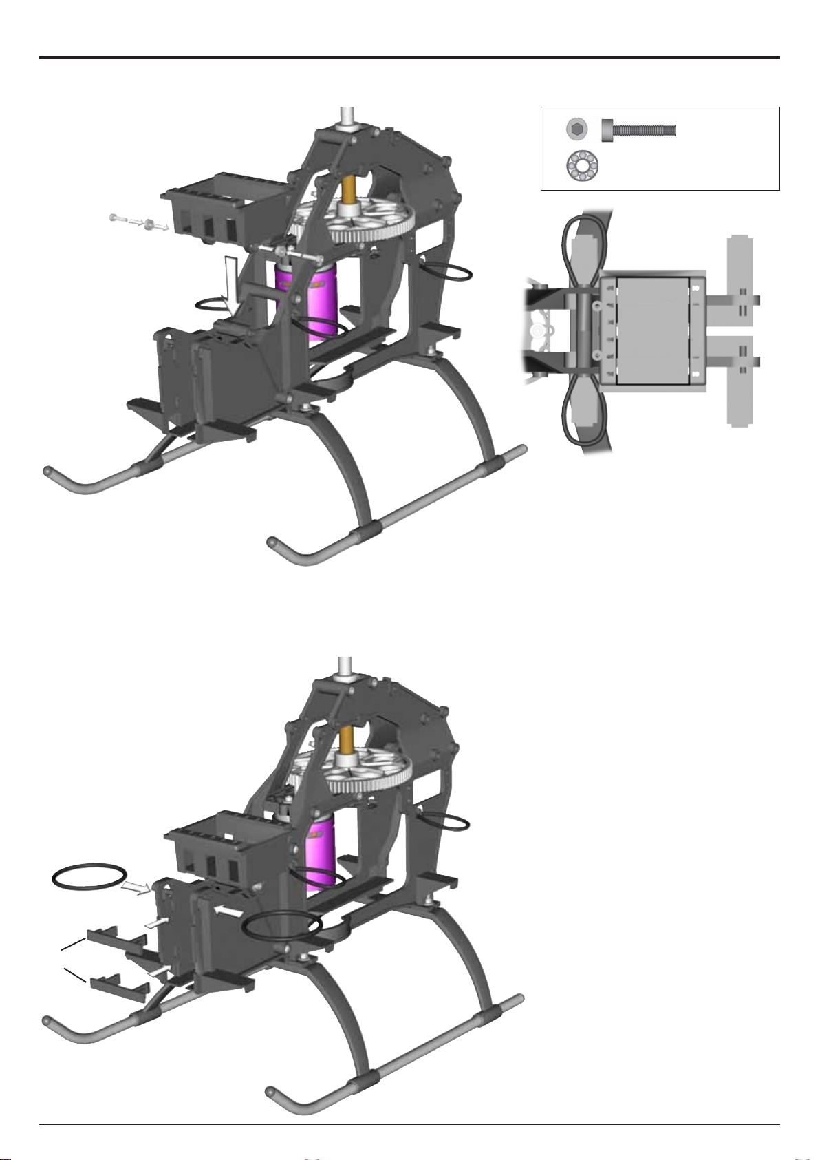
5 RC Support
5.3 Servo Trays
Bag 4 • Bag 10 • Bag 12
2x M3x16 #1956
2x
3x8x3 #2397
#2425
5.4 Front Battery Fixing Rings
Manual
LOGO 20
Page 15 ©Mikado Modellhubschrauber
Page 16
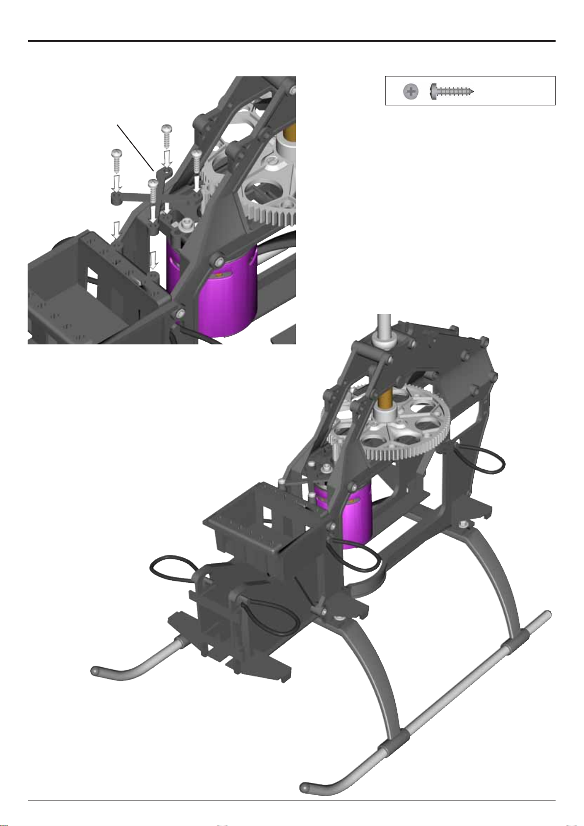
#2424
5 RC Support
5.5 Frame
Bag 4 • Bag 12
4x 2,9x13 #2062
Manual
LOGO 20
Page 16 ©Mikado Modellhubschrauber
Page 17
#981
#979
6 Wash-Out
Assembly
Bag 3 • Bag 10 • Bag 12
2x 2x8mm #980
2x M2x8 #1902
2x
4x 3x7x3 #930
2x
Ø4,8 mm #1570
3x5x2,1 #2463
#1570
2x
2x
move easily on the wash-out.
3x5x0,5 #2002
The Y-rods #981 must be able to
#972
M3x14 #1955
Manual
LOGO 20
Page 17 ©Mikado Modellhubschrauber
Page 18
#1004
#997
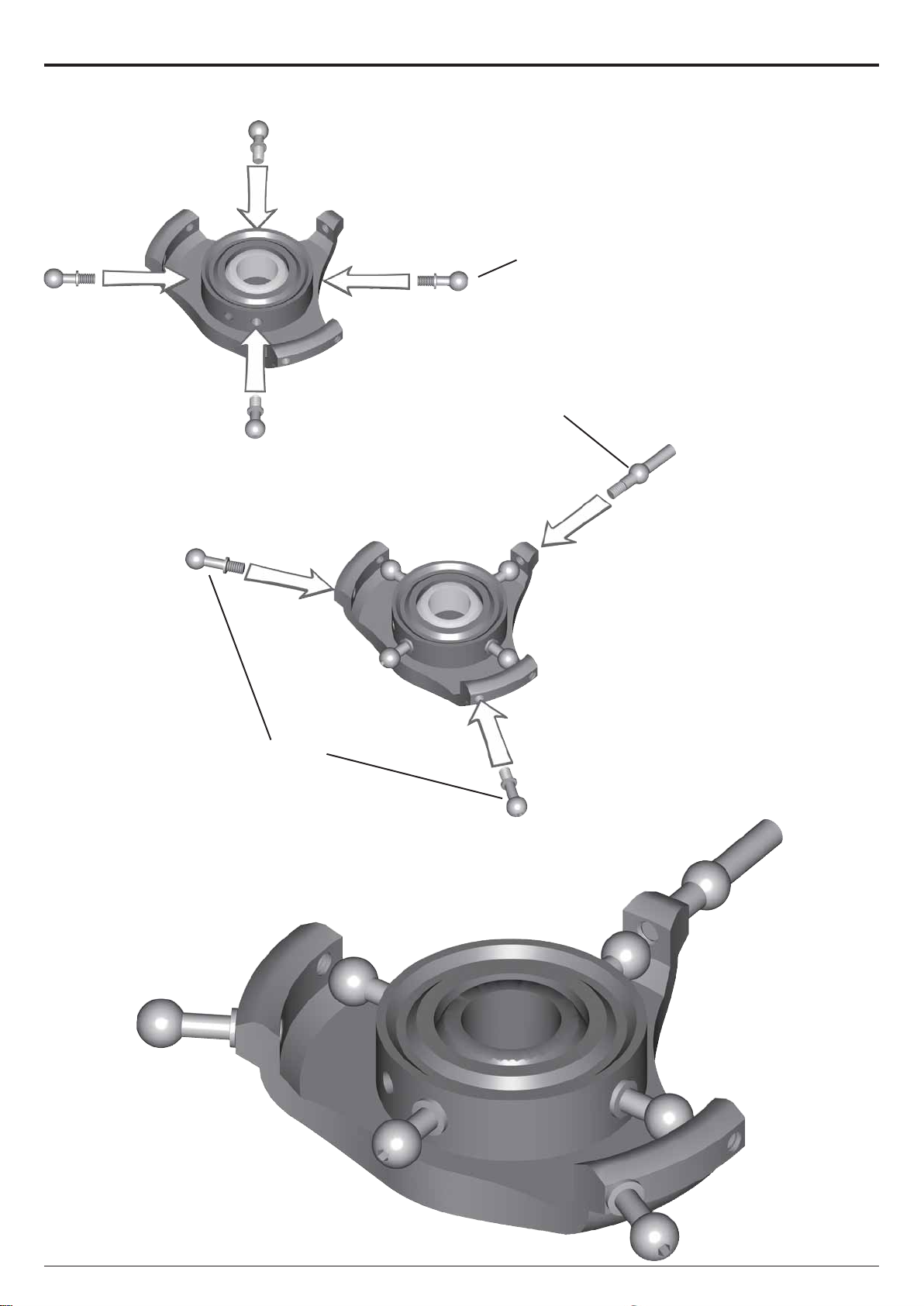
7 Swashplate
Assembly
Bag 3
Secure all pivot bolts with
threadlock.
Important: T ighten the pivot bolts
carefully . Do not overtighten them,
as they will break off.
#1005
Manual
LOGO 20
Page 18 ©Mikado Modellhubschrauber
Page 19
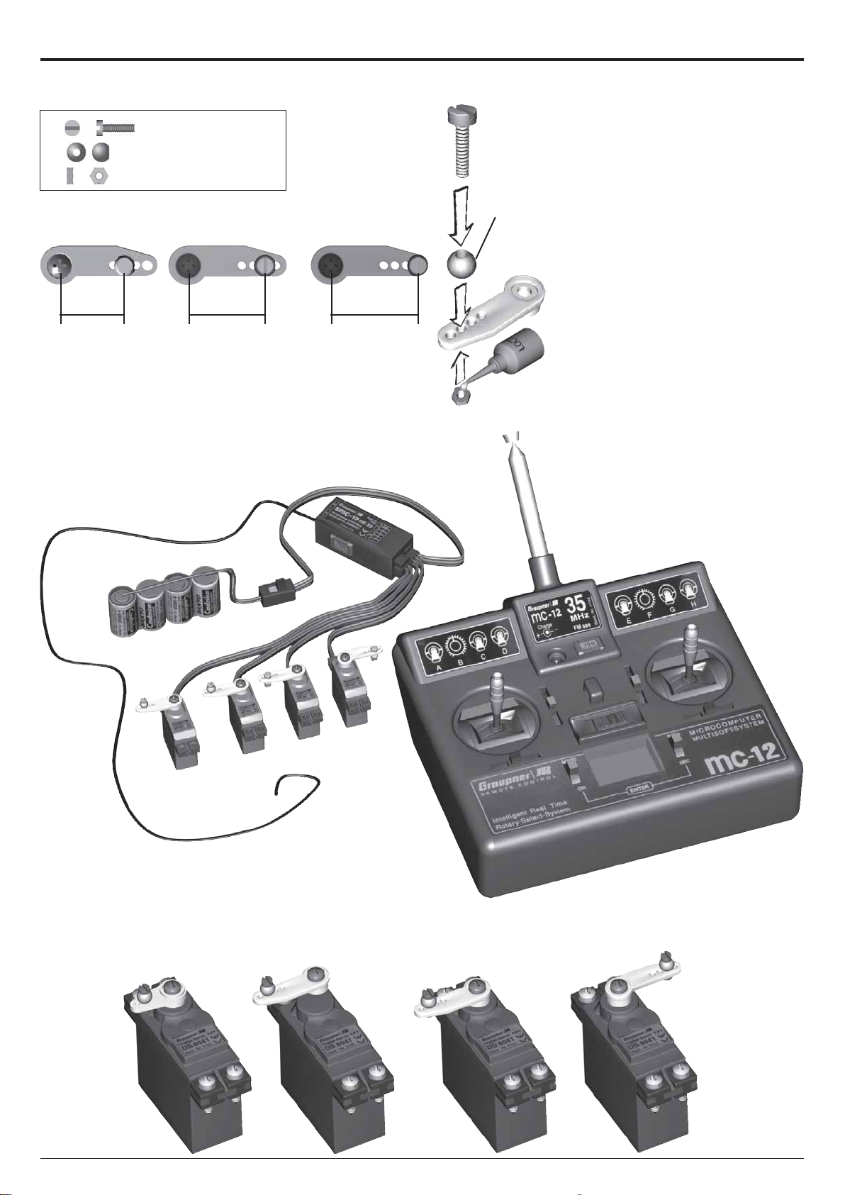
8 Preparation for Servo Installation
4x M2 x8 #1902
4x Ø4,8 mm #1570
4x
Rudder Servo
14-15 mm
.551-.591 in
M2 #2070
Standard Pitch 3D Pitch
18 mm
.709 in
>20 mm
>.787 in
#1570
8.1 Servo Arms
Bag 1 • Bag 12
Now you must decide which pitch
range you wish to use. For different
flying styles, different pitch ranges
must be used. For normal flight with
some aerobatics, choose the standard settings and connect the push
rod at the 18 mm hole on the servo
arm. For 3D flight use 20 mm distance
instead. The ball f or the tail-rotor servo arm should be attached with a distance of 14-15 mm from the servo
arm center.
8.2 Servo Centering
Connect the servo wires to the receiver and set all channels in your
transmitter to neutral. Now attach the
servo arms perpendicular to the servos.
Manual
LOGO 20
Page 19 ©Mikado Modellhubschrauber
Page 20
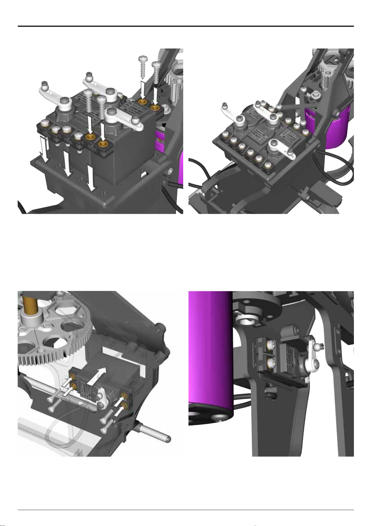
8 Preparation for Servo Installation
8.3 Elevator and Aileron Servos (2x)
8.4 Tail Servo
The use of Futaba servos requires that you take
away a bit of material from the chassis.
Manual
LOGO 20
Page 20 ©Mikado Modellhubschrauber
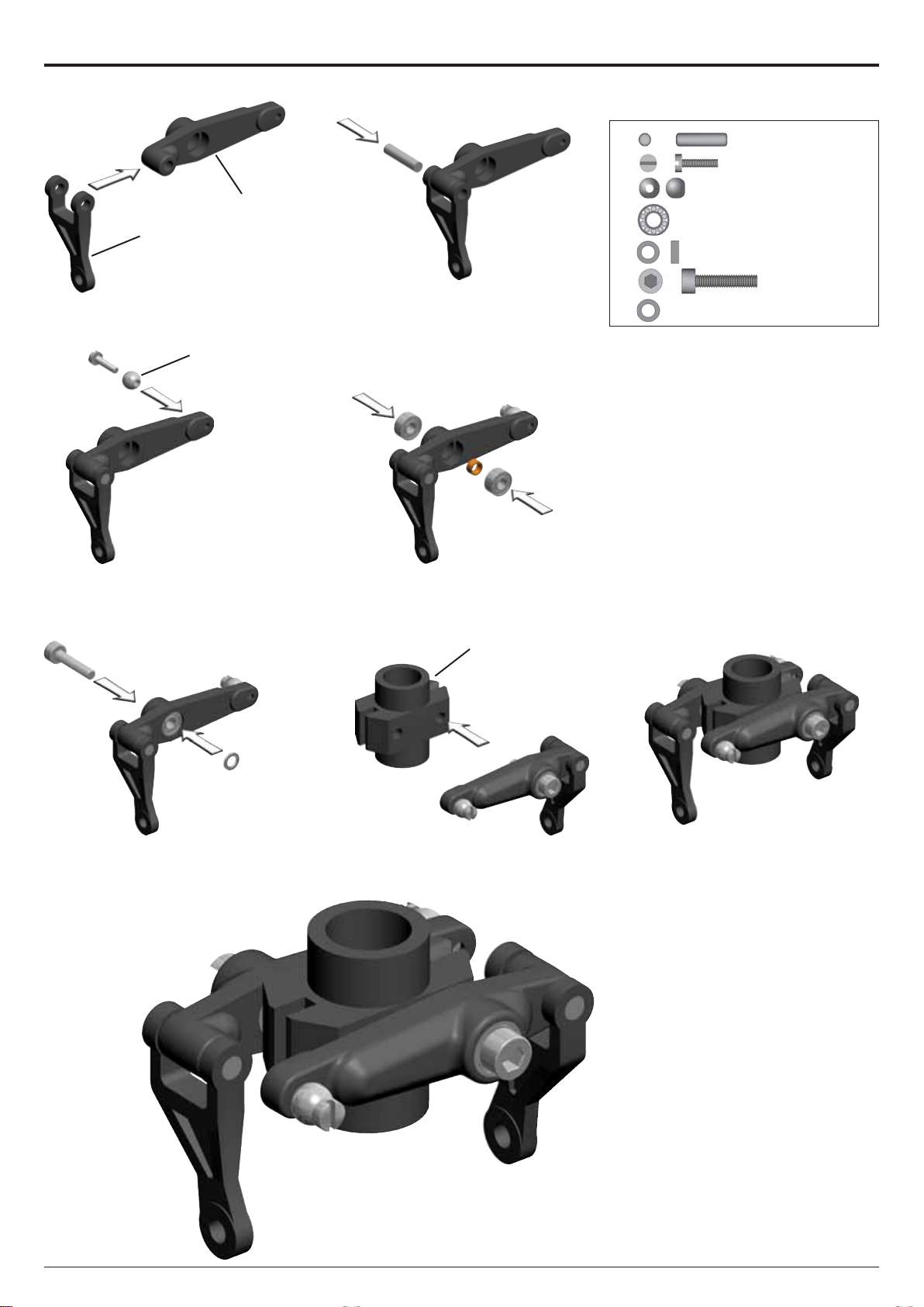
Page 21
#2401
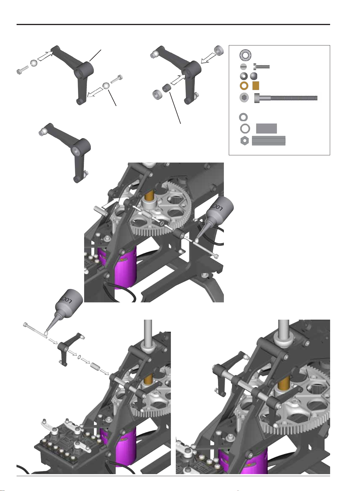
9 Aileron Lever
9 Aileron Lever
Bag 1 • Bag 10 • Bag 12
4x 3x7x3 #930
#1570
#924
4x
4x
2x
2x
2x
2x
1x
Important: The levers f or the left and
right side are different from each
other.
3x5x0,5 #2001
M2x8 #1905
Ø4,8 mm #1570
3x5x4 #924
M3x35 #1961
Ø6x12 #2413
SW5,5x20 #2390
Manual
LOGO 20
Page 21 ©Mikado Modellhubschrauber
Page 22

21 mm
#1588
10 Control Rods
10.1 Length of Control Rods
Bag 1 • Bag 12
84 mm
#1584
56 mm
2x
#1585
3x
10.2 Elevator and Aileron Linkages
Elevator
Elevator
Elevator
Aileron right
Manual
LOGO 20
Page 22 ©Mikado Modellhubschrauber
Page 23

10 Control Rods
10.1 Elevator and Aileron Linkages
Aileron left
Aileron right
Aileron right
Aileron left
Manual
LOGO 20
Aileron right
Elevator
Page 23 ©Mikado Modellhubschrauber
Page 24

11 Swashplate Guide Bracket
Bag 1 • Bag 12
#2383
#2188
#2384
12 Installation of Wash-Out Hub
The wash-out hub must be able to
move up/down easily on the rotor
shaft.
Manual
LOGO 20
Page 24 ©Mikado Modellhubschrauber
Page 25

13 Main Frame without Rotor Head
Manual
LOGO 20
Page 25 ©Mikado Modellhubschrauber
Page 26

14 Tail Rotor
14.1 Tail Rotor Shaft
Bag 5 • Bag 10
#2475
#2466
#2465
1x 2x8mm #2468
2x
2x
Should you have difficulty mounting
the 2x8 mm pin, carefully tap it with a
rubber hammer, or use a vice. The
5x10x4 bearings can likewise be
mounted on the rotor shaft using a
vice and tapping the shaft softly with
a rubber hammer. If the tail rotor shaft
shows axial play after closing the two
halves of the tail rotor case, use one
or two of the 5x10x0.1 washers
which are included in the bag.
5x10x4 #2470
5x10x0.1 #2004
Manual
LOGO 20
#2442
# 2442
#2445
Page 26 ©Mikado Modellhubschrauber
Page 27

14 Tail Rotor
14.2 Vertical Fin
Bag 5 • Bag 12
2x M3x25
#1958
#2490
1x
3x
M3x20 #1957
M3 #2074
Manual
LOGO 20
Page 27 ©Mikado Modellhubschrauber
Page 28

#2455
#2452
14 Tail Rotor
14.3 Pitch Slider
Bag 5 • Bag 10
2x 6x10x2,5 #1440
It is important that the tail pitch plate #2450 is aligned properly on the
control sleeve #2455. In the case of
misalignment, the control sleeve may
be deformed. The mounted tail pitch
plate should be able to move on the
tail rotor shaft with little resistance.
#3030
2x7mm
Manual
LOGO 20
Page 28 ©Mikado Modellhubschrauber
Page 29

14 Tail Rotor
14.4 Tail Rotor Lever
Bag 5 • Bag 10 • Bag 12
2x 3x6x2,5 #2330
#2449
1x
1x
1x
1x
1x
The mounted tail rotor lever should
be able to move with little resistance.
Ø4,8 mm #1570
3x5x5 #2448
3x5x0,5 #2002
M3x14 #1955
M2x8 #1902
Manual
LOGO 20
Page 29 ©Mikado Modellhubschrauber
Page 30

14 Tail Rotor
14.5 Tail Rotor Hub
Bag 5 • Bag 10 • Bag 12
2x M3x12 #1954
2x
3x5x2 #2463
#2458
#2462
4x
1x
3x8x3 #2423
M3x3 #1920
Manual
LOGO 20
Page 30 ©Mikado Modellhubschrauber
Page 31

#2481
#2482
15 Tail
15.1 Tail Boom Assembly
Bag 6 • Bag 11
short
long
Note:There are two different sizes
of tail rotor pushrods: Two are shorter in height than the third.
#2481
The tail boom has two round cutouts on one end. These should be fitted into the matching shapes in the
tail rotor case.
Manual
LOGO 20
Page 31 ©Mikado Modellhubschrauber
Page 32

#2485
15 Tail
15.2 Tail Boom Holder
Bag 6
Manual
LOGO 20
Tur n the tail drive belt 90 degrees
(clockwise).
Page 32 ©Mikado Modellhubschrauber
Page 33

15 Tail
15.3 Tail Drive Pulley
Bag 6 • Bag 10 • Bag 12
1x 4x13x5 #937
1x 4x9x4 #2489
#3001
#2488
2x
1x
1x
1x
4x8x1 #2013
3x5 #1921
M3x18#1965
M3 #2074
Important: Check belt tension
prior to every flight. Incorrect belt
tension can cause disturbances
for your model R/C system.
Incorrect belt tension can lead to
a situation where you lose control
of the tail rotor of your helicopter .
For tightening the belt, pull the tail
boom holder toward the front. Belt
tension is fixed with the M3x18
socket head cap screw for tightening
the tail boom holder to the tail boom.
The belt should be tight. When pressing with your fingers, both sides of
the belt should not come in contact
with each other.
!
Manual
LOGO 20
Page 33 ©Mikado Modellhubschrauber
Page 34

#1560
#2484
15 Tail
15.4 Tail Control Rods
Bag 11 • Bag 12
Screw the two 2 mm ball links onto
the control rods. Their exact positions are of no importance at this point.
The ball ends are attached to the balls
more easily when the text on them is
pointed awa y from the helicopter.
Manual
LOGO 20
Page 34 ©Mikado Modellhubschrauber
Page 35

15 Tail Boom
15.5 Tail Assembly
Bag 6 • Bag 12
4x M3x12 #1954
4x
2x
2x 19 mm #2370
M3x18 #1965
27,5 mm #2370
If you wish to use longer servo arms, it is necessary
that you take away some material from the bottom surface
of the tail boom holder.
Manual
LOGO 20
Page 35 ©Mikado Modellhubschrauber
Page 36

15 Tail
15.6 Tail Rotor Blades
Bag 5 • Bag 12
#2461
Tighten the screws holding the tail
rotor blades, but ensure that the blades move easily in the tail rotor holders under centrifugal force.
2x
2x
M3x14 #1955
M3 #2074
#2491
Manual
#2441
LOGO 20
#2471
15.7 Horizontal Fin
Bag 6 • Bag 12
2x
M3x25 #1958
2x
Avoid overtightening the M3x18
mm socket head cap screws when
drilling them into the plastic frame.
Mount the horizontal stablilizer perpendicular to the vertical fin.
Page 36 ©Mikado Modellhubschrauber
M3 #2074
Page 37

15 Tail
15.8 Tail Boom Brace
Bag 6 • Bag 11 • Bag 12
#2191#2189
2x M3x12 #1954
#1573
#2369
Manual
LOGO 20
Page 37 ©Mikado Modellhubschrauber
Page 38

16 Finished Main Frame & Tail Boom
Manual
LOGO 20
Page 38 ©Mikado Modellhubschrauber
Page 39

#915
2x
17 Main Rotor Head
17.1 Blade Grips
Bag 7 • Bag 10
2x
4x 8x16x5 #954
#3082
17.2 Mixing Arms
Bag 7 • Bag 12
2x
4x
2x
4x
4x
2x
4x
3x7x3 #930
3x5x12 #3090
Ø4,8 mm #1570
M2x8 #1902
M3x35 #1961
M3 Stopp #2074
Manual
LOGO 20
2x
Page 39 ©Mikado Modellhubschrauber
Page 40

#845
17 Main Rotor Head
11.3 Yoke
Bag 7 • Bag 10
4x 8x3 mm #950
2x
8x11 mm #952
Please tighten the M6
capscrew only gently to avoid
unnecessary widening of the
spindle shaft. (If the spindle
shaft widens, it will be difficult
to slide the ball bearings
onto the spindle shaft).
#910
small
inner Ø
2x
2x
2x
2x
11,5x16,8x0,8 mm
#841
8x16 #840
6x12 #2016
M6x12 #1981
#2016
apply grease
#841
large
inner Ø
Manual
LOGO 20
Page 40 ©Mikado Modellhubschrauber
Page 41

17 Main Rotor Head
17.4 Seesaw
Bag 7 • Bag 10 • Bag 12
#935
2x 4x13x5 #937
2x
4x
2x
4x10x4 #726
M2x8 #1902
M2x3 #1900
#939
Manual
LOGO 20
Page 41 ©Mikado Modellhubschrauber
Page 42

#935
17 Main Rotor Head
#3037
17.5 Flybar Control Bridge
Bag 7 • Bag 10
4x M2x10 #1939
4x
M2 #2070
Manual
LOGO 20
Page 42 ©Mikado Modellhubschrauber
Page 43

#965
17 Main Rotor Head
17.6 Flybar
Bag 7 • Bag 11
#856
#3098
2x M3x3 #1920
Manual
LOGO 20
Page 43 ©Mikado Modellhubschrauber
Page 44

17 Main Rotor Head
A
A=B
B
#958
0°
17.7 FlybarPaddles
Bag 7
0°
Manual
LOGO 20
A
Page 44 ©Mikado Modellhubschrauber
A=B
B
Page 45

17 Main Rotor Head
17.8 Final Assembly
Bag 7 • Bag 12
2x
M4x35 #1974
2x
2x
1x M3x18 #1965
1x
M4 #2076
2x30 mm
#912
M3 #2072
Manual
LOGO 20
Page 45 ©Mikado Modellhubschrauber
Page 46

41 mm
#1565
17 Main Rotor Head
17.9 Rotor Head Linkage
Bag 7 • Bag 12
#1569
45 mm
#1586 #1586
Next mount the length-adjusted flybar control linkages. The ball links are
attached to the balls more easily when
the text on them points away from the
helicopter.
Manual
LOGO 20
Page 46 ©Mikado Modellhubschrauber
Page 47

17 Main Rotor Head
2x M2x12 #1942
1x
1x
4,8 #1571
2x4,5x0,5 #2018
Manual
LOGO 20
Page 47 ©Mikado Modellhubschrauber
Page 48

17.10 Logo 10 assembled
Manual
LOGO 20
Page 48 ©Mikado Modellhubschrauber
Page 49

18 RC Installation
Receiver
Receiver Battery
Speed Controller
Manual
LOGO 20
Mounting of 20 cells Mounting of 24 cells
Page 49 ©Mikado Modellhubschrauber
Page 50

18 RC Installation
18.1 Gyro Support Plate
Bag 6 • Bag 12
2x
M3x35 #1961
#2441
#3044
2x
2x
M3 Stopp #2074
3x5x9mm #3043
Manual
LOGO 20
Page 50 ©Mikado Modellhubschrauber
Page 51

19 Decals
Manual
LOGO 20
Page 51 ©Mikado Modellhubschrauber
Page 52

20 How to avoid interference
Please read these guidelines carefully in order to fly safely and without electrical interference.
Flying an electric helicopter means putting several electric components to use. It is essential to avoid that these
components create disturbances for one another . The following guidelines tell you how this is achie ved.
1. Placement of cables
• The wires connecting the motor with the speed controller should be as short as possible. How ever: Do NO T cut
the motor cables (you won’t be able to re-solder the connectors properly). But DO shorten the speed controller
wires.
• Do not place any wires (servo wire, gyro wire, or antenna wire) in the neighborhood of the speed controller or
close to the wires which lead from the speed controller to the motor.
• All wires leading to the receiver should be shortened in such a way that the wires from the servos, gyro and the
on/off switch lead to the receiver f ollowing the shortest distance possible. Any e xcess wire will be a source for
electrical interference.
• The wires connecting the speed controller with the receiver should be placed at as far away from the motor and
from all other electric leads as possible. If you use a Kontronik T ango motor you must use the K ontronik ferrite
ring. This is because this motor is operated at a high frequency . If you use any other motor, the use of the f errite
ring is recommended.
• Never place any wires in the direct neighborhood of the tooth belt or the drive pulley .
2. Gyro
• Comparison of several gyros has shown that the y react differently to the fields generated by the speed controller.
Many piezo gyros, in particular the less expensive ones, are quite likely to pick up disturbances. This may result
in continuous wiggling or sudden turns of tail. At MIKADO we have found that the new Futaba gyros GY240 and
GY401 do not show these problems and that they also work excellent in all other respects.
• Gyros will be sensitive to electric fields when they are placed in the neighborhood of the speed controller, or
when the gyro cables are close to the motor or speed controller. It is therefore recommended that y ou place the
gyro on top of the tail boom holder. You may order a special gyro mounting plate from MIKADO (part no. 2486).
The GY401, and GY240, due to their smaller size, may also be placed within the RC-frame below the servos.
• As with all cables, place gyro cables away from motor and speed controller .
• Note that if your helicopter appears shaky this is not necessarily due to disturbances. Another source could be
that tail pitch slider can’t move freely . Check regularly (ev ery 10 flights).
3. Antenna (very important!)
• The receiver must be placed in the front of the chassis. The antenna leads through the canopy in a line leading
forward (drill small hole through canopy). Get a wire tube and attach it to the landing-bow on one side. Lead the
antenna back through the tube. The front part of the tube will stick out in front of the landing bow at least 10
inches. Of the antenna, when it comes out of the tube, only 2 to 3 inches will stick out. In other words, if any part
of the antenna is hanging lose, it hangs in front of the nose.
• It is best to attach the atenna tube at the lower antenna holders on the landing bow. Such placement of the
antenna will increase the distance between the antenna and other electrical components such as motor, controller
and batteries. In this wa y , reliable perf ormance of the helicopter in all flight positions is ensured.
4. Receiver
• Use up-to-date and first-rate dual conversion receivers. Here at MIKADO we use the Graupner JR receiver
type DS19 (FM/PPM) or SMC19 DS or SMC20 DS (both SPCM).
• On choice of PCM or PPM: In general, we suggest to use PCM receivers. They ha ve optimal range and they
allow for flight without disturbances when all of the abov e guidelines have been f ollowed. If you are uncertain
whether your heli is disturbance-free, it is recommended that you fly PPM first. This allows y ou to diagnose any
potential disturbances.
5. Battery packs
General rule: The more voltage, the more potential for disturbances. Thus, the more cells you fly , the more prev entive
care should be taken against disturbances. Y ou should use inline battery packs (soldered or connected), because
they have both cables in the back (which avoids excess wiring in the front of the helicopter).
Manual
LOGO 20
Page 52 ©Mikado Modellhubschrauber
Page 53

21 RC Programming
120° Swashplate Mixing (120° CCPM)
The LOGO 10 swashplate is designed to be controlled via electronic CCPM. Thus the corect control
inputs of the three swashplate servos are automatically mixed by the R/C transmitter. If you have never
programmed 120° CCPM before, please read this introductory text carefully.
Collective (Pitch)
Pitch function is used to control the lift or sink of the helicopter. When pitch input is given, all three s washplate servos travel together in the same direction and the same amount. As a result the swash-plate
moves up or down on an even level.
We strongly recommend to use a pitch gauge for adjusting the pitch values. If you do not wish to use the
full pitch range (-12° to +12°), you may set the pitch values for minimum and maximum pitch separately
in the R/C transmitter. If you are new to the hobby, we recommend to set minimum pitch at 3°.
Minimum Pitch
Manual
LOGO 20
Page 53 ©Mikado Modellhubschrauber
Page 54

Neutral Pitch (0°)
21 RC Programming
Maximum Pitch
Manual
LOGO 20
Page 54 ©Mikado Modellhubschrauber
Page 55

21 RC Programming
Programming 120° CCPM Programming 120° CCPM
As the programming procedure varies with different types of R/C systems, it is necessary for you to
refer to the instruction manual of your R/C system. Here are only a few general guidelines which apply
to most systems.
Servo Centering with Sub-Trim Function
As indicated in the above sections on mounting the servos, it is important that the servo arms are
exactly centered. You should use the servo sub-trim function of your R/C system for this purpose.
Activating 120° CCPM
Likely, the 120° CCPM function is initially disabled in your R/C transmitter software and needs to be
separately activated. Please refer to your R/C system manual, where you will also find information on
which channels should be used for the elevator servo and the two roll servos. It is important that you
stick with the requirements stated in the manual. Otherwise the 120° CCPM will not function properly.
Your R/C may support various different CCPM mixings. For Logo 20 choose the 120° mixing with two
roll servos in the front and one elevator servo in the back.
Use the relevant menus for setting the mixing proportions for roll, elevator and pitch functions. Begin
by setting the mix values to 50% each. Higher mix values give higher servo travel for that function
This can have the unwanted result that the swashplate reaches its limits and causes damage to the
servos or rods or to the swash-plate itself.
If necessary , you may use the CCPM menu to reverse the direction of the function. This is necessary,
for example, if the swash-plate tilts to the wrong side or the pitch function is inverted. The menu for
reversing servo functions can be used for reversing the movements of individual servo arms, but not
for reversing the entire control function and of all the involved servos.
Aileron and Elevator Travel
The travel range of the aileron and elevator servos are limited by the swashplate’s mechanical limits.
Please take care that the sw ashplate does not hit the maximum of its trav el. This can have the unwanted
result that the swashplte reachies its mechanical limits and causes damage to the servos or rods or to
the swashplate itself. e Gestänge und die Taumelscheibe.
If you desire more agility for your helicopter, use lighter flybar paddles.
Manual
LOGO 20
Page 55 ©Mikado Modellhubschrauber
Page 56

21 RC Programming
Aileron (Roll)
Aileron (roll) is used to control the helicopter’s movements around its longitudinal axis. When aileron
(roll) input is given, the two roll servos (in the front of the swashplate) travel in opposite directions. As a
result the swash-plate tilts to the right or to the left.
Manual
LOGO 20
Page 56 ©Mikado Modellhubschrauber
Page 57

21 RC Programming
Elevator (Tilt)
For tilting the helicopter , use the ele v ator function. F or tilting f orward, the two aileron servos mov e do wnward and the backward elevator servo moves upward. The elevator servo moves twice as much as the
two aileron servos.
Manual
LOGO 20
Page 57 ©Mikado Modellhubschrauber
Page 58

21RC Programming
Aileron and Elevator Travel
The travel range of the aileron and elevator servos are limited by the swash-plate’s mechanical limits.
Please take care that the sw ash-plate does not hit the maximum of its travel. This can ha ve the unwanted
result that the swashplate reaches its mechanical limits and causes damage to the servos or rods to the
swash-plate itself. If you desire more agility for your helicopter, use lighter flybar paddles.
Tail rotor settings
When the servo arm of the tail rotor servo is in the center , the tail rotor lev er and the servo arm should be
perpendicular with respect to each other. The tail rotor pitch lever should never reach its mechanical
limits.
In case the servo travel is too large, you have the following options for correcting this:
1. Move the ball end of the tail rotor servo closer to the center of the servo arm.
2. Reduce the servo travel in your R/C system using ATV.
3. Reduce the servo travel in your gyro (not all gyros have this option).
In case the servo travel is too small, you have the following options for correcting this:
1. Mov e the ball end of the tail rotor servo further awa y from the center of the servo arm.
2. Increase the servo travel in your R/C system using ATV.
3. Increase the servo travel in your gyro (not all gyros have this option).
Ensure that the tail rotor servo turns in the correct direction. If necessary , re v erse the direction of the tail
rotor servo function in your R/C system.
Adjust the tail rotor linkage in
length such that the tail rotor servo
arm and the tail rotor lever are at
90 with respect to each other.
All parts serving the tail rotor
movements must move smoothly.
When there is too much resistance, the tail rotor will not react
to subtle input and the gyro’s
maximum sensitivity cannot be
fully exploited.
Revo-Mix/Gyro
It is necessary to compensate for the torque created by the motor during flight (but not during autorotation).
This compensation is done by adjusting the tail rotor pitch. There are two options for achieving this:
1. Using normal gyro mode
Please refer to your R/C system manual for activating the revolution mixing function and for setting all
parameters correctly. Final settings should be trimmed during test flights.
Manual
LOGO 20
Page 58 ©Mikado Modellhubschrauber
Page 59

RC Programming
2. Using a gyro in Heading-Hold mode
The Heading-Hold gyro mode compensates automatically the deviation caused by the motor torque.
Therefore, if Heading-Hold mode is used, revo-mix should not be programmed additionally.
Important: Check to ensure that the tail rotor assembly mov es smoothly and without play. Otherwise the
gyro and servo will not compensate the torque properly .
Rotor Head RPM control
LOGO 20 is designed to be flown with constant rotor head speed. Irrespective of flight attitude (ascending,
descending, hovering), rotor speed should be kept roughly constant. There are two different methods for
obtaining constant rotor speed:
Rotor speed control with speed controller
All speed controllers can be used in this mode. With speed controller it is necessary to program a throttle
curve (see manual). Programming of throttle curve requires that you associate a given throttle value with
a particular pitch value. In this way, the rotor speed is held almost constant with all pitch values.
Throttle curve programming depends on the type and quality of the R/C system. Simpler , ine xpensiv e R/
C systems designed for model helicopters usually have a 3-point throttle curve. High-end R/C systems
typically have throttle curves with more configurable points (up to 9). Fine tuning of throttle curves will be
necessary during test flights.
Note that an incorrectly programmed throttle curve reduces performance and can lead to overheating of
the motor and the speed controller.
Rotor speed control with governor (RPM regulation mode)
A speed controller with governor function keeps the rotor head speed constant, independent of flight
attitude (ascending, descending, hovering). It is not necessary to program a throttle curve. The head
speed is simply controlled on the radio transmitter using a switch or lever.
Important:
1) Governor mode must be activated in the speed controller first (see manual of the speed controller)
2) In governor mode, the servo wire of the speed controller must not be connected to the throttle channel.
Use a free channel in your radio to connect the servo wire.
Manual
LOGO 20
Page 59 ©Mikado Modellhubschrauber
Page 60

22 Rotor Blades
22.1 Balancing of Rotor Blades
(Center of Gravity)
Place each rotor blade over an
edge as shown in picture (1). Adjust
the blades so that they are in equilibrium. If the center of gravity is not in
the same place in each blade, this
needs to be corrected using tape.
Apply as much tape as necessary
until both blades show their center of
gravity in the same place.
23.2 Static balancing
Screw the rotor blades together as
shown in picture (2). The rotor blades are properly balanced when they
are suspended exactly horizontally.
If one of the rotorblades is not exactly horizontal, the blades are not in
equilibrium.
This is corrected by applying tape
to lighter blade.
When mounting the rotor blades to
the blade holders, note the proper direction (clockwise rotation). Tighten
the cap screws holding the rotor blades, so that the blades cannot move
easily in the blade holders.
Manual
LOGO 20
Page 60 ©Mikado Modellhubschrauber
Page 61

23 Final Pre-Flight Check
23.1 Direction of Main and Tail Rotation
Prior to the first flight double-check
the direction of rotation of the main
rotor head and the tail rotor. For this ,
turn the main gear clock-wise.
23.2 Blade Tracking Adjustment
OKFalse
Prior to the first flight the tracking
of the rotor blades needs to be adjusted. If the tracking is not adjusted
properly, this can cause vibrations
and lead to instability of the helicopter.
Apply colored tape to the tip of one
of the rotor blades. Apply tape of a
different color to the tip of the other
rotor blade. When you are ready for
your first flight, increase the rotor
speed to just before lift-off. From a
safe distance, check the rotor disk
at eye-lev el. V e ry likely , one rotor blade will move below the other.
Make a note of the color of the lowmoving blade. Then turn off the motor and wait until the rotor head has
come to a halt. Lengthen the linkage
(1) of the rotor blade which was moving low by unscrewing the ball links
somewhat. Repeat the checking procedure until both rotor blades move
on the same level.
Manual
LOGO 20
Page 61 ©Mikado Modellhubschrauber
Page 62

2 4 Control Movements
24.1 Pitch/Throttle
You may want to program a different stick mode than the one shown.
Please check which stick mode is
used by other local pilots. Use the
same one, so fellow pilots can assist
you on the field.
Important: Flying a model helicopter requires many hours of training.
During your first attempts, while familiarizing yourself with the different
control movements, keep the helicopter low above the ground (just a
few centimeters/a couple of inches.)
24.2 Rudder
Manual
LOGO 20
Page 62 ©Mikado Modellhubschrauber
Page 63

24 Control Movements
24.3 Elevator
Manual
LOGO 20
24.4 Aileron
Page 63 ©Mikado Modellhubschrauber
Page 64

25 Overview
25.1 Chassis
Manual
LOGO 20
Page 64 ©Mikado Modellhubschrauber
Page 65

25 Overview
25.2 Rotor Head
25.3 Tail Boom/Tail Rotor
Manual
LOGO 20
Page 65 ©Mikado Modellhubschrauber
Page 66

26 Tuning/Accessories
carbon main frame up-grade set
#850
Alu washout unit #973 Carbon tail rotor upgrade
canopy LOGO 24 #852 (must be
used with LOGO 24 main frame #850)
set #3062
carbon servo
holder for tailboom #828
Alu motorplate #3061
light paddles #2357Rotor disk #932 carbon tail boom #832
hollow spindle shaft #846 Carbon rotor blades 600 mm #1050 semi-symmetrical glass-fibre rotor
blades 600mm #1048
Manual
LOGO 20
Page 66 ©Mikado Modellhubschrauber
Page 67

26 Tuning/Accessories
Carbon horizontal fin #2494
carbon elevator lever #2396
carbon vertical fin #2493
alu hex bolts #2372
carbon base plate #2378
Tail boom for 600 mm
rotor blades #2479
Manual
LOGO 20
Page 67 ©Mikado Modellhubschrauber
Page 68

www.Mikado-Heli.de
Construction & Rendering: Mehran Mahinpour Tirooni • Layout & Realisation: CDT-Berlin
 Loading...