

Page 1
www.mikado-heli.de
LOGO 10 3D
© Mikado Modellhubschrauber, V2.0
Mikado Modellhubschrauber • Friedrich-Klausing-Straße 2 • 14469 Potsdam • Germany
Phone +49 (0)331 23749-0 • Fax +49 (0)331 23749-11 • www.mikado-heli.de
Manual
Page 2

Manual
LOGO 10 3D
Page 2 ©Mikado Modellhubschrauber
Index
1 Main Frame .........................................5
1.1 Motorplate 5
1.2 Main Fram e 6
1.3 Bearing Case 7
2 Landing Gear.....................................8
3 Motor Installation ............................... 9
3.1 Motor Adaptor Plate 9
3.2 Motor Attachment 10
4 Main Gear ..........................................11
4.1 Hub 11
4.2 Adjusting Gear Backlash 12
5 Tail Rotor............................................13
5.1 Tail Rotor Shaft 14
5.2 Vertical Fin 14
5.3 Pitch Slider 15
5.4 Tail Rotor Lever 16
5.5 Tail Rotor Hub 17
5.6 Final Assembly 18
6 Tail Boom ...........................................19
6.1 Tail Boom Assembly 19
6.2 Tail Boom Holder 20
6.3 Tail Drive Pulley 21
6.4 Tail Control Rod 22
6.5 Installation 23
6.6 Horizontal Fin 24
6.7 Tail Rotor Blades 24
7 Finished Main Frame & Tail Boom . 2 5
8 Canopy ..............................................26
8.1 Canopy Mounting 26
8.2 Decals 27
9 Swash Plate ...................................... 28
10 Preparation for Servo Installation 2 9
10.1 120° CCPM 29
10.2 Servo Arms 29
10.3 Servo Centering 30
10.4 Linkage 30
11 Servo Installation ........................... 3 1
11.1 Tail Rotor Servo 31
11.2 Elevator Servo 32
11.3 Elevator Linkage/Swashplate 33
11.4 Canopy Fixing Bolts 33
11.5 Aileron Servo left 34
11.6 Aileron Servo right 35
11.7 Aileron Linkage 3 6
12 Wash-Out.........................................37
12.1 Assembly 37
12.2 Installation 38
13 Main Rotor Head ............................ 39
13.2 Head Adjustment 39
13.2 Blade Grips 40
13.3 Mixing Arms 40
13.4 Yoke 41
13.5 Seesaw 42
13.6 Flybar Control Bridge 43
13.7 Ball Bolts 43
13.8 Flybar 44
13.9 Flybar Paddles 44
13.10 Final Assembly 45
13.11 Rotor Head Linkage 46
14 Logo 10 assembled .......................48
15 RC Installation ................................49
15.1 Receiver, Gyro, Speed Controller 49
15.2 Battery 50
16 RC Programming ...........................51
17 Rotor Blades ...................................57
18 Final Pre-Flight Check ..................58
18.1 Direction of Main and Tail Rotation 58
18.2 Blade Tracking Adjustment 58
19 Control Movements.......................59
19.1 Pitch/Throttle 59
19.2 Rudder 59
19.3 Elevator 60
19.4 Aileron 60
20 Overview .........................................61
20.1 Chassis 61
20.2 Rotor Head 62
20.3 Tail Boom/Tail Rotor 63
21 Tuning /Accessories.......................64
All parts shown in the boxes are displayed in real size .
Page 3

Manual
LOGO 10 3D
Page 3 ©Mikado Modellhubschrauber
Safety Instructions
OPERATING YOUR MODEL SAFELY
Operate the helicopter in spacious areas with no people nearby.
! Warning: Do NOT operate the helicopter in the following places and situations
(or else you risk severe accidents):
in places where children gather or people pass through
in residential areas and parks
indoors and in limited space
in windy weather or when there is any rain, snow, fog or other precipitation
If you do not observe these instructions you may be held reliable for personal injury or property damage!
Always check the R/C system prior to operating your helicopter.
When the R/C system batteries get weaker, the operational range of the R/C system decreases. Note that you
may lose control of your model when operating it under such conditions.
Keep in mind that other people around you might also be operating a R/C model.
Never use a frequency which someone else is using at the same time. Radio signals will be mixed and you will
lose control of your model.
If the model shows irregular behavior, bring the model to a halt immediately. Turn off all power switches and
disconnect the batteries. Investigate the reason and fix the problem. Do not operate the model again as long as the
problem is not solved, as this may lead to further trouble and unforeseen accidents.
! Warning: In order to prevent accidents and personal injury, be sure to observe the following:
Before flying the helicopter , ensure that all screws are tightened. A single loose screw may cause a major accident.
Replace all broken or defective parts with new ones, as damaged parts lead to crashes.
Never approach a spinning rotor. Keep at least 10 meters/yards away from a spinning rotor blades.
Do not touch the motor immediately after use. It may be hot enough to cause burns.
Perform all necessar y maintenance.
PRIOR TO ADJUSTING AND OPERATING YOUR MODEL, OBSERVE THE FOLLOWING
! Warning: Operate the helicopter only outdoors and out of people’s reach as the main rotor operates at high rpm!
! Warning: While adjusting, stand at least 10 meters/yards away from the helicopter!
Novice R/C helicopter pilots should always seek advice from experienced pilots to obtain hints with assembly
and for pre-flight adjustments. Note that a badly assembled or insufficiently adjusted helicopter is a safety hazard!
In the beginning, novice R/C helicopter pilots should always be assisted by an experienced pilot and never fly
alone!
Throttle channel should be in motor OFF position while powering up.
When switching the R/C system ON or OFF, always proceed in the following order :
When switching ON:
Position the throttle control stick (on transmitter) to a position where the LOGO 10 motor does not operate.
Turn on the transmitter.
Turn on the receiver.
Connect the motor battery.
Operate your model.
When switching OFF:
Turn off the motor (move throttle control to a position where motor does not operate).
Wait until the rotor head has stopped spinning.
Disconnect the motor battery.
Turn off receiver.
Turn off transmitter.
Page 4
Manual
LOGO 10 3D
Page 4 ©Mikado Modellhubschrauber
Speed-
controller
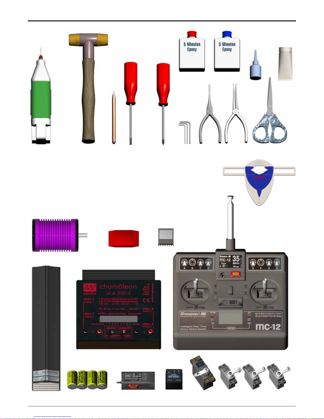
Tools for Assembly & R/C Equipment
Radio with Heli-Software
4x Mini Servos (Graupner DS361
or Graupner C341)
Receiver Battery
(Sanyo AR500)
Battery
Receiver (Graupner DS 19
or SMC 19 SPCM)
Gyro (Futaba GY240
or GY401)
Fast Charger
(Schulze isl 6-330d or isl 6-636+)
Motor + Speed Controller (check the Mikado
webpages for recommended motors)
Alle shown products are examples. You may use different brands.
BEC, replaces
receiver battery
Scissors
Rubber Hammer
Drill with
1.5mm bit
(.059 in)
Marker
Screwdrivers
(plus and minus)
Hex Wrenches
1.5/2.0/2.5/3.0 mm
(.055/.079/.098/.118 in)
Ball
link
pliers
Threadlock
Ball
link
pliers
Grease
Pitch Gauge
Page 5
Manual
LOGO 10 3D
Page 5 ©Mikado Modellhubschrauber
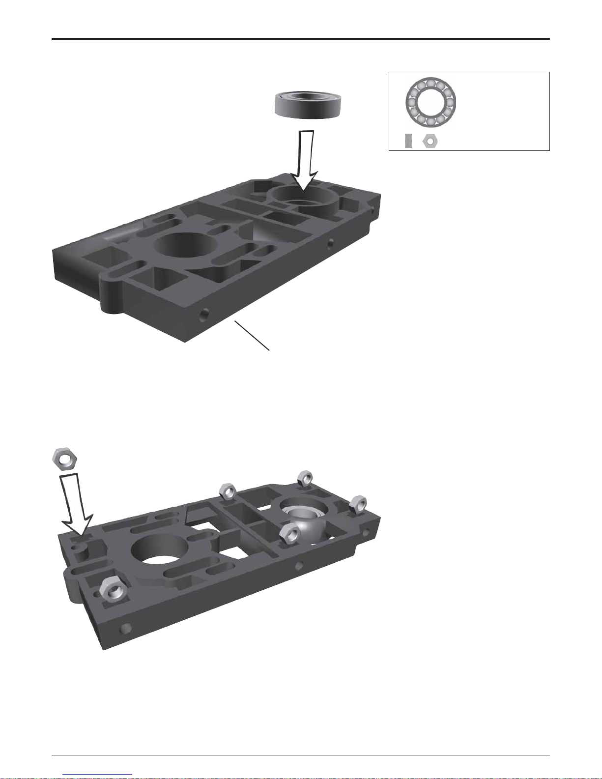
#2379
1x 10x19x5 #1329
6x
M3 #2072
1 Main Frame
1.1 Motorplate
Bag 1 • Bag 10
All parts shown in the
boxes are displayed
in real size.
Page 6
Manual
LOGO 10 3D
Page 6 ©Mikado Modellhubschrauber
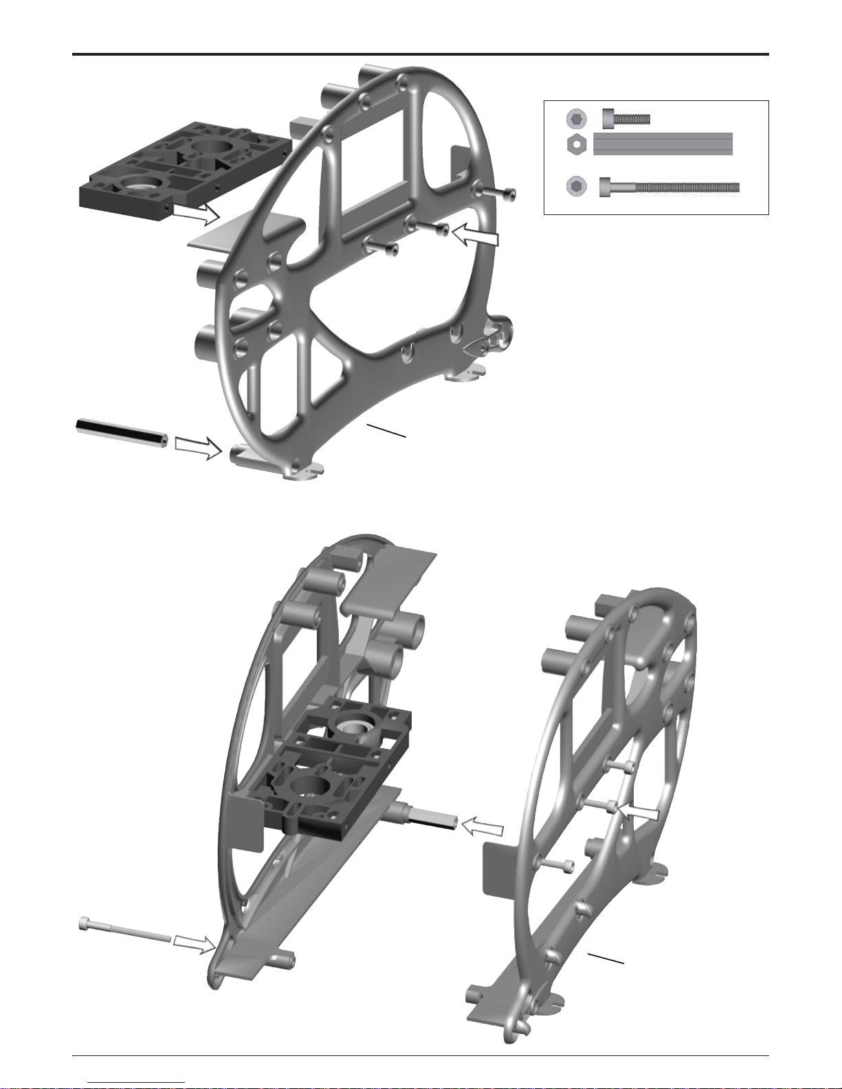
#2720
#2721
6x M3x10 #1953
1x
38 mm #2370
1x
M3x35 #1961
1 Main Frame
1.2 Main Frame
Bag 1
Page 7
Manual
LOGO 10 3D
Page 7 ©Mikado Modellhubschrauber
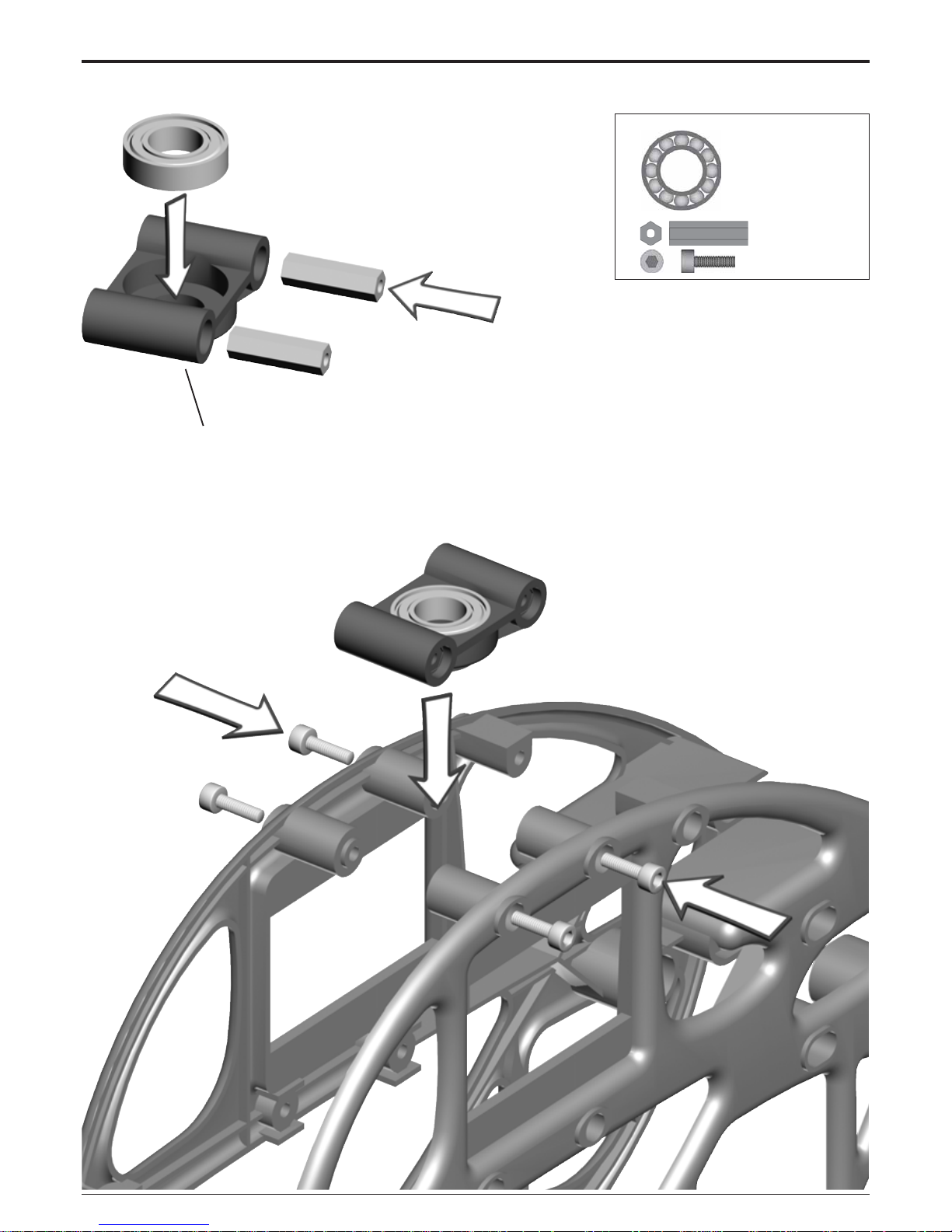
#2380
1x 10x19x5 #1329
2x
19 mm #2370
6x
M3x10 #1953
1 Main Frame
1.3 Bearing Case
Bag 1 • Bag 10
Page 8
Manual
LOGO 10 3D
Page 8 ©Mikado Modellhubschrauber
#2495
#2775
4x M3x12 #1954
4x
M3 #2074
4x
3x7x0,5 #2012
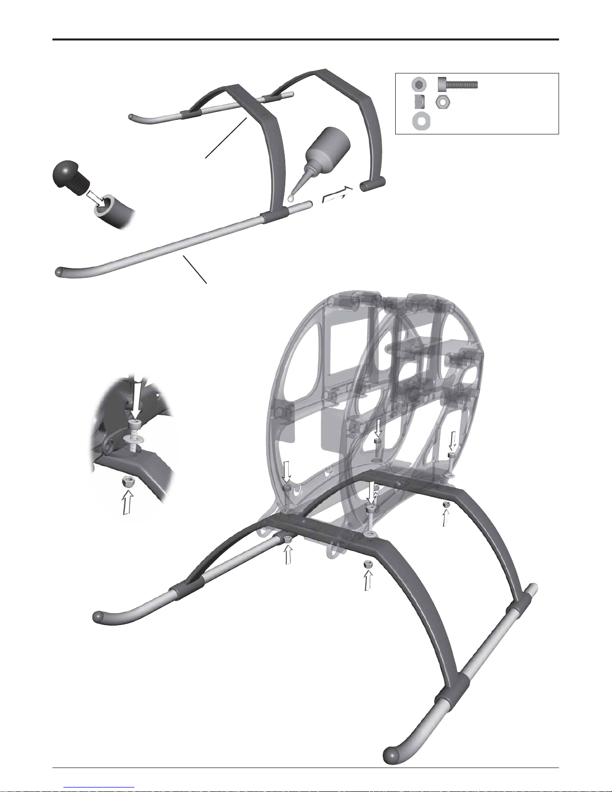
2 Landing Gear
Bag 8
Align the skids and secure them
with superglue.
Page 9
Manual
LOGO 10 3D
Page 9 ©Mikado Modellhubschrauber
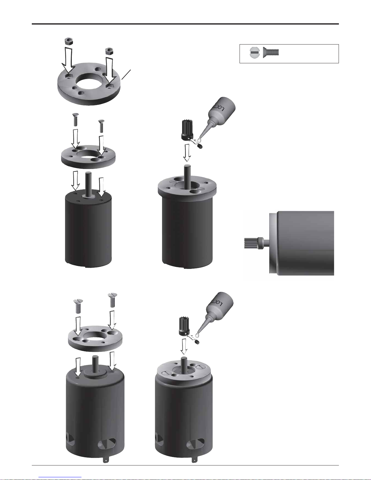
#2499
2x M3x8 #1915
3 Motor Installation
3.1 Motor Adaptor Plate
Bag 1
Some electric motors (e.g. Kontronik, Plettenberg, Speed 700 Neodyme motors) are constructed such
that they cannot be moved along the
motor plate. If you are using one of
these motors, please use the motor
adaptor plate #2499. The plate is not
needed for Hacker motors.
Please check from the Mikado
website which pinion works best with
the motorset you have (on
www.mikado-heli.com go to LOGO
10 and click “Motorization”). When a
wrong pinion is chosen, the performance of your electric helicopter will
deteriorate and the motor or speed
controller can be damaged.
Do not tighten the set screw fully until
the final position of the pinion on the
motor shaft is determined. This is
done after installing the main gear.
There are two options for attaching
the pinion:
1. For securing the pinion, you may
flatten the motor shaft where the set
screw meets the motor shaft - without
making a flat surface on the motor
shaft.
2. Alternatively, you may screw the
set screw directly onto the motor
shaft. For this it is required that the
set screw has an appropriate rim for
engaging the motorshaft (all Mikado
pinions have this rim). Note, howev er,
that after attaching the set screw
once, the rim becomes blunt and may
not be used again.
Page 10
Manual
LOGO 10 3D
Page 10 ©Mikado Modellhubschrauber
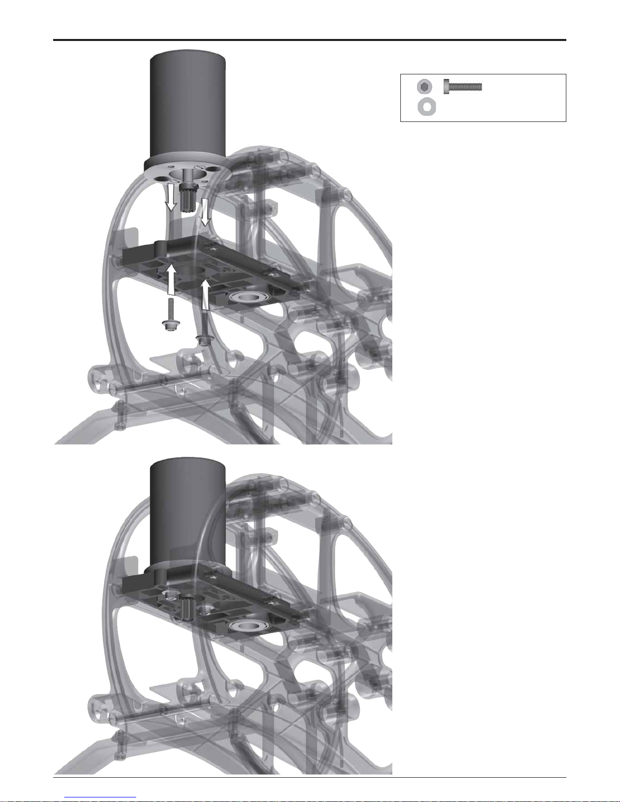
2x M3x12 #1964
2x
3x7x0.5 #2012
3 Motor Installation
3.2 Motor Attachment
Bag 1
When installing the motor, tighten
the socket head cap screws only
slightly, making sure that the motor
can still be moved on the motor plate.
Page 11
Manual
LOGO 10 3D
Page 11 ©Mikado Modellhubschrauber
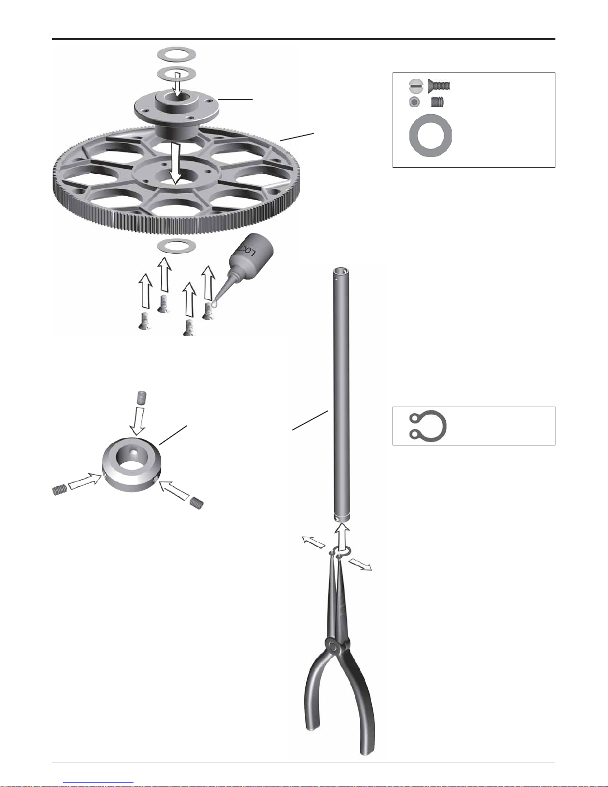
#2731
#2725
#2386
4x M3x8 #1915
3x
M4x5 #1922
2x
10x16x0.5 #2010
1x #1344
#2740
4 Main Gear
4.1 Hub
Bag 2
Do not yet tighten the three M4x5
set screws on the mainshaft collar.
Page 12
Manual
LOGO 10 3D
Page 12 ©Mikado Modellhubschrauber
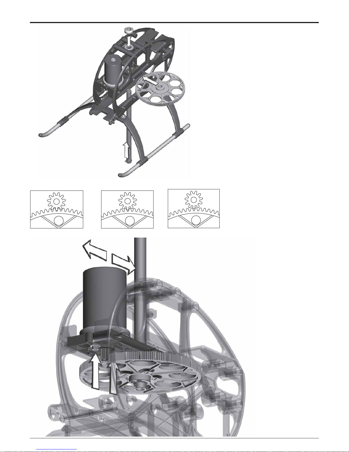
4 Main Gear
Bag 2
After having attached the freeway
hub of the main gear to the rotor shaft,
pull the rotor shaft slightly upward and
simultaneously push the main shaft
collar down onto ball bearing. Next
tighten the set screws. The rotor shaft
should turn easily and it should not
have any axial play.
4.2 Adjusting Gear Backlash
The gear backlash must be adjusted (see drawings). Excess backlash can cause premature wear of the
main gear and will lead to shorter flight
times.
too much backlash correct backlash too little backlash
Page 13
Manual
LOGO 10 3D
Page 13 ©Mikado Modellhubschrauber
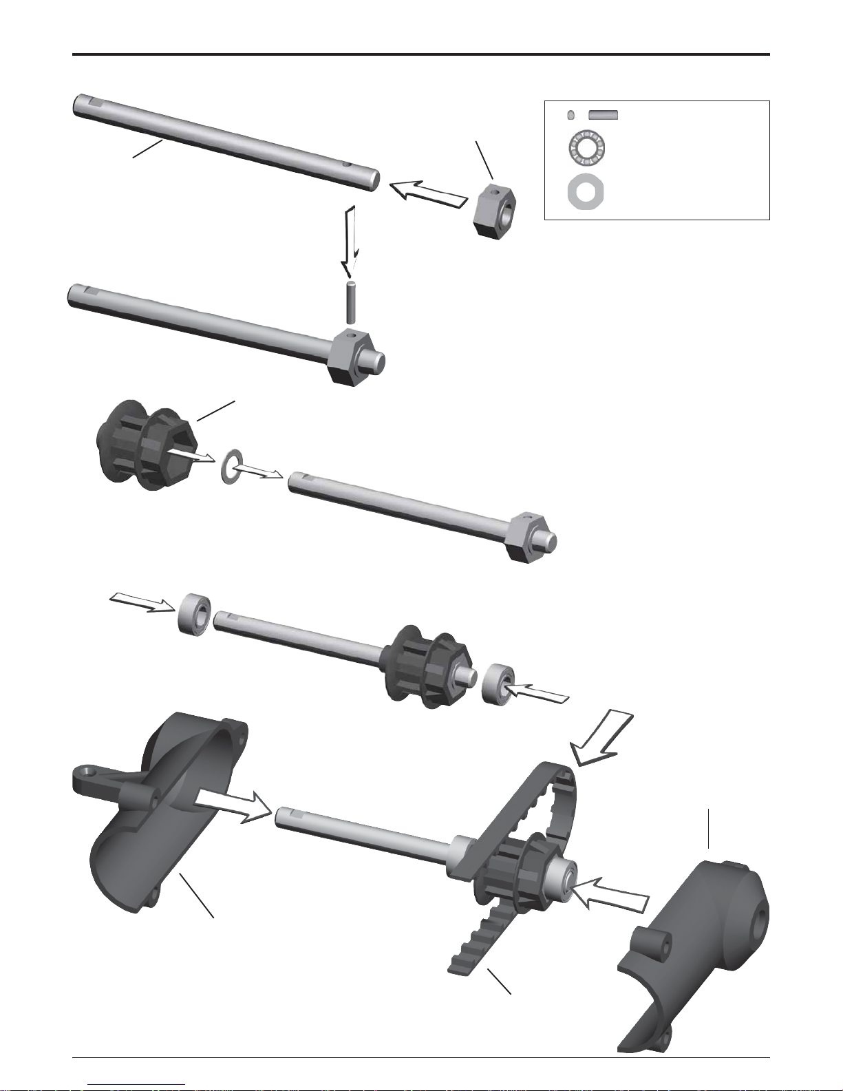
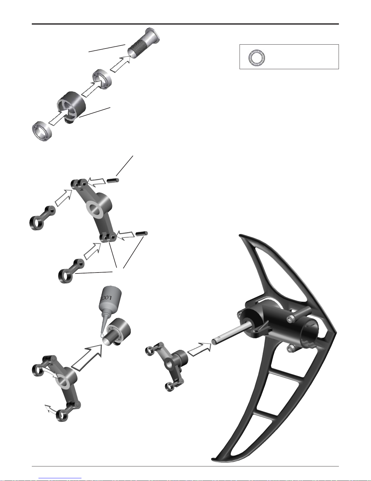
# 2442
#2467
#2476
#2466
#2442
#2765
1x 2x8mm #2468
2x
5x10x4 #2470
2x
5x10x0.1 #2004
5 Tail Rotor
5.1 Tail Rotor Shaft
Bag 5 • Bag 10
Should you have difficulty mounting
the 2x8 mm pin, carefully tap it with a
rubber hammer, or use a vice. The
5x10x4 bearings can also be mounted on the rotor shaft using a vice and
tapping the shaft softly with a rubber
hammer. If the tail rotor shaft shows
axial play after closing the two halves of the tail rotor case, use one or
two of the 5x10x0.1 washers which
are included in the bag.
Page 14
Manual
LOGO 10 3D
Page 14 ©Mikado Modellhubschrauber
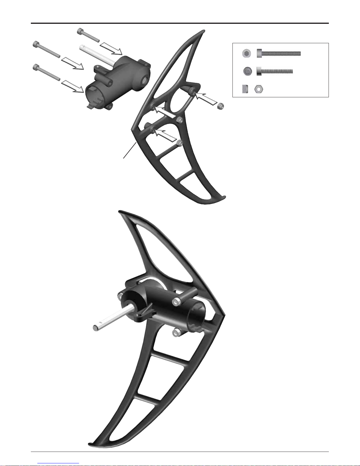
#2490
2x M3x25
#1958
1x
M3x20 #1957
3x
M3 #2074
5 Tail Rotor
5.2 Vertical Fin
Bag 5
Page 15
Manual
LOGO 10 3D
Page 15 ©Mikado Modellhubschrauber
#2455
#2452
2x 6x10x2,5 #1440
#3030
2x7mm
5 Tail Rotor
5.3 Pitch Slider
Bag 5 • Bag 10
It is important that the tail pitch plate #3030 is aligned properly on the
control sleeve #2455. In the case of
misalignment, the control sleeve may
become deformed.
The mounted tail pitch plate should
be able to move on the tail rotor shaft
with little resistance.
Page 16
Manual
LOGO 10 3D
Page 16 ©Mikado Modellhubschrauber
#2449
#2446
2x 3x6x2,5 #2330
1x
M3x14 #1955
1x
M2x8 #1902
1x
#1570
1x
3x5x5 #2448
1x
3x5x0,5 #2002
5 Tail Rotor
5.4 Tail Rotor Lever
Bag 5
The mounted tail rotor lever should
be able to move with little resistance.
Page 17
Manual
LOGO 10 3D
Page 17 ©Mikado Modellhubschrauber
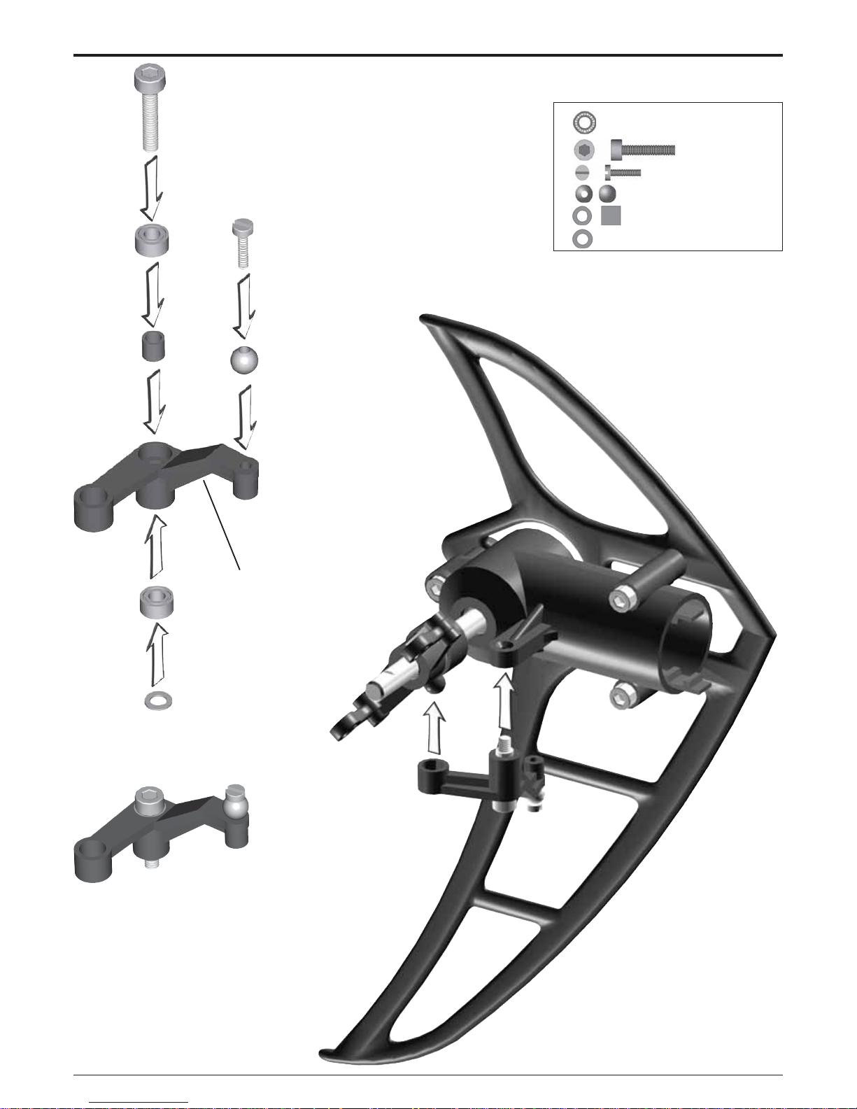
#2462
#2458
2x M3x12 #1954
2x
3x5x2 #2463
4x 3x8x3 #2423
1x
M3x3 #1920
5 Tail Rotor
5.5 Tail Rotor Hub
Bag 5 • Bag 10
Page 18
Manual
LOGO 10 3D
Page 18 ©Mikado Modellhubschrauber
5 Tail Rotor
5.6 Final Assembly
All movable parts of the tail rotor
blade holders should be able to move
with little resistance. When there is
too much resistance, the tail rotor will
not react to subtle input and the gyro’s
maximum sensitivity cannot be fully
exploited.
Page 19
Manual
LOGO 10 3D
Page 19 ©Mikado Modellhubschrauber
#2760
#2763
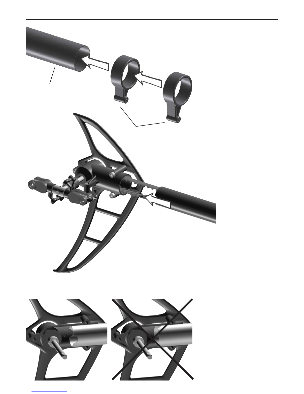
6 Tail Boom
6.1 Tail Boom Assembly
Bag 6 • Bag 11
Note that the two tail rotor pushrod
guides are different in height.
The tail boom has two round cutouts on one end. These should be fitted into the matching shapes in the
tail rotor case.
Page 20
Manual
LOGO 10 3D
Page 20 ©Mikado Modellhubschrauber
#2485
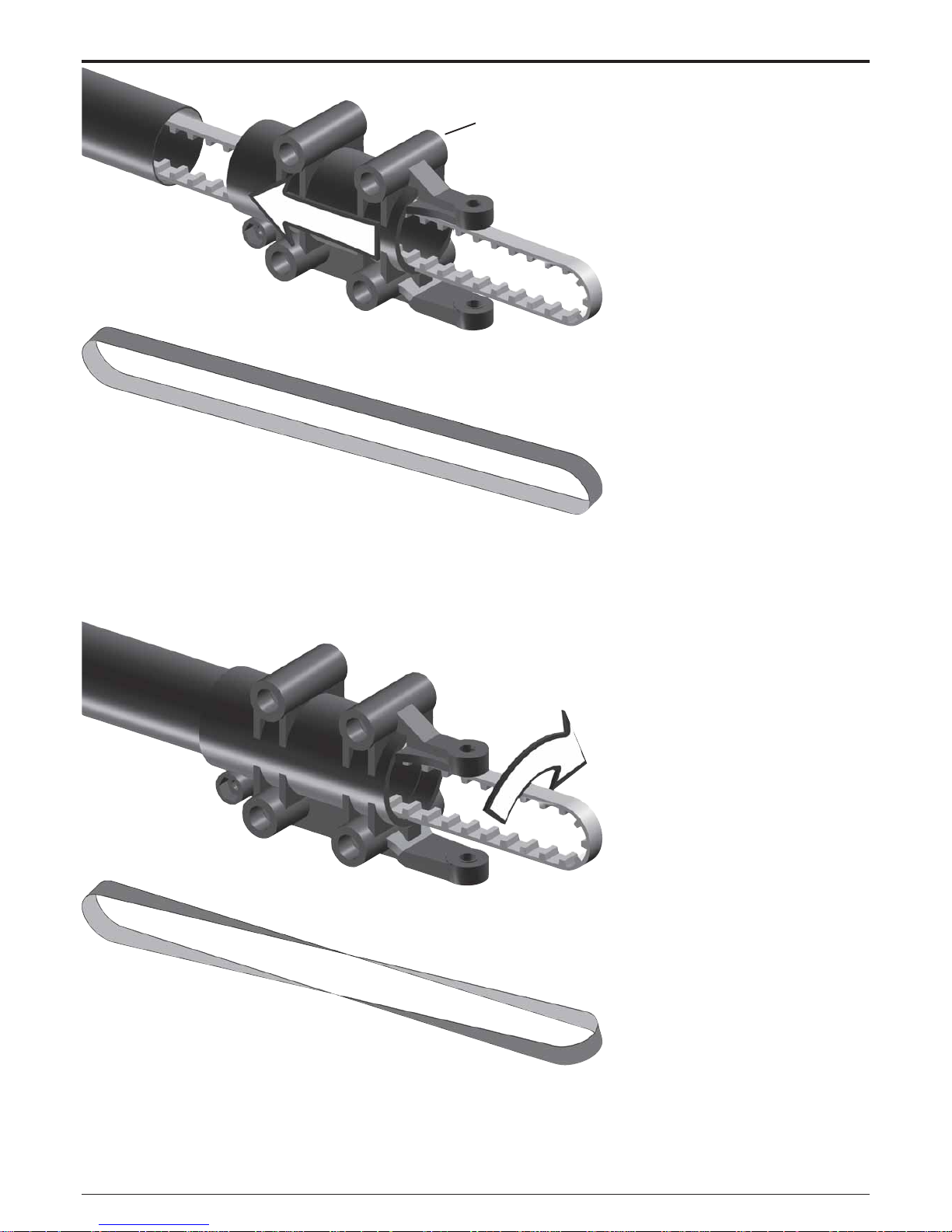
6 Tail Boom
6.2 Tail Boom Holder
Bag 6
Turn the tail drive belt 90° degrees
(clockwise).
Page 21

Manual
LOGO 10 3D
Page 21 ©Mikado Modellhubschrauber
#2728
1x 4x13x5 #937
1x
4x9x4 #2489
2x
4x8x1 #2013
1x
3x5 #1921
1x
M3x18#1965
1x
M3 #2074
#2488
!
6 Tail Boom
6.3 Tail Drive Pulley
Bag 6 • Bag 10
Important: Check belt tension
prior to every flight. Incorrect belt
tension can cause disturbances
for your model R/C system.
Incorrect belt tension can lead to
a situation where you lose control
of the tail rotor of your helicopter.
For tightening the belt pull the tail
boom holder toward the front. Belt
tension is fixed with the M3x18
socket head cap screw for tightening
the tail boom holder to the tail boom.
The belt should be tight. When pressing with your fingers, both sides of
the belt should not come in contact
with each other.
Page 22

Manual
LOGO 10 3D
Page 22 ©Mikado Modellhubschrauber
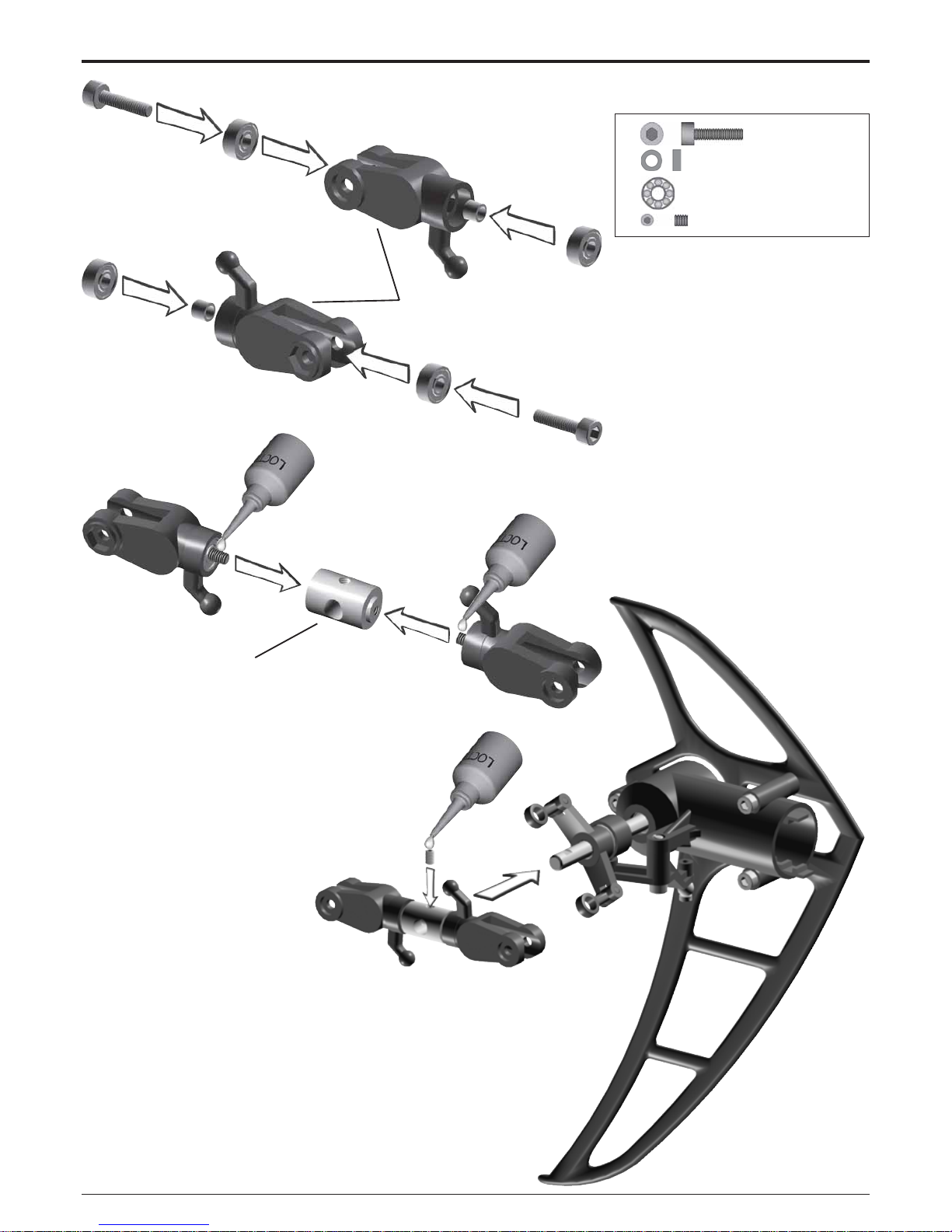
#1560
#2762
6 Tail Boom
6.4 Tail Control Rod
Bag 6
Screw the two 2 mm ball links onto
the control rods. Their exact positions are of no importance at this point.
The ball ends are attached to the balls
more easily when the text on them is
pointed awa y from the helicopter.
Page 23

Manual
LOGO 10 3D
Page 23 ©Mikado Modellhubschrauber
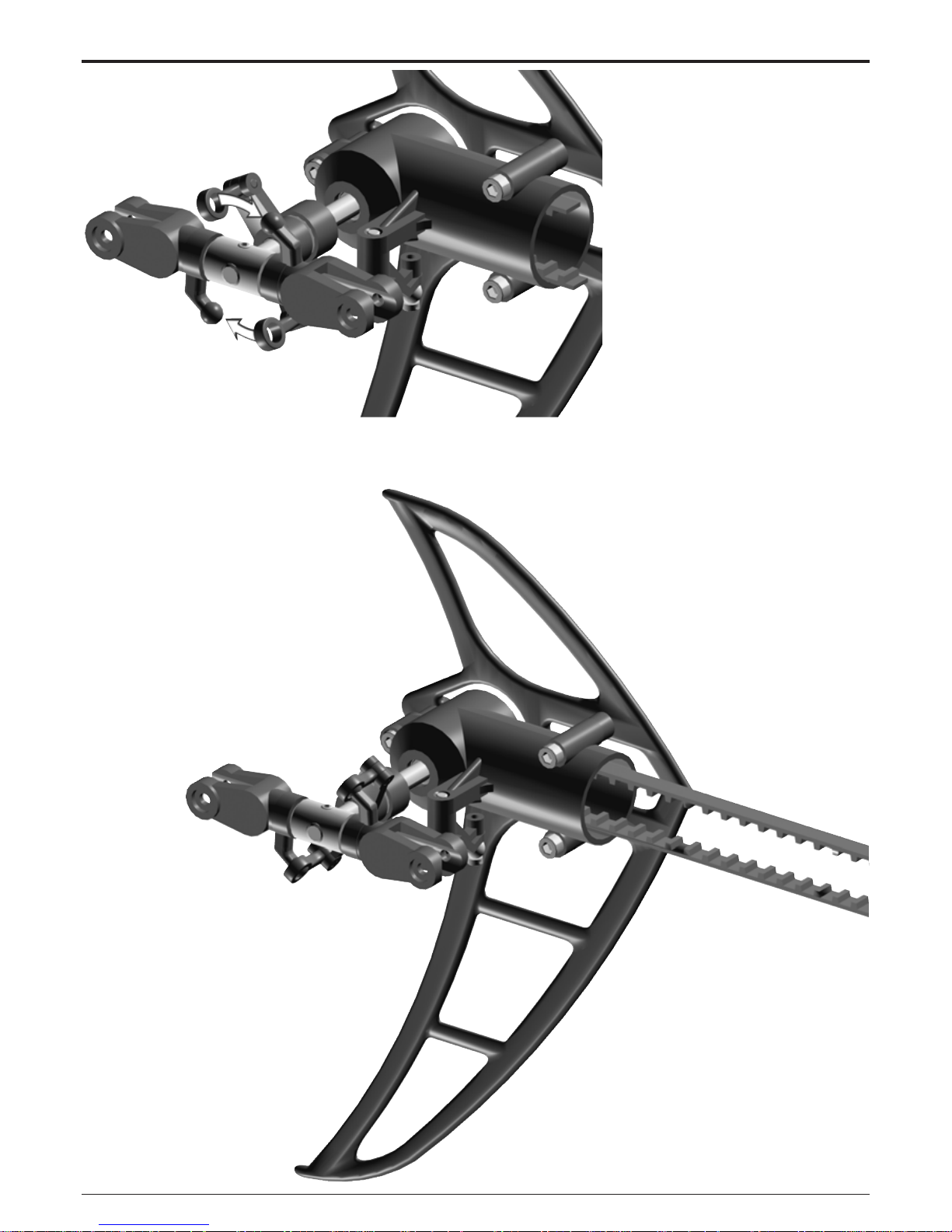
8x M3 x12 #1954
2x
27,5 mm
#2370
2x
23 mm
#2370
2x M3x14 #1955
2x
M3 #2074
6 Tail Boom
6.5 Installation
Bag 6
For mounting the tail assembly in
the side-frames, pull the rear ends of
the side-frames apart.
6.6 Tail Rotor Blades
Bag 5
Tighten the screws holding the tail
rotor blades, but ensure that the blades move easily in the tail rotor holders under centrifugal force.
Page 24

Manual
LOGO 10 3D
Page 24 ©Mikado Modellhubschrauber
2x
M3x30 #1962
2x
M3 #2074
4x
4,8 mm #1574
4x
M2,5x30 #2770
2x
M3x20 #1957
2x
3x5x2 #2463
#721
#1565
#2441
#2491
6 Tail Boom
6.7 Tail Boom Brace
Bag 1 • Bag 6 • Bag 9
5 min epoxy
The ball links should be screwed
onto the control rod such that one is
turned at 90 degrees with respect to
the other.
Page 25

Manual
LOGO 10 3D
Page 25 ©Mikado Modellhubschrauber
7 Finished Main Frame & Tail Boom
Page 26

Manual
LOGO 10 3D
Page 26 ©Mikado Modellhubschrauber
2x 4x11x5mm #2503
#3097
8 Canopy
8.1 Mounting
Bag 1
The canopy does not yet have any
holes for attaching it to the helicopter. In order to fit the canop y properly
to your model, please proceed as follows: First, use rod no. 743 for marking where the holes will be cut out.
Push the rod through the mainframe,
as shown in the picture. Then position the canopy exactly like you want
it to be attached to your helicopter.
The lower end of the canopy will almost touch the tail boom. Close the
canopy with tape, letting the two halves overlap slightly.
Now apply light pressure to the
canopy in the area of the two ends of
the rod. In this way you will obtain
round marks just where you need to
drill the holes for attaching the canopy. Drill two holes with 8mm diameter each. After drilling, place a canopy fixing ring no. 2503 into each hole.
Page 27

Manual
LOGO 10 3D
Page 27 ©Mikado Modellhubschrauber
#3064
8 Canopy
8.2 Decals
8.1 Mounting
Bag 1
For closing the backs of the canopy properly, attach the velcro tape to
the overlapping area.
Page 28

Manual
LOGO 10 3D
Page 28 ©Mikado Modellhubschrauber
#1004
#997
#1005
#2364
9 Swashplate
Swashplate Assembly
Bag 3
Secure all pivot bolts with threadlock.
Important: Tighten the pivot bolts
carefully . Do not overtighten them, as
they will break off.
Page 29

Manual
LOGO 10 3D
Page 29 ©Mikado Modellhubschrauber
120°
1x M2x8 #1902
3x
M2x10 #1903
7x M2 #2070
4x
4,8 #1570
14-15 mm
.551-.591 in
20 mm
.787 in
10 Preparation for Servo Installation
10.1 120° CCPM
The swashplate in the LOGO 10
3D is designed to be operated by
three servos. The transmitter provides for electronic mixing.
10.2 Servo Arms
Bag 1
Rudder Servo Elevator Servo Aileron Servo Aileron Servo
Page 30

Manual
LOGO 10 3D
Page 30 ©Mikado Modellhubschrauber
44 mm (1.732 in)
43 mm (1.693 in)
12 mm
(.472 in)
#1586
#1586
#2770
10 Preparation for Servo Installation
10.3 Servo Centering
Connect the servo wires to the receiver and set all channels in your
transmitter to neutral. Now attach the
servo arms perpendicular to the servos.
120° CCPM
Rudder Servo Elevator Servo Aileron Servo left Aileron Servo right
Linkage measurements for 3D
pitch range (-12° to +12°)
10.4 Linkage
Bag 7 • Bag 9
Important: Remove bridge
Page 31

Manual
LOGO 10 3D
Page 31 ©Mikado Modellhubschrauber
11 Servo Installation
11 .1 Tail Rotor Servo
With LOGO 10 side-frames you
can use two different sizes of tail rotor servos. A larger standard-size tail
rotor servo can be mounted to the left
side-frame, a smaller mini servo is
mounted to right side-frame.
For determining the appropriate
position for mounting the tail rotor
servo, place the servo against the
chassis and mark the holes for attachment with a pen or needle. Then
drill where you have made the markings. The ball links are attached
more easily when the text on them
are pointed away from the helicopter .
Servo mounting at tail boom
(not included in the kit)
Page 32

Manual
LOGO 10 3D
Page 32 ©Mikado Modellhubschrauber
#2364
11 Servo Installation
11.2 Elevator Servo
Bag 3
For determining the best position for
the elevator servo, place the servo
against the chassis and mark the attachment holes with a pen or needle.
Then drill where you have made the
markings.
Swashplate servo installation
When microservos
are used, the linikages
should be aligned as
close as possible to vertical.
When using larger servos the linkages should
be aligned as close as
possible to vertical or
have the same angle.
Incorrect! Incorrect!
Page 33

Manual
LOGO 10 3D
Page 33 ©Mikado Modellhubschrauber
#2383
#2384
#2382
11 Servo Installation
11.3 Elevator Linkage/Swashplate
11.4 Canopy Fixing Bolts
Bag 1
Page 34

Manual
LOGO 10 3D
Page 34 ©Mikado Modellhubschrauber
11 Servo Installation
11.5 Aileron Servo left
Page 35

Manual
LOGO 10 3D
Page 35 ©Mikado Modellhubschrauber
11 Servo Installation
11.6 Aileron Servo right
Page 36

Manual
LOGO 10 3D
Page 36 ©Mikado Modellhubschrauber
11 Servo Installation
11.7 Aileron Linkage
Page 37

Manual
LOGO 10 3D
Page 37 ©Mikado Modellhubschrauber
#979
#981
#972
#1570
2x 2x8mm #980
2x M2x8 #1902
2x
Ø4,8 mm #1570
4x 3x7x3 #930
2x
3x5x2,1 #2463
2x
M3x14 #1955
2x
3x5x0,5 #2002
12 Wash-Out
12.1 Assembly
Bag 3
The Y-rods #981 must be able to
move easily on the wash-out.
Page 38

Manual
LOGO 10 3D
Page 38 ©Mikado Modellhubschrauber
12 Wash-Out Hub
12.2 Installation
The wash-out hub must be able to
move up/down easily on the rotor
shaft.
Page 39

Manual
LOGO 10 3D
Page 39 ©Mikado Modellhubschrauber
2x 3x4x12 #3032
#3032
13 Main Rotor Head Adjustment
13.1 Head Adjustment
3D Performance
Stable Flight Performance
more agility
less agility
more agility
less agility
Before mounting the rotor head, please choose from one of the following
two types of head adjustment, as
they will influence the agility and stability of the helicopter.
1) very agile, very direct cyclic re-
sponse, suitable for 3D-style flying.
2) very stable performance, calm
cyclic response, very suitable for
flying straight, even at low rotor head
speed
Page 40

Manual
LOGO 10 3D
Page 40 ©Mikado Modellhubschrauber
4x 8x14x4 #2351
4x
M2x8 #1902
4x
4,8 #1570
2x
M3x25 #1958
4x
3x7x3 #930
2x
3x5x12 #3090
#2314
2x
#3082
2x
2x
2x
13 Main Rotor Head
13.2 Blade Grips
Bag 7 • Bag 10
13.3 Mixing Arms
Bag 7 • Bag 10
Page 41

Manual
LOGO 10 3D
Page 41 ©Mikado Modellhubschrauber
#2344
4x 3x7 #951
2x
8x11x1 #952
2x 6x14x5 #2349
2x
10x14x0,5 #2351
2x
M4x12 #1972
2x
4x12x1 mm #2015
#910
13 Main Rotor Head
13.4 Yoke
Bag 7
large
inner Ø
apply grease
small
inner Ø
Tuning: #3092 extra hard
dampening, not included
#2756 medium hard dampening,
included in the kit
Page 42

Manual
LOGO 10 3D
Page 42 ©Mikado Modellhubschrauber
#935
2x 4x13x5 #936
2x
4x10x4 #726
2x M2x3 #1900
4x
M2x8 #1902
#940
#935
13 Main Rotor Head
13.5 Seesaw
Bag 7 • Bag 12
Note: The screws are tightened
more easely when some grease
is applied.
Page 43

Manual
LOGO 10 3D
Page 43 ©Mikado Modellhubschrauber
4x M2x10 #1939
4x M2 #2070
#965
#3037
#3039
#3084
13.7 Ball Bolts
Bag 7
13 Main Rotor Head
13.6 Flybar Control Bridge
Bag 7
Page 44

Manual
LOGO 10 3D
Page 44 ©Mikado Modellhubschrauber
4x M3x3 #1920
A
B
A=B
#2359
#2360
13 Main Rotor Head
13.8 Flybar
Bag 7
13.9 Flybar Paddles
Bag 7
Page 45

Manual
LOGO 10 3D
Page 45 ©Mikado Modellhubschrauber
2x
M3x25 #1975
2x M3 #2074
2x
2x30 mm #912
1x
M3x18#1965
1x
M3 #2072
A=B
A
B
0°
0°
13 Main Rotor Head
13.10 Final Assembly
Bag 7 • Bag 12
Page 46

Manual
LOGO 10 3D
Page 46 ©Mikado Modellhubschrauber
13 Main Rotor Head
13.11 Rotor Head Linkage
Next mount the length-adjusted flybar control linkages. The ball links are
attached to the balls more easily when
the text on them is pointed away from
the helicopter.
13.10 Final Assembly
Bag 7
The linkages between the swashplate and the mixing arms are used
later to adjust the rotor blade tracking.
Page 47

Manual
LOGO 10 3D
Page 47 ©Mikado Modellhubschrauber
2x M2x12 #1942
2x
4,8 #1571
2x 2x4,5x0,5 #2018
13 Main Rotor Head
Page 48

Manual
LOGO 10 3D
Page 48 ©Mikado Modellhubschrauber
14 Logo 10 assembled
Page 49

Manual
LOGO 10 3D
Page 49 ©Mikado Modellhubschrauber
#2478
15 RC Installation
15.1 Receiver, Gyro, Speed Controller
Important:
1) Use only high-quality receivers,
preferably the most up-to-date PCM
receivers.
Lower-quality receivers may lead to
disturbances or motor shut-offs.
2) Attach the antenna wire in such a
way that it cannot touch any other
wires or any parts of the helicopter
except for the antenna leads in the
landing bows where the antenna is
meant to be attached.
3) The servo
wire of the speed controller must be
placed in such a way that it is isolated
from any other wires.
4) Do not place any wires in the
neighborhood of the tooth belt.
5) Do not use braces made from metal
or any other metal parts for attaching
the gyro, horizontal stabilizer or tail
boom brace on the tail boom.
6) If you are using a separate BEC,
attach it on the bottom side of the
mainframe and lead the live wire to
the receiver in such a way that it
cannot touch any other wires.
Page 50

Manual
LOGO 10 3D
Page 50 ©Mikado Modellhubschrauber
#2724
15 RC Installation
15.2 Battery
Use cable tie straps to simplify re-
moval of battery fixing rings.
This kit contains battery rings of
four different sizes. Please use those battery rings which will fit the battery used in your heli. The batteries
must be mounted securely!
Page 51

Manual
LOGO 10 3D
Page 51 ©Mikado Modellhubschrauber
16 RC Programming
120° Swashplate Mixing (120° CCPM)
The LOGO 10 swashplate is designed to be controlled via electronic CCPM. Thus the corect control
inputs of the three swashplate servos are automatically mixed by the R/C transmitter. If you have never
programmed 120° CCPM before, please read this introductory text carefully.
Collective (Pitch)
Pitch function is used to control the lift or sink of the helicopter. When pitch input is given, all three s washplate servos travel together in the same direction and the same amount. As a result the swash-plate
moves up or down on an even level.
Aileron (Roll)
Aileron (roll) is used to control the helicopter’s movements around its longitudinal axis. When aileron
(roll) input is given, the two roll servos (in the front of the swashplate) travel in opposite directions. As a
result the swash-plate tilts to the right or to the left.
Roll to the right
Roll to the right (view from rear)
Minimum Pitch Maximum Pitch
Page 52

Manual
LOGO 10 3D
Page 52 ©Mikado Modellhubschrauber
16 RC Programming
Elevator (Tilt)
For tilting the helicopter , use the ele v ator function. F or tilting f orward, the two aileron servos mov e downward and the backward elevator servo moves upward. The elevator servo moves twice as much as the
two aileron servos.
Elevator forward Elevator forward (view from side)
Programming 120° CCPM
As the programming procedure varies with different types of R/C systems, it is necessary for you to refer
to the instruction manual of your R/C system. Here are only a few general guidelines which apply to most
systems.
Servo Centering with Sub-Trim Function
As indicated in the above sections on mounting the servos, it is important that the servo arms are exactly
centered. You should use the servo sub-trim function of your R/C system for this purpose.
Activating 120° CCPM
Likely, the 120° CCPM function is initially disabled in your R/C transmitter software and needs to be
separately activated. Please refer to your R/C system manual, where you will also find information on
which channels should be used for the elev ator servo and the two roll servos. It is important that you stick
with the requirements stated in the manual. Otherwise the 120° CCPM will not function properly.
Your R/C may support various different CCPM mixings. F or Logo 10 choose the 120° mixing with two roll
servos in the front and one elevator servo in the back.
Use the relevant menus for setting the mixing proportions for roll, elevator and pitch functions. Begin by
setting the mix values to 50% each. Higher mix v alues give higher servo tra v el f or that function This can
have the unwanted result that the swashplate reaches its mechanical limits and causes damage to the
servos or rods or to the swashplate.
If necessary , you ma y use the CCPM menu to rev erse the direction of the function. This is necessary, for
example, if the swashplate tilts to the wrong side or the pitch function is inverted.
The menu for reversing servo functions can be used for reversing the movements of individual servo
arms, but not for reversing the entire control function and of all the involved servos.
Page 53

Manual
LOGO 10 3D
Page 53 ©Mikado Modellhubschrauber
16 RC Programming
Servo Travel
It may be the case that all swash-plate servos do not travel the same distance at maximum deflection.
Even small differences between the 3 servos can prevent the swash-plate from being level during
collective pitch inputs and cause the heli to drift.
In order to correct such servo travel differences, you must increase or decrease the servo travel setting
accordingly. Use the menu ATV for adjusting the end points, if necessary. Do not get this menu mix ed up
with Dual/Rate. (Dual/Rate menu allows using multiple servo travel ranges and toggling between them
during flight.)
Example:
If during maximum pitch the elevator servo travel is slightly smaller than travel of the two aileron servos,
then the swash-plate will be tilted backwards, causing the heli also to drift backwards. In this case you
should increase the travel of the elevator servo.
Setting Pitch Values
Please choose from two different pitch settings, depending on your flying style. The two settings are
illustrated below. The standard range is for beginners and for pilots who will do some aerobatic flight
without extended periods of inverted flight.
The final pitch values must be tested during test flying. Once set, the values will work with the rotor
blades you used. In case you change over to a different set of rotor blades, the pitch values will have to
be adjusted to the properties (size, profile etc.) of the new set.
Increase servo travel of
elevator servo on one side
All servos travel the same
distance at maximum deflection
Page 54

Manual
LOGO 10 3D
Page 54 ©Mikado Modellhubschrauber
0°
0°
0°
16 RC Programming
Pitch Values
Maximum PitchMinimum Pitch 0° Pitch
If you are an experienced pilot and plan on flying inverted, select the 3D settings:
For setting the respective pitch v alues, please use a pitch gauge. The values for minimum and maximum
can be specified in the menus of the transmitter.
Application Low Pitch Stick Centered High. Pitch
3D
– 10º bis – 12º 0º 11º to 12º
Application Low Pitch Hovering (Stick Centered) High Pitch
Standard
– 3º 7º to 8º 11º to 12º
The center position of the sticks in your R/C radio corresponds to 0° pitch of the rotor blades. At 0° pitch,
all levers (servo arms, washout lever, mixing arms) should be in horizontal position. At 0° pitch, the
swashplate is in center position, allowing the same travel in upward (positive pitch) and downward
(negative pitch) direction. This setting results in a linear pitch curve, which is ideal for 3D-style flying.
Pilots who wish to fly with less negative pitch should reduce the pitch curve to approx. -3° pitch. Note that
with this latter set-up the sticks are not at center position for hovering.
Page 55

Manual
LOGO 10 3D
Page 55 ©Mikado Modellhubschrauber
16 RC Programming
Aileron and Elevator Travel
The travel range of the aileron and elevator servos are limited by the swash-plate’s mechanical limits.
Please take care that the swash-plate does not hit the maximum of its tra vel. This can hav e the unwanted
result that the swashplate reaches its mechanical limits and causes damage to the servos or rods to the
swash-plate itself.
If you desire more agility for your helicopter, use lighter flybar paddles.
Tail rotor settings
When the servo arm of the tail rotor servo is in the center, the tail rotor le ver and the servo arm should be
perpendicular with respect to each other. The tail rotor pitch lever should never reach its mechanical
limits.
In case the servo travel is too large, you have the following options for correcting this:
1. Move the ball end of the tail rotor servo closer to the center of the servo arm.
2. Reduce the servo travel in your R/C system using ATV.
3. Reduce the servo travel in your gyro (not all gyros have this option).
In case the servo travel is too small, you have the following options for correcting this:
1. Mo v e the ball end of the tail rotor servo further awa y from the center of the servo arm.
2. Increase the servo travel in your R/C system using ATV.
3. Increase the servo travel in your gyro (not all gyros have this option).
Ensure that the tail rotor servo turns in the correct direction. If necessary , re v erse the direction of the tail
rotor servo function in your R/C system.
Revo-Mix/Gyro
It is necessary to compensate for the torque created by the motor during flight (but not during autorotation).
This compensation is done by adjusting the tail rotor pitch. There are two options for achieving this:
1. Using normal gyro mode
Please refer to your R/C system manual for activating the revolution mixing function and for setting all
parameters correctly. Final settings should be trimmed during test flights.
Adjust the tail rotor linkage in
length such that the tail rotor servo
arm and the tail rotor lever are at
90 with respect to each other.
All parts serving the tail rotor
movements must move smoothly .
When there is too much resistance, the tail rotor will not react
to subtle input and the gyro’s
maximum sensitivity cannot be
fully exploited.
Page 56

Manual
LOGO 10 3D
Page 56 ©Mikado Modellhubschrauber
16 RC Programming
2. Using a gyro in Heading-Hold mode
The Heading-Hold gyro mode compensates automatically the deviation caused by the motor torque.
Therefore, if Heading-Hold mode is used, revo-mix should not be programmed additionally.
Important: Check to ensure that the tail rotor assembly mov es smoothly and without play . Otherwise the
gyro and servo will not compensate the torque properly .
Rotor Head RPM control
LOGO 10 is designed to be flown with constant rotor head speed. Irrespective of flight attitude (ascending,
descending, hovering), rotor speed should be kept roughly constant. There are two different methods for
obtaining constant rotor speed:
Rotor speed control with speed controller
All speed controllers can be used in this mode. With speed controller it is necessary to program a throttle
curve (see manual). Programming of throttle curve requires that you associate a given throttle value with
a particular pitch value. In this way, the rotor speed is held almost constant with all pitch values.
Throttle curve programming depends on the type and quality of the R/C system. Simpler , ine xpensive R/
C systems designed for model helicopters usually have a 3-point throttle curve. High-end R/C systems
typically have throttle curves with more configurable points (up to 9). Fine tuning of throttle curves will be
necessary during test flights.
Note that an incorrectly programmed throttle curve reduces performance and can lead to overheating of
the motor and the speed controller.
Rotor speed control with governor (RPM regulation mode)
A speed controller with governor function keeps the rotor head speed constant, independent of flight
attitude (ascending, descending, hovering). It is not necessar y to program a throttle curve. The head
speed is simply controlled on the radio transmitter using a switch or lever.
Important:
1) Governor mode must be activated in the speed controller first (see manual of the speed controller)
2) In governor mode, the servo wire of the speed controller must not be connected to the throttle channel.
Use a free channel in your radio to connect the servo wire.
Page 57

Manual
LOGO 10 3D
Page 57 ©Mikado Modellhubschrauber
17 Rotor Blades
Carbon Rotor Blades
Rotor blades made from glass-fiber-enhanced plastic or carbon are
typically in ready-to-fly condition
when new. It will only be necessary
to adjust blade tracking.
Wooden Rotor Blades
Balancing of Rotor Blades (Center of Gravity)
Place each rotor blade over an
edge as shown in picture (1). Adjust
the blades so that they are in equilibrium. If the center of gravity is not in
the same place in each blade, this
needs to be corrected using tape.
Apply as much tape as necessary
until both blades show their center of
gravity in the same place.
Static balancing
Screw the rotor blades together as
shown in picture (2). The rotor blades are properly balanced when they
are suspended exactly horizontally.
If one of the rotorblades is not exactly horizontal, the blades are not in
equilibrium.
This is corrected by applying tape
to lighter blade.
When mounting the rotor blades to
the blade holders, note the proper direction (clockwise rotation). Tighten
the cap screws holding the rotor blades, so that the blades cannot move
easily in the blade holders.
Page 58

Manual
LOGO 10 3D
Page 58 ©Mikado Modellhubschrauber
18 Final Pre-Flight Check
18.1 Direction of Main and Tail Rotation
Prior to the first flight the tracking
of the rotor blades needs to be adjusted. If the tracking is not adjusted
properly, this can cause vibrations
and lead to instability of the helicopter.
Apply colored tape to the tip of one
of the rotor blades. Apply tape of a
different color to the tip of the other
rotor blade. When you are ready for
your first flight, increase the rotor
speed to just before lift-off. From a
safe distance, check the rotor disk
at eye-lev el. V ery likely, one rotor blade will move below the other.
Make a note of the color of the lowmoving blade. Then turn off the motor and wait until the rotor head has
come to a halt. Lengthen the linkage
(1) of the rotor blade which was moving low by unscrewing the ball links
somewhat. Repeat the checking procedure until both rotor blades move
on the same level.
Prior to the first flight double-check
the direction of rotation of the main
rotor head and the tail rotor.
18.2 Blade Tracking Adjustment
OKFalse
Page 59

Manual
LOGO 10 3D
Page 59 ©Mikado Modellhubschrauber
19 Control Movements
19.1 Pitch/Throttle
19.2 Rudder
You may want to program a different stick mode than the one shown.
Please check which stick mode is
used by other local pilots. Use the
same one, so fellow pilots can assist
you on the field.
Important: Flying a model helicopter requires many hours of training.
During your first attempts, while familiarizing yourself with the different
control movements, keep the helicopter low above the ground (just a
few centimeters/a couple of inches.)
Page 60

Manual
LOGO 10 3D
Page 60 ©Mikado Modellhubschrauber
19 Control Movements
19.3 Elevator
19.4 Aileron
Page 61

Manual
LOGO 10 3D
Page 61 ©Mikado Modellhubschrauber
2366
969
972
981
930
979
978
982
981
2365
1565
2770
2386
1329
2380
2370
1922
2721
2189
2725
1915
2730
1329
2379
2370
2731
2072
1954
1961
1953
2062
2382
2383
2062
2720
2740
2384
2499
1915
1914
1902
1570
1916
2016
2382
20 Overview
20.1 Chassis
Page 62

Manual
LOGO 10 3D
Page 62 ©Mikado Modellhubschrauber
20 Overview
20.2 Rotor Head
Page 63

Manual
LOGO 10 3D
Page 63 ©Mikado Modellhubschrauber
20 Overview
20.3 Tail Boom/Tail Rotor
Page 64

Manual
LOGO 10 3D
Page 64 ©Mikado Modellhubschrauber
21 Tuning/Accessories
Alu canopy holders #3038 Carbon tail boom #2758 Carbon main rotor blades #2712
Main rotorshaft hardened #2741 Tail rotorshaft hardened #2475 Carbon vertical fin #2780
Carbon horizontal fin #2781 Battery support plate #2782 Clamp ring #2385
Extra hard dampening #3092 Alu hex bolts #2371 Alu washout unit #973
Page 65

Manual
LOGO 10 3D
Page 65 ©Mikado Modellhubschrauber
Gyro plate for chassis #3096 Carbon gyro plate #2486 Alu motorplate #3061
Tail rotor hub with
thrustbearings #3052
Rotor disk #932 Tail boom long (upgrade set) #2769
BEC #2530 Heavy stabilizer paddles #2358 Carbon Tail servo holder #828
Carbon rotor blades #2713
Carbon tail rotor upgrade
set #3062
21 Tuning/Accessories
Page 66

Construction & Rendering: Mehran Mahinpour Tirooni • Layout & Realisation: CDT-Berlin
www.mikado-heli.de
 Loading...