

MII 53248 Datasheet

PRELIMINARY DATA SHEET
53248
Features:
Isolated Controls
•
Isolated Status Outputs
•
Fault Protection
•
28 VDC SOLID STATE POWER CONTROLLER
Thermal Shutdown
Undervoltage & Overvoltage Shutdown
Current Limitation
Short Circuit Protection
DESCRIPTION
HYBRID MICROELECTRONICS
Applications:
Power Distribution In Land/Air/Launch Vehicles
•
Motor Switch
•
Displays/Lamps/Controls
•
Industrial Automation
•
Switching Heaters
•
Test Equipment
•
Machine Control Equipment
•
•
Medical Lab Equipment
Mii
PRODUCTS DIVISION
The 53248 is a 28 VDC Solid State High Side Power Controller (SSPC) that is designed to replace electromagnetic
circuit breakers rated at 10 amperes. It is a high side switch utilizing N-channel vertical power FET technology with
integral charge pump. The SSPC provides a status output that signals a variety of conditions including over
temperature shutdown, overvoltage or undervoltage, over-current or short circuit. It will trip off for any of the above
conditions and automatically (based on an internal thermal time constant) cycle On/Off until the fault or the control
signal is removed.
Using vertical MOSFET technology, the SSPC offers extremely low “ON” resistance. This results in very low power
dissipation, which allows operation over the temperature range of –40°C to +85°C with minimal heat sinking.
ABSOLUTE MAXIMUM RATINGS
= 25°C unless otherwise specified)
(@ T
C
Input Control Current...................................................................................................................................................... 10 mA
Reverse Input Voltage (Control to Signal Ground)..................................................................................................... - 5 VDC
Pins to Case Isolation.............................................................................................................................................. 1000 VDC
Input-Output Isolation .............................................................................................................................................. 1000 VDC
Lead Temperature........................................................................................................................................................ +300°C
Junction Temperature ..................................................................................................................................................+150°C
Micropac Industries cannot assume any responsibility for any circuits shown or represent that they are free from patent infringement.
Micropac reserves the right to make changes at any time in order to improve design and to supply the best product possible.
MICROPAC INDUSTRIES, INC. HYBRID MICROELECTRONICS PRODUCTS DIVISION • 905 E. Walnut St., Garland, TX 75040 • (972) 272-3571 • Fax (972) 494-2281
www.micropac.com E-MAIL: hybridsales@micropac.com
05/16/01
PRELIMINARY DATA SHEET
53248
28 VDC SOLID STATE HIGH SIDE SELF-PROTECTED POWER CONTROLLER
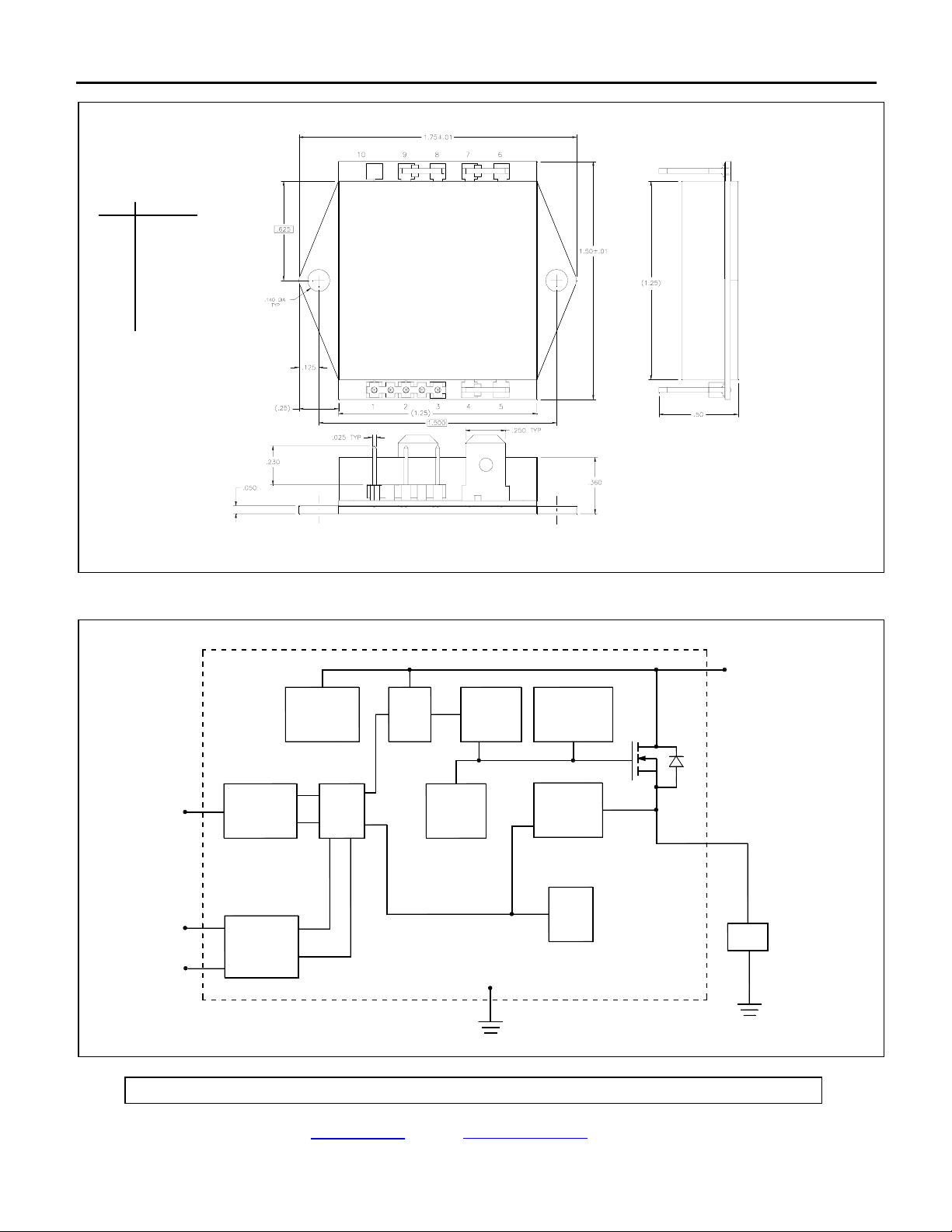
Package Configuration
PIN # FUNCTION
1
CONTROL
STATUS
2
SIGNAL GND
3
OUTPUT
4
5
OUTPUT
POWER IN
6
POWER IN
7
8
POWER GND
POWER GND
9
NC
10
Dimensions: inches
Functional Block Diagram
CONTROL
STATUS
SIGNAL GND
ISOLATION/
CONTROL
ISOLATION/
STATUS
VOLTAGE
REGULATOR
LOGIC
O/V
U/V
CURRENT
LIMIT
CHARGE
PUMP
GATE
PROTECTION
OUTPUT
DETECTION
TEMP
SENSE
(POWER GND)
POWER
IN
OUTPUT
LOAD
Micropac Industries cannot assume any responsibility for any circuits shown or represent that they are free from patent infringement.
Micropac reserves the right to make changes at any time in order to improve design and to supply the best product possible.
MICROPAC INDUSTRIES, INC. HYBRID MICROELECTRONICS PRODUCTS DIVISION • 905 E. Walnut St., Garland, TX 75040 • (972) 272-3571 • Fax (972) 494-2281
www.micropac.com E-MAIL: hybridsales@micropac.com
05/16/01

PRELIMINARY DATA SHEET
53248
28 VDC SOLID STATE HIGH SIDE SELF-PROTECTED POWER CONTROLLER
SPECIFICATIONS
25°C unless otherwise specified)
(@ T
C
Control Function
Input Type......................................................................................................... 1.5 kΩ resistor in series with 1.3 V drop LED
Turn-on Control Current ..........................................................................................................................................2 mA (min)
Turn-off Control Current ....................................................................................................................................... 10 µA (max)
Status Function
Open Collector transistor, V
Output High is V
, Output Low is +0.4 V (max) @ ICC = 10 mA (max)
CC
Status output transistor off (logic high) indicates unit is off.
Status output transistor on (V ≤ 0.4 VDC) indicates unit is on.
Power Circuit
Supply Voltage (for normal operation) ................................................................. 5 VDC (min), 28 VDC(typ), 33 VDC (max)
Continuous Current ........................................................................................................................................................... 10 A
On-state Resistance, T
On-state Resistance, T
Minimum Output Voltage Drop (I
Power Dissipation at T
C
Power Output Leakage Through Load ...........................................................................................................................15 µA
Trip Reset Time ................................................................................................................................ Temperature Dependent
Body Diode Current Capacity .......................................................................................................................................... 10 A
Quiescent Current (@ No load) ...................................................................................................................................... 8 mA
= +40 VDC (max)
CC
@ 25°C (IL ≥ 5A) .....................................................................................................................35 m
j
@ 150°C (I
j
5A)....................................................................................................................70 m
≥
L
= 0.5A) ..................................................................................................................... 50 mV
L
= 25°C and Full Load.................................................................................................................. 4 W
Ω
Ω
Temperature Range
Operating (Case) ..............................................................................................................................................-40°C to +85°C
Storage .......................................................................................................................................................... -55°C to +150°C
Thermal Resistance
Junction to Case.........................................................................................................................................................2.5 °C/W
Case to Ambient ...................................................................................................................................................... TBD °C/W
Physical Characteristics
See Package Configuration
Timing at 28 VDC (I
=1A)
L
Turn-on Time ................................................................................................................................................... 200 µsec (max)
Status Turn-on Delay ......................................................................................................................................200 µsec (max)
Turn-off Time ................................................................................................................................................... 250 µsec (max)
Status Turn-off Delay ......................................................................................................................................300 µsec (max)
Micropac Industries cannot assume any responsibility for any circuits shown or represent that they are free from patent infringement.
Micropac reserves the right to make changes at any time in order to improve design and to supply the best product possible.
MICROPAC INDUSTRIES, INC. HYBRID MICROELECTRONICS PRODUCTS DIVISION • 905 E. Walnut St., Garland, TX 75040 • (972) 272-3571 • Fax (972) 494-2281
www.micropac.com E-MAIL: hybridsales@micropac.com
05/16/01
 Loading...